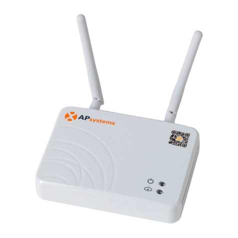
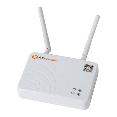
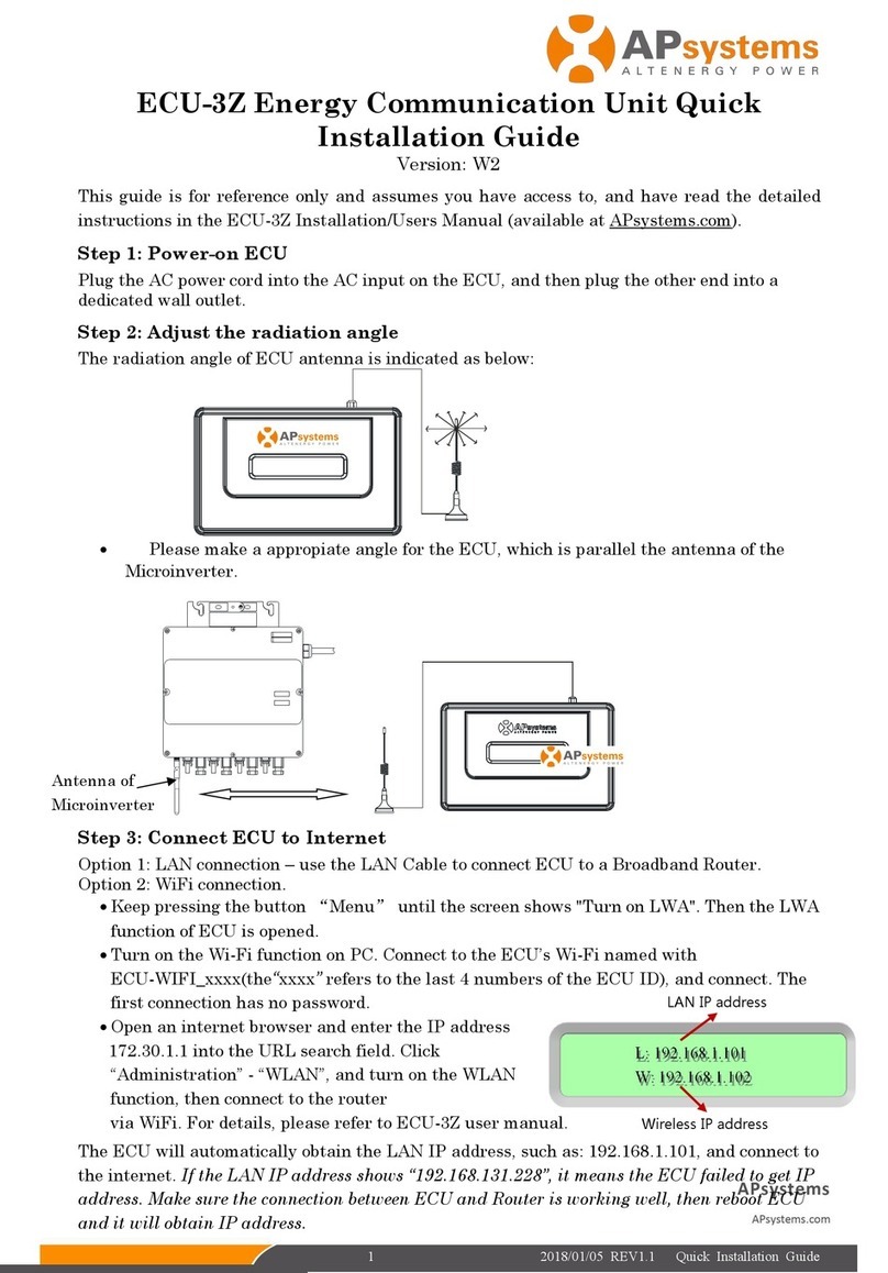
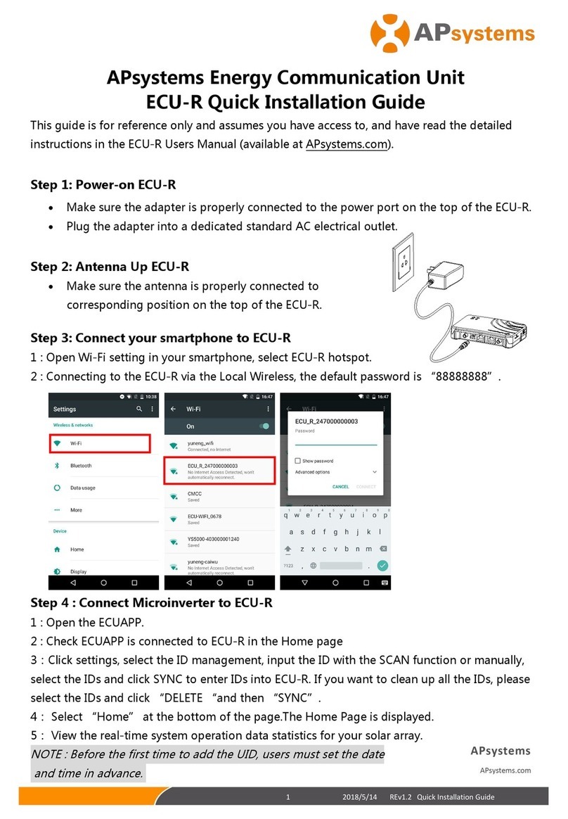
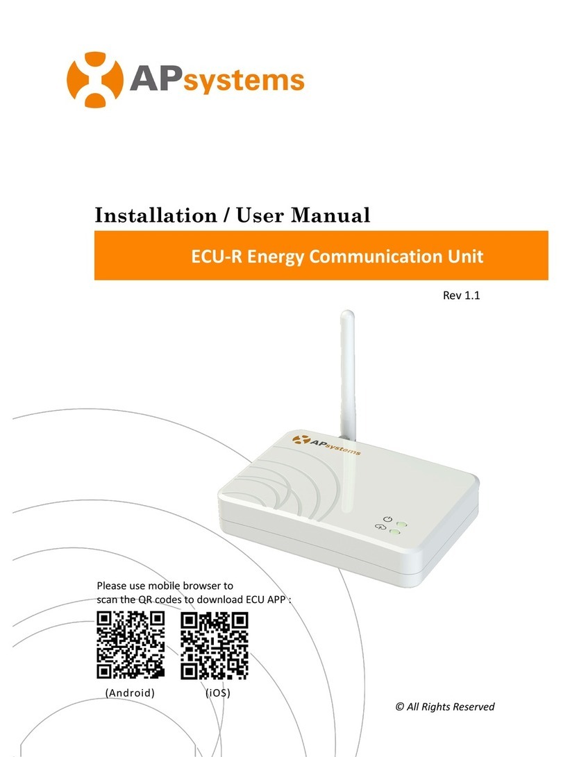
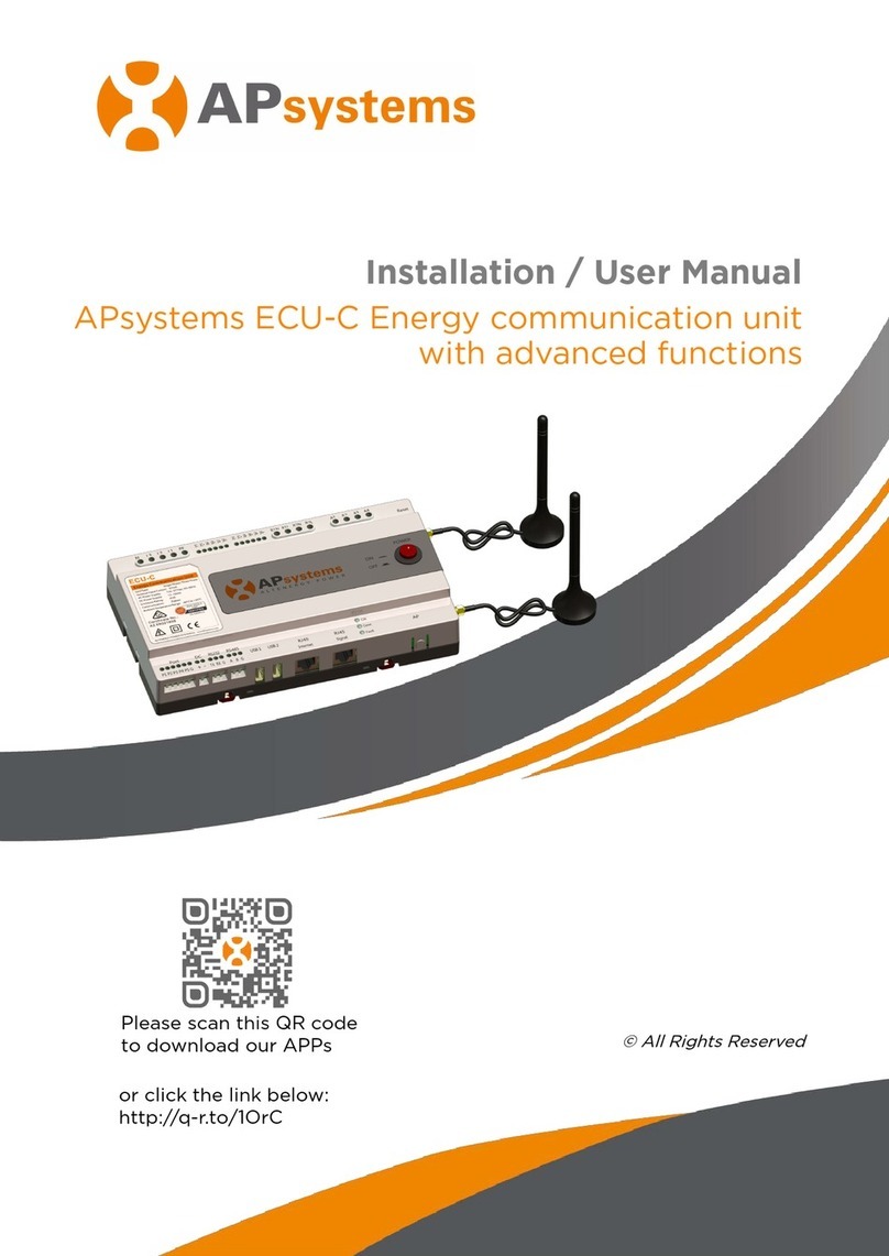
APsystems ECU-R Instruction Manual

Installation / User Manual
Rev 1.0 NA 1.0
© All Rights Reserved
APsystems ECU-R
Energy Communication Unit

APsystems ECU-R Installation/User Manual
1
Table of Contents
1. Introduction.............................................................................................................................................2
2. Interface Explanation.............................................................................................................................. 3
2.1 Interface Layout......................................................................................................... 3
2.2 Reset...........................................................................................................................3
2.3 Power Connection Port.............................................................................................. 3
2.4 USB port..................................................................................................................... 3
2.5 RJ45 Ethernet Network Port...................................................................................... 4
2.6 RJ45 Signal(Only for Australia)............................................................................. 4
2.7 Antenna......................................................................................................................4
2.8 LED1........................................................................................................................... 4
2.9 LED2........................................................................................................................... 4
3. Hardware Installation..............................................................................................................................5
3.1 Preparation................................................................................................................ 5
3.2 Selecting an Installation Location for the ECU-R....................................................... 5
3.3 Installation................................................................................................................. 5
3.4 Cable Connection....................................................................................................... 7
3.5 Antenna......................................................................................................................8
3.6 Internet Connection................................................................................................... 9
4. ECU-R User Interface............................................................................................................................. 10
4.1 Connecting to the ECU-R via the Local Wireless......................................................10
4.2 Managing IDs........................................................................................................... 11
4.3 Home Screen............................................................................................................11
4.4 Data.......................................................................................................................... 12
4.4.1 Real Time Data.............................................................................................12
4.4.2 Trend of system power................................................................................ 13
4.4.3 Power generation statistics......................................................................... 13
4.5 Settings.....................................................................................................................14
4.5.1 Managing IDs............................................................................................... 14
4.5.2 Changing the Date....................................................................................... 14
4.5.3 Managing the Network Connection............................................................ 15
4.5.4 Managing the WLAN connection.................................................................15
4.5.5 WLAN PASSWORD........................................................................................16
4.5.6 Language......................................................................................................17
4.5.7 Help..............................................................................................................17
5. Technical Data........................................................................................................................................18
6.Contact Information...............................................................................................................................20
APsystems ECU-R Installation/User Manual
2
1. Introduction
The APsystems Energy Communication Unit (ECU-R) is the information gateway for our
microinverters. The unit collects module performance data from each individual
microinverter and transfers this information to an Internet database in real time, requiring
only a single data and power cable. Through the APsystems Energy Monitoring and Analysis
software, the ECU-R gives you precise analysis of each microinverter and module in your
solar installation ECU APP. The user-friendly interface lets you access your solar array in
seconds.
Features
Collects individual module and microinverter statistics
Communicates in real time
Requires no additional wiring
The APsystems ECU-R is used in utility-interactive grid-tied
applications, and is made up of four key elements:
APsystems Microinverter
APsystems Energy Communication Unit (ECU-R)
APsystems APP (ECU APP)
Based on Android and iOS.
APsystems Energy Monitoring and Analysis (EMA)
Web-based monitoring and analysis system.
Figure 1

APsystems ECU-R Installation/User Manual
3
2. Interface Explanation
2.1 Interface Layout
The ECU-R interface includes, from left to right, are Reset,power
connection port, USB port, RJ45 Internet, RJ45 Signal port and antenna.
Reset Power Connection Port Antenna
Figure 2
2.2 Reset
Press the Reset button for three seconds or longer, and the ECU-R will
automatically return to the default settings.
The wireless password will be changed to ‘88888888’.
2.3 Power Connection Port
The power connection port connects power through the power adapter.
2.4 USB port
The USB interface is reserved.
USB port
RJ45 Signal(Only for Australia)
RJ45 Ethernet Network Port

APsystems ECU-R Installation/User Manual
4
2. Interface Explanation
2.5 RJ45 Ethernet Network Port
The ECU-R allows the user to communicate with the EMA
2.6 RJ45 Signal(Only for Australia)
The RJ45 Signal is designed for DRM0, it should be connected by RJ45 connector
in the package otherwise the inverters will not work.
2.7 Antenna
The antenna in the package should be connected to ECU-R.
Figure 3
2.8 LED1
When the ECU-R works normally, the LED1 is light.
2.9 LED2
When the ECU-R works normally, the LED2 will flicker ;
When the LED2 does not flicker the network is abnormal, please onfirm the
network connection.
.
LED1
LED2

APsystems ECU-R Installation/User Manual
5
3. Hardware Installation
3.1 Preparation
Make sure you have the following components ready before
beginning to install the ECU-R:
A dedicated standard AC electrical outlet (located
as close to the array as is possible).
A broadband Internet connection available for your use.
A broadband router with either a CAT5 Ethernet, or a wireless router.
A smart phone with ECU APP.(see page 10)
3.2 Selecting an Installation Location for the ECU-R
Choose a location that is as close to the array as possible
The ECU-R is NOT rated for outdoor use, so if installing outdoors near a junction
box or breaker panel, make sure you enclose it in an appropriate weatherproof
NEMA electrical box.
3.3 Installation
1) Using a Wall Mount
When mounting the ECU-R to a wall, make sure to select a cool, dry indoor location.
Depending on the wall surface you are mounting the ECU-R to, use either two (2)
#8 drywall screws or wall anchors, installed 100 mm apart. The drywall screws
and wall anchors are NOT included in the ECU-R kit.
Align and slide the ECU-R onto the mounting screws.
Figure 4

APsystems ECU-R Installation/User Manual
6
3. Hardware Installation
2)Power Distribution Cabinet Installation
If you use the energy communicator in power distribution cabinet:
Install the two Guide rail fasteners on the guide rail 100 mm apart .
Align and slide the ECU-R onto the two Guide rail fasteners.
Figure 5

APsystems ECU-R Installation/User Manual
7
3. Hardware Instrallation
3.4 Cable Connection
1) Using a Wall Mount
Connect the adapter to the power connection port on the top of the ECU-R.
Figure 6
2)Power Distribution Cabinet Installation
Guide rail type socket installation (The guide rail type socket is not supplied
by APsystem).
Connect the adapter to the power connection port on the top of the ECU-R.
Figure 7

APsystems ECU-R Installation/User Manual
8
3. Hardware Instrallation
3.5 Antenna
Make sure the antenna is properly connected to corresponding position on the
top of the ECU-R.
Connect the antenna to the RF port of the ECU-R,The antenna must be placed
outside the Power Distribution Cabinet.
Figure 8
Do not put the antennas inside a metal box, that will block the signal.

APsystems ECU-R Installation/User Manual
9
3. Hardware Installation
3.6 Internet Connection
There are two different approaches to connecting the ECU-R
to the Internet:
Option 1: Direct LAN cable connection.
1) Make sure the LAN cable is connected to the network
port on the bottom of the ECU-R.
2) Connect the LAN cable to a spare port on the
broadband router.
Figure 9
Option 2: Wireless Connection.
Use ECU-R internal WLAN (see Managing the WLAN Connection).

APsystems ECU-R Installation/User Manual
10
4. ECU-R User Interface
Please scan the QR code to get ECU APP :
(ios) (Android)
4.1 Connecting to the ECU-R via the Local Wireless
Open the ECU APP.
Open the WLAN, link the WiFi of ECU-R, the default password is “88888888”.

APsystems ECU-R Installation/User Manual
11
4. ECU-R User Interface
4.2 Managing IDs
Click settings, select the ID management,input the ID ,click OK to complete. If you
want to clean up all the IDs, please click “CLEAR ID “.
4.3 Home Screen
Select “Home” at the bottom of the page.
The Home Page is displayed.

APsystems ECU-R Installation/User Manual
12
4. ECU-R User Interface
Green light indicates the mobile phone is connected to the ECU-R.
Grey light indicates the mobile phone disconnects with ECU-R.
4.4 Data
4.4.1 Real Time Data
To view the real-time system operation data statistics for your solar array, click
“Real Time Data” from the ECU-R home screen to navigate to the real-time data
screen.
Click component, you can see the the specific information of the inverter,
including the inverter ID, the PV module power, voltage, frequency and
temperature.
Green panel indicates the inverter is connected.
Grey panel indicates the inverter is disconnected.

APsystems ECU-R Installation/User Manual
13
4. ECU-R User Interface
4.4.2 Trend of system power
To view the system power of any period,
click "Power" at the real-time data page.
The Trend of system power screen is displayed.
4.4.3 Power generation statistics
Press “Energy” at the real-time data page to view the system power generation of
your solar array.
The Power generation statistics screen is displayed.
Performance data for the current week:

APsystems ECU-R Installation/User Manual
14
4. ECU-R User Interface
4.5 Settings
Click on the settings
4.5.1 Managing IDs
This page reference 4.2 Managing IDs.
4.5.2 Changing the Date
It is critical for accurate power production
reporting that the ECU-R is programmed
With the correct date, time.

APsystems ECU-R Installation/User Manual
15
4. ECU-R User Interface
4.5.3 Managing the Network Connection
The default network connection setting for the ECU-R is “DHCP,” which allows the
ECU-R to automatically establish a connection assignment from the router. The
ECU-R can be assigned a static.
4.5.4 Managing the WLAN connection
Select the button next to the available network that you wish to access SSID, and
a password entry field will be displayed below the network name. Enter the
password into the password entry field.

APsystems ECU-R Installation/User Manual
16
4. ECU-R User Interface
After the password is sent, ECU-R will restart. Please reconnect to ECU-R.
4.5.5 WLAN PASSWORD
Please reconnect the ECU-R hotspot after
setting the password.On the page, you can
modify Password.
if you forget the “old password”, can be
carried out on a hardware reset ECU-R,
WiFi password recovery for the default
password is "88888888".

APsystems ECU-R Installation/User Manual
17
4. ECU-R User Interface
4.5.6 Language
Switch Language.
4.5.7 Help

APsystems ECU-R Installation/User Manual
18
5. Technical Data
Specifications subject to change without notice.
Please ensure you are using the most recent update found at www.APsystems.com.
This device complies with part 15 of the FCC Rules. Operation
is subject to the following two conditions: (1) This device may
not cause harmful interference, and (2) this device must accept
any interference received, including interference that may
cause undesired operation.
This Class B digital apparatus complies with Canadian ICES-003.
Model: ECU-R
REV 1.0
Communication Interface
Integrated Wi-Fi
802.11g/n
Antenna
Standard
Power Requirements
AC Adapter
110~240 VAC, 50~60 Hz 5V 2A
Power Consumption
1.7W
Mechanical Data
Dimensions (W×H×D)
122mm×87mmx25mm
Weight
150g
Ambient Temperature Range
-20°C to +65°C
Cooling
Nature Convection; No Fans
Enclosure Environmental Rating
Indoor - NEMA 1(IP20)
Features
Compliance
IEC 60950-1, EN60950-1, IEC 60529, EN 60529,
ANSI/UL 60950-1, CAN/CSA C22.2 No.60950-1,
UL50E, FCC part 15, EN61000-6-1,EN61000-6-3,
ICES-003, AS NZS 60950-1, GB/T17799
2017/11/25 REV1.0

APsystems ECU-R Installation/User Manual
19
5.Technical Data
Disposal of your old appliance
1. When this crossed-out wheeled bin symbol is attached
to a product, it means the product is covered by the
European Directive 2002/96/EC.
2. All electrical and electronic products should be disposed
of separately from the municipal waste stream via
designated collection facilities appointed by the
government or the local authorities.
3. The correct disposal of your old appliance will help prevent
potential negative consequences for the environment
and human health.
4. For more detailed information about disposal of your old
appliance, please contact your city office, waste disposal
service or the shop where you purchased the product.
CAUTION
The professional person is allowed to replace the battery.
Do not ingest battery,Chemical Burn Hazard.
This product contains a coin/button cell battery. If the coin/button cell battery
is swallowed, it can cause severe internal burns in just 2 hours and can lead to death.Keep
new and used batteries away from children.If you think batteries might have been
swallowed or placed inside any part of the body, seek immediate medical attention.
Other manuals for ECU-R
7
Table of contents
Other APsystems Gateway manuals

APsystems
APsystems ECU-R User manual

APsystems
APsystems ECU-C User manual

APsystems
APsystems ECU-R User manual

APsystems
APsystems ECU-3Z User manual

APsystems
APsystems ECU-3Z User manual

APsystems
APsystems ECU-3Z User manual

APsystems
APsystems ECU-R Instruction Manual

APsystems
APsystems ECU-R Instruction Manual

APsystems
APsystems ECU-B Instruction Manual