APsystems ECU-3Z User manual

Installation / User Manual
Version: W1
© All Rights Reserved
Rev 2.2
APsystems ECU-3Z
Energy Communication Unit with ZGB

APsystems ECU-3Z W1 Installation/User Manual
1
Table of Contents
Introduction............................................................................................................... 2
Interface Explanation.................................................................................................3
Interface Layout............................................................................................................... 3
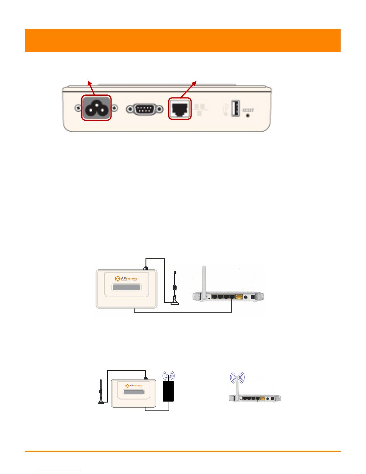
Power Connection Port.................................................................................................... 3
RS232 Serial Port..............................................................................................................3
RJ45 Ethernet Network Port............................................................................................ 4
USB Interface................................................................................................................... 4
Reset................................................................................................................................ 4
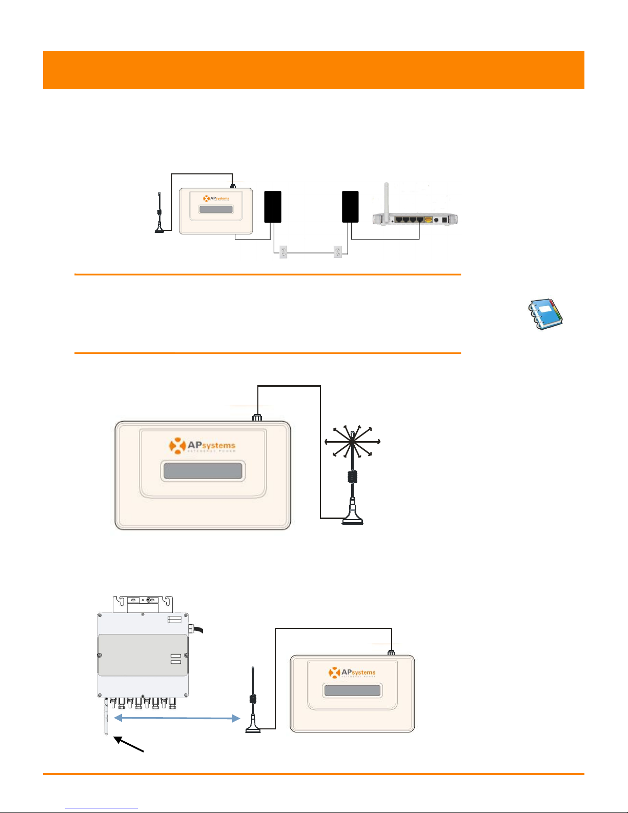
Hardware Installation................................................................................................ 5
Preparation...................................................................................................................... 5
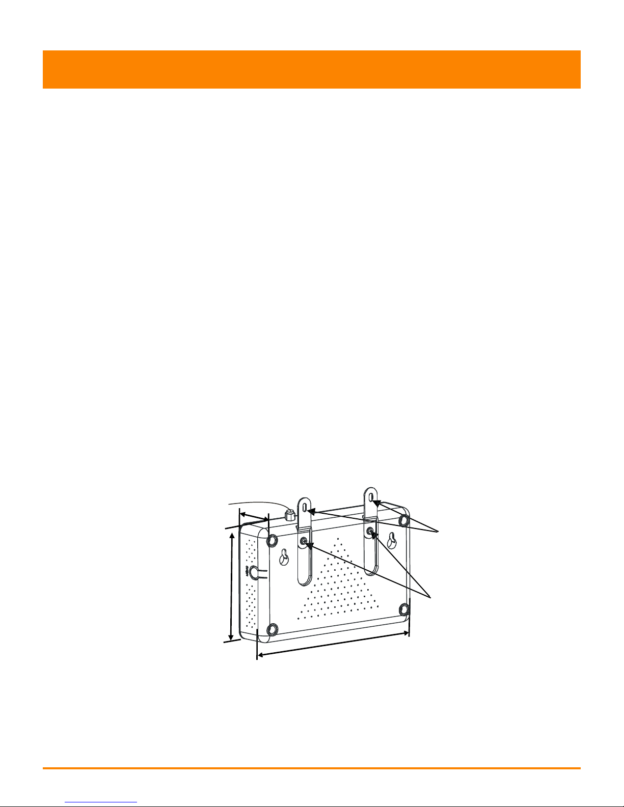
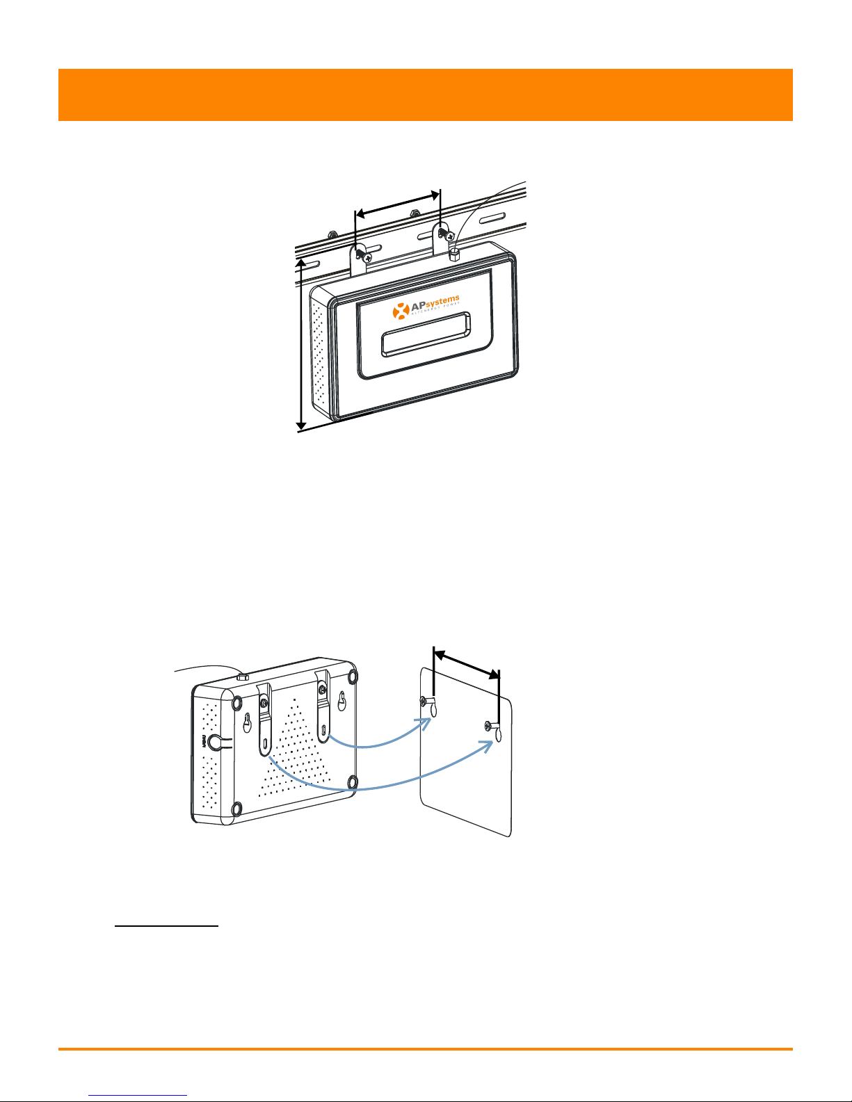
Selecting an Installation Location for the ECU.................................................................5
Cable Connections........................................................................................................... 7
Internet Connection.........................................................................................................7
The radiation angle of the ECU antenna..........................................................................8
ECU Initialization Sequence.......................................................................................9
Step 1: Power on ECU...................................................................................................... 9
Step 2: ECU time zone setting........................................................................................11
Step 3: EMA Monitoring................................................................................................ 11
Basic Operation........................................................................................................12
Menu Structure..............................................................................................................12
Restore the factory set operation..................................................................................14
Troubleshooting............................................................................................................. 14
Local Network Interface.......................................................................................... 15
Connecting to the ECU via the LAN................................................................................15
Connecting Directly to the ECU......................................................................................15
Home Screen..................................................................................................................17
Real-time Data Screen....................................................................................................18
Configuration Screen..................................................................................................... 18
Administration Screen....................................................................................................21
Remote ECU Management (EMA)........................................................................... 26
ECU Configuration/ECU Status Page..............................................................................27
Setting the ECU Time Zone............................................................................................ 28
Managing Inverter IDs and Updating the Inverter ID List..............................................28
Technical Data..........................................................................................................30

APsystems ECU-3Z W1 Installation/User Manual
2
Introduction
The APsystems Energy Communication Unit (ECU), is the
information gateway for our microinverters. The unit collects
module performance data from each individual microinverter and
transfers this information to an Internet database in real time,
requiring only a single data and power cable. Through the
APsystems Monitoring and Analysis software, the ECU gives you
precise analysis of each microinverter and module in your solar
installation from any web-connected device. The ECU’s integrated
http webserver offers the simplest and most flexible network
integration of any data logger on the market. The user-friendly
browser-based interface lets you access your solar array in seconds.
Features
Collects individual module and microinverter statistics
Communicates in real time
Requires no additional wiring
The APsystems Microinverter is used in utility-interactive grid-tied
applications, and is made up of three key elements:
APsystems Microinverter (with zigbee function)
APsystems Energy Communication Unit (ECU)
APsystems Energy Monitoring and Analysis (EMA)
web-based monitoring and analysis system
Branc h J-box
Gr ound Neutral
Meter
AC Di s tri buti on Pa nel
PV
Modul e
PV
Modul e
Microinvert er
ECU
1APsystems Microinverter
APsystems ECU
APsystems EMA
AC power line
Ethernet Router
3
2
4
5
1
2
3
45
Figure 1

APsystems ECU-3Z W1 Installation/User Manual
3
Interface Explanation
Interface Layout
The ECU interface includes, from left to right, are power
connection port, serial port, network port, USB port, and Reset.
Power Connection Port RS232 Serial port Network port USB interface Reset
Figure 2
Power Connection Port
The power connection port connects power through the power line.
Figure 3
RS232 Serial Port
You can connect a GPRS module to the RS232 serial port. Select GPRS
module to connect to the network on the “Network Connectivity” page,
and communicate with the EMA to check the system data.
Figure 4

APsystems ECU-3Z W1 Installation/User Manual
4
Interface Expalnation
RJ45 Ethernet Network Port
The ECU allows the user to communicate with the EMA, and
log in to the ECU's local page in the absence of the wired LAN
and WLAN, to set up the system and view the system data via
Ethernet network port. User can select optional WiFi-Bridge
wireless Internet.
Figure 5
USB Interface
In the case of the absence of the wired network, user can select
optional WiFi-Bridge wireless Internet. USB interface only
provides 5V DC power supply for the WiFi-Bridge.
Reset
Press the Reset button for three seconds or longer, and the ECU will
automatically return to the default settings.
NOTE: The historical power generation won't be cleared.

APsystems ECU-3Z W1 Installation/User Manual
5
113mm
182mm
42mm
Hardware Installation
Preparation
Make sure you have the following components ready before
beginning to install the ECU:
AC power line
A broadband Internet connection available for your
use.
A broadband router with either a CAT5 Ethernet, or
wireless router.
A laptop with a web browser (to view the APsystems
EMA online monitoring application).
A pre-programmed ECU.
Selecting an Installation Location for the ECU
The ECU is NOT rated for outdoor use, so if installing
outdoors near a junction box or breaker panel, make
sure that you enclose it in an appropriate weatherproof
NEMA electrical box.
1) Using an Electrical Mounting Din Rail
Loosen the two (2) M3 mounting screws on the back of
the ECU and rotate the two (2) rail holders so that the
holders are above the ECU.
Figure 6
M3 Screw
Holder

APsystems ECU-3Z W1 Installation/User Manual
6
Hardware Installation
Attach the ECU to the mounting rail with machine screws.
Figure 7
2) Using a Wall Mount
When mounting the ECU to a wall, make sure to select a
cool, dry indoor location.
Depending on the wall surface you are mounting the
ECU to, use either two (2) #8 drywall screws or wall
anchors, installed 130 mm apart. The drywall screws
and wall anchors are NOT included in the ECU kit.
Align and slide the ECU onto the mounting screws.
Figure 8
Best Practice: Install and connect the ECU to the Internet
(see instructions below) while the rest of the array is being
installed. Doing so allows the ECU to automatically update
its internal software while the rest of the physical installation
is underway. The ECU will then communicate with the inverters
when the installation is complete and the array is energized.
130mm
80 mm
138mm

APsystems ECU-3Z W1 Installation/User Manual
7
Hardware Installation
Cable Connections
Power Connection Port Network port
Figure 9
Connect the supplied power cable to the power
connection port on the bottom of the ECU.
Connect the supplied LAN cable to the network
port on the bottom of the ECU.
Internet Connection
There are three different approaches to connecting the ECU
to the Internet:
Option 1: Direct LAN cable connection.
1) Make sure the LAN cable is connected to the network
port on the bottom of the ECU.
2) Connect the LAN cable to a spare port on the
broadband router.
Figure 10
Option 2: Wireless Connection.
Using a wifi extender:
1) Make sure the LAN cable is connected to the network
port on the bottom of the ECU.
2) Connect the LAN cable into the wifi extender.
Figure 11
Option 3: Using a PLC bridge
1) Make sure the LAN cable is connected to the network
port on the bottom of the ECU.

APsystems ECU-3Z W1 Installation/User Manual
8
Hardware Installation
2) Connect the LAN cable to the “send” unit of the PLC
bridge.
3) Connect a LAN cable from the “receive” unit of the PLC
bridge to a spare port on the broadband router (refer
To the bridge users manual for specific operating instructions).
Figure 12
NOTE: 1. The ECU is NOT a wireless device and requires
a wifi extender or bridge to make the connection
to a wireless router.
2. A PLC bridge uses the power line to communicate
and requires both a “send” and “receive” unit.
The radiation angle of the ECU antenna
Figure 13
Make a appropriate angle for the ECU, which is
parallel the antenna of the microinverter
Figure 14
Antenna of
microinverter

APsystems ECU-3Z W1 Installation/User Manual
9
ECU Initialization Sequence
Once power is supplied to the ECU, it automatically steps through
a series of initialization screens on its LCD display.
LCD Display
Figure 15
Step 1: Power on ECU
As soon as the ECU is plugged into an AC outlet, the following
information will be displayed on LCD after ten seconds.
1) Loading the software firmware:
Figure 16
2) Searching for the inverters:
Firmware Version
Figure 17
IP Address
A word about network communication protocols. The ECU needs
to have access to the router via an IP address. The ECU will only
search for and obtain a Dynamic Host Configuration Protocol (DHCP)
IP address during its powering up sequence.
For example, the LCD screen on the front of the ECU displays an
IP address such as “192.168.2.101”, if the connection to the router
is successful (the IP address will vary based on the router supplier, so
check with the user manual for specifics). If, however, the LCD
displays “60.190.131.228”, the ECU-router connection has not been
successful, in which case you’ll need to check all of the cabling
connections and reboot the ECU by removing the power cable for a
few seconds and reconnecting.
Loading…
Searching W1.0
192.168.2.101

APsystems ECU-3Z W1 Installation/User Manual
10
ECU Initialization Sequence
NOTE: The complete initialization sequence can take
several minutes (up to 15 minutes depending on the
complexity of the installation).
3) Operation interface:
IP Address EMA Communication
Figure 18
Current Power Production Lifetime Production Reporting Inverters
IP Address:
The LCD screen on the front of the ECU displays an
IP address such as “192.168.2.101”, if the connection to
the router is successful (the IP address will vary based
on router supplier, so check with the user manual for
specifics). If, however, the LCD displays “60.190.131.228”,
the ECU-router connection has not been successful, in
which case you’ll need to check all of the cabling connections
and reboot the ECU by removing the power cable for a
few seconds and reconnecting.
EMA Communication:
A “+Web” indicates that the ECU is communicating with
the APsystems EMA via the Internet.
“-Web” is an indication that there is a problem and the
ECU is not communicating with the APsystems EMA.
Need to setup the security authority to offer Auto IP
configuration.
Current Power Production:
What the solar array is producing currently (in Watts).
Lifetime Production:
The lifetime power output of the system (in kWh).
Reporting Inverters:
The number of inverters reporting into the ECU. If the
number is followed by an “!”, then the number of reporting
inverters does not match the number of IDs that have been
programmed into the ECU.
NOTE: The inverter IDs must be programmed into
the ECU for the ECU to recognize the inverters. The
ECU will NOT auto-sense the inverters (see ID
Management pg. 20).
192.168.2.101 +Web
750W 11.54Kwh 12

APsystems ECU-3Z W1 Installation/User Manual
11
ECU Initialization Sequence
Step 2: ECU time zone setting
Enter the IP address shown on the ECU LCD into the
internet browser, and then open the web page.
Click “Administration”, then “Date, Time, Time zone”.
In the corresponding box, enter local date/time/time
zone, and click Update after finished. For details, refer to
time management on pg.24.
Step 3: EMA Monitoring
After the ECU displays “+Web”,contact the installer or APsystems
technical support and they will setup an EMA account with User Name
and Password, then complete EMA management(see pg.30).

APsystems ECU-3Z W1 Installation/User Manual
12
Basic Operation
The APsystems ECU has a two-line, 40-character LCD display
with alphanumerics. Set the mode using a single button.
NOTE: The ECU functions as a gateway and monitors the
microinverters that are connected to the PV modules.
Therefore, the communication between inverters and
ECU does not affect the inverters' performance, even if ECU
drops inverters. The power production data collected by
ECU is for reference only; please check the power meter
for the real power production of the whole system.
Menu Structure
You can access the ECU’s menu by pressing and holding the
Menu Button on the side of the ECU for 2 seconds.
MENU Button
Figure 19
NOTE: The Menu Button will only cycle through its menu
selections once the ECU has been successfully initialized.
The ECU has the following menu structure (displayed on LCD
screen):
Figure 20

APsystems ECU-3Z W1 Installation/User Manual
13
Basic Operation
Press and hold the MENU Button, releasing the button to gain
access to the functionality of each menu item.
Exit Menu:
Status:
Returns the ECU to the normal operating
screen (see Operating Interface, pg. 10).
Reports both the number of inverters that
should be connected to the ECU (Total), and
the number that are actually connected
(Connected). These numbers should match.
Figure 21
Turn off all: Turn off the entire system. Choose “Ok”,
and the system of inverters will be turned off.
Choose “Cancel”, and ECU will exit the menu.
Figure 22
If within one minute without pressing the button again, then
automatically exit the menu button.
NOTE: The above operation should be done under the
guidance of a support technician.
Connected: 12
Total: 15
Ok
Cancel

APsystems ECU-3Z W1 Installation/User Manual
14
Basic Operation
Restore the factory set operation
The following diagram shows the connetions on the bottom of
APsystems the ECU.
Figure 23
RESET
To restore the ECU’s factory settings, simply press the “Reset”
button for three seconds or longer. The unit will automatically
return to its default settings.
Troubleshooting
Potential Problems and Solutions
IP Address Problem: If the IP address displayed on the ECU’s
LCD does not match the subnet on your internal network and
shows “60.190.131.228”, it means that it was unsuccessful in
obtaining a DHCP IP address from your router.
Check network connectivity to the router or other
DHCP server. You may need to contact your Internet
Service Provider or refer to your router documentation
for troubleshooting assistance.
LCD Displays “-Web”: The ECU could not connect to the
APsystems website.
Check network connectivity to the router. You may
need to contact your Internet Service Provider or refer
to your router documentation for troubleshooting
assistance
LCD Display “!”: The number of installed units doesn’t match
the microinverter-count. This may indicate that the ECU is having
difficulty communicating over the power line. It could also be
caused by low sunlight, resulting in module voltage that is too
low for the microinverter to power up.
Figure 24
Plug the ECU into an electrical socket in a different
location. Keep it away from your router.
192.168.2.101 +Web
750W 11.54kWh 12!

APsystems ECU-3Z W1 Installation/User Manual
15
Local Network Interface
The ECU can be configured, and its data reviewed, by connecting
a computer to the ECU via the Local Area Network (LAN), or by
connecting directly to the ECU via its Ethernet port.
Connecting to the ECU via the LAN
1. Make sure both your computer and the ECU are correctly
connected to the LAN.
2. Using a standard web browser on your computer, enter the
IP Address that is displayed on your ECU into the URL
search field.
The ECU’s “splash” screen is displayed:
Figure 25
Connecting Directly to the ECU
Using a Windows-based PC
1. Connect the computer to the ECU using a CAT5
network cable.
2. Power up the ECU by connecting the power cable.
3. Open the “Network and Sharing Center” in the
Control Panel on the PC.
4. Select “Local Area Connection” for “Unidentified
Network”.
5. Select “Properties” when “Local Area Connection
Status” (LAC) window is displayed.
6. Highlight “Internet Protocol Version 4 (TCP/IPv4)”
when the “Local Area Connection Properties” window
is displayed.
7. Select “Use the Following IP Address” radial button
and enter the IP Address and Subnet Mask as listed
below. Do not enter anything in the DNS Server address
section.
IP Address: 60.190.131.190
Subnet Mask: 255.0.0.0

APsystems ECU-3Z W1 Installation/User Manual
16
Local Network Interface
8. Select “OK” on the IPv4 Properties window.
9. Close the LAC Properties window.
10. Close the LAC Status window.
11. Close the Network and Sharing Center.
12. Using a standard web browser on your computer,
enter the IP Address that is displayed on your ECU
into the URL search field.
The ECU’s “splash” screen is displayed.
Figure 26
Using an Apple Mac
1. Connect the computer to the ECU using a CAT5
network cable.
2. Power up the ECU by connecting the power cable.
3. Select the Apple icon in the menu bar to access
“System Preferences”.
4. Select “Network” in the “Internet & Wireless” section
of the System Preferences.
5. Select “Ethernet” on the left side of the Network
window.
6. Select “Manually” from the “Configure IPv4” dropdown
menu.
7. Enter the following in the appropriate fields:
IP Address: 60.190.131.190
Subnet Mask: 255.0.0.0
8. Leave the “Router” field blank.
9. Select “Apply”.
10. Using a standard web browser on your computer,
enter the IP Address that is displayed on your ECU
into the URL search field.

APsystems ECU-3Z W1 Installation/User Manual
17
Local Network Interface
The ECU’s “splash” screen is displayed:
Figure 27
Home Screen
Select “Home” at the top of the page.
The Home Page is displayed:
Figure 28
ECU ID:
Lifetime Generation:
Current Power:
Generation of
Current Day:
Last connection to
Website:
This is a unique number that identifies
this specific ECU.
Amount of power this system has generated
during its lifetime.
Real-time power of this system
Amount of power that has been generated
during the most current day.
The last time the ECU checked into the
central APsystems EMA database.

APsystems ECU-3Z W1 Installation/User Manual
18
Local Network Interface
Number of Inverters:
Last Number of
Inverters Online:
Current Software
Version:
Database Size:
Current Timezone:
ECU Mac Address:
Number of inverters that have programmed
into the ECU.
Number of inverters that are checking in
with the ECU.
Current version of the firmware.
Amount of data currently being stored on
the ECU.
Time zone that has been programmed into
the ECU.
The computer “machine address” of the ECU.
Real-time Data Screen
To view the real-time system operation data statistics for your solar
array, click “Real Time Data” from the ECU home screen to navigate
to the real-time data screen.
The Real Time Data screen is displayed:
Figure 29
Configuration Screen
The inverters are pre-programmed with system parameters with
factory setting, but these parameters can be changed based on
local grid and utility requirements.
WARNING: Only certified APsystems Installation
Technicians should be managing the system parameters.
Resetting these parameters incorrectly can severely affect
system performance. Contact APsystems Technical Support
BEFORE attempting to change the system parameters.

APsystems ECU-3Z W1 Installation/User Manual
19
Local Network Interface
Managing System Parameters
1) Select “Configuration” at the top of page.
2) Select “Parameters”.
The Parameters screen is displayed:
Figure 30
3) Make the parameter changes that are required.
4) Press “Save”.
It will take a few minutes for the inverter parameter changes to be
reflected in the list of inverters.
Clearing GFDI Faults
1) Select “Configuration” at the top of page.
2) Select “GFDI”.
The GFDI page is displayed:
Figure 31
3) Place a check mark in the “Clear GFDI” column for those
inverters that need to have GFDI cleared.
4) Press “Clear GFDI” button at the bottom of the page.
Other manuals for ECU-3Z
2
This manual suits for next models
1
Table of contents
Other APsystems Gateway manuals

APsystems
APsystems ECU-3Z User manual

APsystems
APsystems ECU-R Instruction Manual

APsystems
APsystems ECU-R User manual

APsystems
APsystems ECU-C User manual

APsystems
APsystems ECU-R Instruction Manual

APsystems
APsystems ECU-3Z User manual

APsystems
APsystems ECU-R Instruction Manual

APsystems
APsystems ECU-B Instruction Manual

APsystems
APsystems ECU-R User manual