manuals.online logo
Brands
  1. Home
  2. •
  3. Brands
  4. •
  5. APW Wyott
  6. •
  7. Oven
  8. •
  9. APW Wyott XWAV1417A User manual

APW Wyott XWAV1417A User manual

Other manuals for XWAV1417A

2

Other APW Wyott Oven manuals

APW Wyott CDO-18 120 User manual

APW Wyott

APW Wyott CDO-18 120 User manual

APW Wyott X*WAV 1417 User manual

APW Wyott

APW Wyott X*WAV 1417 User manual

APW Wyott RANSI/NSF4 User manual

APW Wyott

APW Wyott RANSI/NSF4 User manual

APW Wyott CDO-17 User manual

APW Wyott

APW Wyott CDO-17 User manual

APW Wyott XWAV1829 EZ SS User manual

APW Wyott

APW Wyott XWAV1829 EZ SS User manual

APW Wyott XWAV-1422EZ User manual

APW Wyott

APW Wyott XWAV-1422EZ User manual

APW Wyott QST-350E User manual

APW Wyott

APW Wyott QST-350E User manual

APW Wyott X*WAV 1422 User manual

APW Wyott

APW Wyott X*WAV 1422 User manual

APW Wyott CDO-17 User manual

APW Wyott

APW Wyott CDO-17 User manual

APW Wyott X*WAV 1422 User manual

APW Wyott

APW Wyott X*WAV 1422 User manual

APW Wyott CDO-17 User manual

APW Wyott

APW Wyott CDO-17 User manual

APW Wyott X*WAV 1417 User manual

APW Wyott

APW Wyott X*WAV 1417 User manual

APW Wyott XWAV1417A User manual

APW Wyott

APW Wyott XWAV1417A User manual

APW Wyott ECO 4000-350E User manual

APW Wyott

APW Wyott ECO 4000-350E User manual

APW Wyott X*WAV 1417 User manual

APW Wyott

APW Wyott X*WAV 1417 User manual

APW Wyott XWAV-1829EZ User manual

APW Wyott

APW Wyott XWAV-1829EZ User manual

APW Wyott XWAV1417A User manual

APW Wyott

APW Wyott XWAV1417A User manual

Popular Oven manuals by other brands

Brandt FC 222 user manual

Brandt

Brandt FC 222 user manual

aumate TOA20M04N-1E instruction manual

aumate

aumate TOA20M04N-1E instruction manual

Maytag CWE4100AC - 24" Single Electric Wall Oven Dimension Guide

Maytag

Maytag CWE4100AC - 24" Single Electric Wall Oven Dimension Guide

Kernau KBO 1076 S PT B instruction manual

Kernau

Kernau KBO 1076 S PT B instruction manual

Bosch HB 37 N Series User manual and installation instructions

Bosch

Bosch HB 37 N Series User manual and installation instructions

Electrolux EOD5420AA user manual

Electrolux

Electrolux EOD5420AA user manual

Mx Onda MX-HC2183 instruction manual

Mx Onda

Mx Onda MX-HC2183 instruction manual

Daewoo F6EV19SM2 Service manual

Daewoo

Daewoo F6EV19SM2 Service manual

Blodgett MT3870 Specifications

Blodgett

Blodgett MT3870 Specifications

GE ZET2F owner's manual

GE

GE ZET2F owner's manual

GE JK3000DF3WW owner's manual

GE

GE JK3000DF3WW owner's manual

eka EKF 523 NT Operating and instruction manual

eka

eka EKF 523 NT Operating and instruction manual

AEG Electrolux E3191-5 user manual

AEG Electrolux

AEG Electrolux E3191-5 user manual

Pratica Rocket Express quick start guide

Pratica

Pratica Rocket Express quick start guide

Viking Professional VGSO260T user guide

Viking

Viking Professional VGSO260T user guide

FM RX203 instruction manual

FM

FM RX203 instruction manual

Bosch HBN331 9B Series instruction manual

Bosch

Bosch HBN331 9B Series instruction manual

NEFF B95M42N0MK Instructions for use

NEFF

NEFF B95M42N0MK Instructions for use

manuals.online logo
manuals.online logoBrands
  • About & Mission
  • Contact us
  • Privacy Policy
  • Terms and Conditions

Copyright 2025 Manuals.Online. All Rights Reserved.

Phone: +1 (214) 421-7366
Fax: +1 (214) 565-0976
Toll Free: +1 (800) 527-2100
Website: www.apwwyott.com
E-mail: [email protected]
INSTALLATION
AND
OPERATING
INSTRUCTIONS
INTENDED FOR OTHER THAN HOUSEHOLD USE
Model: XWAV 1417A
RETAIN THIS MANUAL FOR FUTURE REFERENCE
UNIT MUST BE KEPT CLEAR OF COMBUSTIBLES AT ALL TIMES
P/N 96100010 10/07
1
PASS THROUGH OVEN
APW WYOTT
729 Third Avenue
Dallas, TX 75226
This equipment has been engineered to provide you with year-round dependable service when used
according to the instructions in this manual and standard commercial kitchen practices.
Initial heating of unit may generate smoke or fumes and must be done in a well ventilated area.
Overexposure to smoke or fumes may cause nausea or dizziness.
FOR YOUR SAFETY: Do not store or use gasoline or other flammable vapors and
liquids in the vicinity of this or any other appliance. !!
WARNING: Improper installation, adjustment, alteration, service or maintenance can
cause property damage, injury or death. Read the Installation, Operating and
Maintenance Instructions thoroughly before installing or servicing this equipment. !!
R
ANSI/NSF4
2
1. OWNER’S INFORMATION
General Information:
1. Always clean equipment thoroughly before first use. (See general cleaning instructions).
2. Check rating label for your model designation and electrical rating.
3. For best results, use stainless steel countertops.
General Operation Instructions:
1. All foodservice equipment should be operated by trained personnel.
2. Do not allow your customers to come in contact with any surface labeled “CAUTION HOT”.
3. Never touch ceramic or steel heaters.
Warranty Information:
Reliability Backed By APW Wyott’s Warranty:
All APW Wyott Pass Through Ovens are backed by a one year parts and labor warranty, including On-Site
Service calls within 50 miles of authorized service technicians.
Service Information:
Service Hotline (800) 733-2203
2. SAFETY INFORMATION
APW Wyott equipment is designed, built and sold for commercial use and should be operated by trained
personnel only. Clearly post all CAUTIONS, WARNINGS and OPERATING INSTRUCTIONS near each
unit to insure proper operation and to reduce the chance of personal injury and/or equipment damage. This
product is used for the cooking, defrosting or re-thermalization of food products only.
Always disconnect power before servicing the unit. Surfaces will remain hot after power has been turned
off. Allow unit to cool before cleaning or servicing. Never clean the unit by immersing it in water. The unit is
not protected against water jets; DO NOT CLEAN PASS THROUGH OVEN WITH A WATER JET. Always
clean equipment properly before first use.
TABLE OF CONTENTS
SECTION ITEM PAGE SECTION ITEM PAGE
1 Owner's Information 2 7 Troubleshooting 6
2 Safety Information 2 8 Preventative Maintenance Schedule 7
3 Specifications 3 9 Wiring Diagrams 7
4 Installation Instructions 3 10 Parts List & Exploded View 10
5 Operation 5 11 Warranty 12
6 Cleaning 6
!
!
WARNING: An earthing cable must connect the appliance to all other units in the complete
installation and from there to an independent earth connection.
!
!WARNING ( ): To comply with EN 61000-3-11, the system may only be connected
to a source of supply that has a system impedance of 0.2459 ohms or less.
CE units only
!
!
WARNING: In Europe, appliance must be connected by an earthing cable to all other units
in the complete installation and thence to an independent earth connection in compliance
with EN 60335-1 and/or local codes
3
3. SPECIFICATIONS
OVERALL DIMENSIONS - XWAV 1417A
D
F
GH
I
J
K
L
AC
B
E
L =
A = 24.49”
B = 21.00”
C = 15.14”
D = 18.00”
E = 14.00”
F = 11.80”
G = 10.50”
H = 17.25”
I = 38.25”
J = 3.84”
K = 18.00”
4.00”
Electrical ratings:
Power Cord:
Six (6) foot, 3 wire grounded cord. If the supply cord is damaged, the manufacturer, or an authorized
service agent, must replace it in order to avoid a hazard and warranty. Please contact the factory by
calling the 800 # located on the unit.
Shipping Weight:
XWAV 1417A 98 lbs. (44.5 kg.)
MODEL WATTS VOLTS AMPS (1 Phase) NEMA PLUG
4100 208 19.7 6-30P
4100 240 17.1 6-30P
XWAV 1417A
4. INSTALLATION INSTRUCTIONS
If the carton appears damaged, or damage is discovered once the carton is opened, stop
immediately and contact the freight company to file a damage claim.
CAUTION: The Pass Through Oven is shipped assembled. The unit is shipped with
urethane supports between the top heaters and the conveyor assembly. Please remove
all urethane supports and packaging materials before operating the unit. Failure to
remove all packaging materials may lead to a fire and / or damage to the appliance.
!
!
4
1. Remove all external packaging that is protecting top portion of unit.
2. Remove unit from shipping container while in the upright position. The unit can be lifted out of the
carton by grasping under the conveyor on each side of the appliance. Please remove the plastic
bag.
3. Remove all internal packaging to the unit. Important: Remove urethane supports located
inside the tunnel oven between the top heaters and the conveyor. Remove tape from
conveyor trays. Remove tape from extrusion corners. Remove tape from deflecting curtains
located just above entrance and exit of conveyor.
4. Visually inspect all external and internal portions of unit for damage. Important: Inspect the
top white ceramic elements located inside the oven tunnel after removal of urethane
supports. To inspect these white ceramic elements, use a small mirror held under each element to
detect cracks. Important: The Ceramic elements are fragile and will break under
stress. Do not twist, pull, push, or otherwise subject the white ceramic elements to
stress.
5. Wipe down the exterior of the unit using a damp cloth with warm water. Do not use abrasive pads or
cleaners as they will damage the stainless steel surface and high temperature plastic.
NOTE: DO NOT USE CLEANERS OF ANY KIND ON THE WHITE CERAMIC HEATERS.
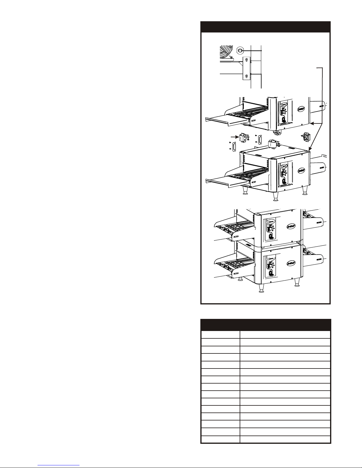
6. Remove four feet from box and install into threaded nuts located at the four corners underside of the
left and right housings; Also remove conveyor extension tray(s). Conveyor extensions should be
hung off end of conveyor frame. As our standard, Model XWAV 1417A will only have one extension
intended for the exit end.
7. Place unit in operating location.
Note: Ambient Conditions - Make sure that the operating location is in an area where the
ambient temperature is held constant (minimum 70°F). Please avoid areas such as near
exhaust fans and air conditioning ducts.
Warning: Operating environment
Ensure that operation location is at a reasonable distance from combustible walls and materials
otherwise combustion or discoloration could occur. Stand-off/Air-divider located on rear panel is
important in maintaining proper division of inlet and exhaust air flow - If removed it could result in
improper functioning of unit and MAY cause personal injury and WILL void your warranty.
Caution: Operating environment
Place unit on a stable, level counter at a convenient height for use. Turn the adjustable feet so
that unit is level to countertop. The top of the unit is not intended for use a shelf. Materials
placed there are at risk for fire.
8. Before plugging unit into wall, make sure that the switch is in the off position.
9. Warning: Ensure no hands, tools or parts or other unintended items are located on the conveyor
as injury will result when unit is turned on.
10. Plug unit into grounded electrical outlet with correct voltage, and plug configuration.
Warning: Using any receptacle that is not designed to match the attached cord and plug MAY
cause personal injury and WILL void your warranty.
IMPORTANT FOR FUTURE REFERENCE
Please complete this information and retain this manual for the life of the equipment. For
Warranty Service and/or Parts, this information is required.
Model Number Serial Number Date Purchased
5
Oven Stacking
The stacking kit will consist of 4 corner posts to be
inserted between stacked units.
Warning: When stacking, unit must have proper
stacking kit installed. This will prevent overheating
and damaging of electrical components.
Warning: Do not stack more than three units tall or do
not use more than two stacking kits.
Warning: Standoff on rear panel of unit is important
to allow proper inlet and exhaust fan airflow. Do not
cover inlet or exhaust fan openings as this could
damage electrical components.
1. Ensure bottom unit is mounted on secure
surface, with feet installed.
2. Remove respective corner end caps and
screws. This will allow each of the stacking
spacer retaining fingers to slide into the
extrusions.
3. Remove the feet from the top unit as shown.
4. Secure each stacking spacer to the bottom of
the unit as shown by using the bolts and
washers provided. You should have four total
of each.
5. Once the stacking kit spacers are secure, place
top unit onto bottom unit. The stacking kit
spacers each have tapered guides to allow the
unit to lock into position.
6. Refer to Figure 1. Install rear support bracket
and screws as shown. Each stacking kit
requires that two brackets be mounted on the
backside only. One bracket near the strain
relief and one at the opposite end.
7. Refer to Cleaning Instructions for cleaning of
stacking spacers and cleaning between units.
FIGURE 1
Remove End
Caps & Screws
Before Installing Kit
Stacking Kit
#94000189
5. OPERATION
1. The controls that operate the unit, heaters and
conveyor are located on the front left side of the
unit.
2. The On/Off switch is used to turn the unit on or off.
Once the unit is turned on the conveyor will
automatically run. Warning: Ensure no hands,
tools or parts are located on the conveyor as injury
will result when unit is turned on.
3. The control areas (EGO’s) are used to control top
and bottom heat. The controls allow for separate
upper and lower zones. The settings for the upper
and lower zones are 1 - 15; 1 being the coolest and
15 being the hottest setting.
4. Note: Before moving the On / Off switch to the “On”
position, please read the following statements:
1 28 seconds
2 29 seconds
3 32 seconds
4 43 seconds
5 52 seconds
6 1:01 minutes/seconds
7 1:16 minutes/seconds
8 1:29 minutes/seconds
9 1:45 minutes/seconds
10 2:07 minutes/seconds
11 2:44 minutes/seconds
12 3:35 minutes/seconds
13 5:26 minutes/seconds
14 9:35 minutes/seconds
15 OFF
SETTING EQUIVALENT COOK TIME
6
Caution: External Surface Temperatures
The unit's external surface temperatures will be hot. Use caution when touching these areas to
avoid injury.
Warning: Severe Burns - Ceramic Heaters
The white ceramic heaters operate at high temperatures. Do not touch elements after power
is applied to the elements. Incorporated into the front surface of the element is a red color
changing decal. As the element reaches a predetermined temperature, the decal will change
from red to black. The decal will remain black until the element falls below the transition
temperature where it will then return to its original red color. However, the element even if red
will still be extremely hot. This color changing feature is used ONLY for determining if element is
operating properly.
5. The deflector curtains located at the entrance and exit of the unit are used to contain the heat inside
the unit, as well as keep any forced drafts from entering the unit. These curtains aid in efficient
operation of the heaters and can be adjusted to increase or decrease the entrance and exit height.
These curtains should be adjusted to the minimum height required above the conveyor for the
product you are heating.
Control Operation
This oven has 2 heating zones, 1 on top, and one in the bottom. The top zone (Top Heat) is used to
control all 5 ceramic emitters. The bottom zone (Bottom Heat) is used to control the bottom element.
6. CLEANING
Insure the appliance has been turned off and has had sufficient time for all surfaces to cool down before
cleaning. Use only mild soap and water to clean this appliance. Appliance cleaning should be performed daily.
NOTE: DO NOT USE ABRASIVE PADS OR CLEANING SOLUTIONS ON THIS APPLIANCE.
Daily Cleaning
Remove the crumb pans and wipe out debris with a damp rag and mild soap solution.
Remove the deflector panels located at the entrance and exit of the oven tunnel. Wipe down the area
under the deflector panels, and the deflector panels, with a damp rag and mild soap. Reinstall the
deflector panels by reversing the procedure used to remove them.
Using a damp rag with mild soap and water, wipe down the exterior surfaces of the appliance.
Using a damp rag with mild soap solution, wipe down all areas of the conveyor. DO NOT ATTEMPT TO
CLEAN THE UPPER WHITE CERAMIC, OR LOWER METAL HEATERS.
When units are in the stacked configuration, it is still necessary to clean between the units. Using a
damp rag with mild soap and water, wipe down the tops and undersides of all units. Ensure there are no
foreign objects between the units that could catch fire.
Using a damp rag with mild soap and water, wipe the surfaces of the stacking spacers on all four
corners.
7. TROUBLESHOOTING
Always ask and check the following:
Not getting power:
1. Is the unit connected to a live power source of the proper voltage?
2. Check the rating label. Is the unit connected to the correct power source?
3. Check the circuit breaker.
4. If the above checks out, and you still have problems, call your local service agent.
7
Conveyor not working:
1. Please refer to “Not getting power” section.
2. Is the knob turned to correct setting per desired speed?
3. Note: At slower settings the conveyor moves very slow and may appear stalled, which is not the
case.
4. If the above checks out, and you still have problems, call your local service agent.
Food not cooking properly:
1. Please refer to “Not getting power” section.
2. Are the controller and speed control adjusted to the desired setting?
3. Are the deflector curtains in the proper position?
4. If the above checks out, and you still have problems, call your local service agent.
Please follow the cleaning section for the daily preventative maintenance schedule.
DO NOT USE ABRASIVES OR CLEANING SOLUTIONS ON THIS APPLIANCE.
Routinely check before every operation that adequate distance is allowed between fans and
anything that would possibly allow foreign debris or substances to be taken in by inlet fan.
Clean fan guards on a daily basis to ensure proper inlet cooling to electrical components and
efficient hot air exhaust.
On a daily basis make sure side walls of tunnel oven remain clean to assist in maintaining even
cooking around product. Be careful not to bump or hit the upper ceramic heaters when wiping
down.
Ensure belt is properly tensioned as to prevent slippage or binding, which causes strain on motor.
DO NOT ATTEMPT TO MAINTENANCE, SERVICE OR CLEAN THE UPPER CERAMIC AND LOWER
METAL HEATERS.
8. PREVENTATIVE MAINTENANCE SCHEDULE
OVERHEAD
7 TO: EGO- H2
12
2
1
7
8
8 TO: EGO- H1
9. WIRING DIAGRAMS
8
UNDER CARRIAGE
RIGHT SIDE HOUSING
RED TO "LI" ON SWITCH
BLACK TO "L2" ON SWITCH
MOTOR SPEED POT.
1155
B
BLACK
BLACK
LUE
RED
BLACK
RED
ORANGE
BLACK
BLUE
GREEN
ORANGE
BELT
REVERSING
SWITCH
24
VDC
OUTPUT
+
POWER
SUPPLY
-
208
VAC
INPUT
DRIVE
MOTOR
GREEN
GREEN
ORANGE
INSULATED
CONNECTOR
RED
SCOTCHLOK
1 2 3
WHITE
WHITE
RIGHT
SIDE
HOUSING
POWER SWITCH
OFF
ON
MOTOR SPEED POT.
5
7
11
6
ORANGE
GREEN
BLUE
L1 L2
L2
L1
15
GR
15
8
87
9
9
14
11
12 12
10
10
14
13
13
BLUE
GREEN
ORANGE
BLACK TO "N" ON 3 PIN
POWER SUPPLY
5 TO "LI" ON 2 POLE TERMINAL BLOCK
6 TO "L2" ON 2 POLE TERMINAL BLOCK
RED TO "L" ON 3 PIN
POWER SUPPLY
ORANGE TO "ORANGE" ON ON P/S 6 PIN HARNESS
GREEN TO "GREEN" ON P/S 6 PIN HARNESS
BLUE TO "BLUE" ON DRIVE MOTOR HARNESS
7 TO "L1" ON CERAMIC TERMINAL BLOCK
8 TO "L2" ON CERAMIC TERMINAL BLOCK
ATTACH
GROUND
WIRE
TO
SWITCH
&
EGO
PROTECTOR
HOUSING
9
LEFT SIDE HOUSING
L2
TAT
H
L1
L1
L2
T.S
GR
TAT
ORD
CK
E
ON SWITC
ITCH
L2
L1
33
3
6
5
6
4
T.S
POWER C
L1= BLA
L2= WHIT
4
5
5 TO "LI"
6
TO
"L2" ON SW
10
ITEM PART NUMBER DESCRIPTION QUANTITY
10. PARTS LIST & EXPLODED VIEW
PARTS LIST
ELEMENT, CERAMIC, 208V1 94000028 AS R'QD
94300001 ELEMENT, CERAMIC, 240V AS R'QD
FIREBAR ELEMENT, XWAV1417, 208V
294100016 1
94400001 FIREBAR ELEMENT, XWAV1417, 240V 1
396100001 ESCUTCHEON, XWAV 1417A 1
496100002 WELD ASSY, CONVEYOR, XWAV 1417A 1
END, CAP, F/L & B/R
593000067 4
END CAP, B/L & F/R
693000070 4
782914 CHAIN, CONVEYOR DRIVE, XWAV1417, 1422, 1829 1
WIRE BELT, XWAV1417 & 1422
894100043 1
994200097 ASSY, MERKLE-KORFF GEAR MOTOR 1
10 94200095 KIT, POWER SUPPLY, 5V/24V OUTPUT 1
11 95000033 TERMINAL BLOCK, CERAMIC AS R'QD
12 85283 FAN CORD 2
13 85287 FAN GUARD 2
14 85284 FAN,COOLING 2
15 30203 TERMINAL BLOCK, 2 POLE 1
16 86295 LEG, BLACK 4
17 94000105 THERMOSTAT 2
18 94100048 POWER CORD, 12/3, 6-30P 1
19 96100010 INSTALLATION/OPERATION MANUAL, XWAV 1417A 1
20 67002 SWITCH, ON-OFF, 30 AMP, DPST 1
21 88705 KNOB, BLACK 3
22 94100029 TRAY, CONVEYOR, XWAV 1417 2
23 94100045 CONVEYOR, EXTENSION, XWAV 1417, XWAV 1422 AS R'QD
24 69104-EGO 208V INFINITE CONTROL-EGO 1
26 94000189 STACKING BRACKET KIT (OPTIONAL) 1
27 94000172 ASSY, POTENTIOMETER 1
28 96100007 PROTECTOR, EGO SWITCH 1
25 89408 SWITCH, LIGHTED ROCKER 1
69103-EGO 240V INFINITE CONTROL-EGO 1