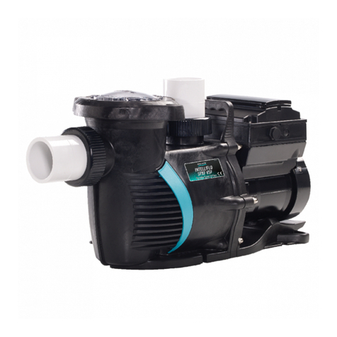
AQUA FORTE GFVS19N User manual

INVERTER POOL PUMP
Model: GFVS19N
Thank you for purchasing our variable speed pool pumps, this manual contains
important information that will help you in operating and maintaining this product. Please
read the manual carefully before installation & operation and retain it for future reference.

EN
CONTENTS
1. IMPORTANT SAFETY INSTRUCTIONS......................................................1
2. TECHNICAL SPECIFICATIONS ..................................................................1
3. OVERALL DIMENSION...............................................................................2
4. INSTALLATION............................................................................................2
5. SETTING & OPERATION............................................................................4
6. WIRING CONNECTION ..............................................................................6
7. EXTERNAL CONTROL(Not included in standard model).......................7
8. TROUBLE SHOOTING................................................................................8
9. ERROR CODE.............................................................................................9
10. MAINTENANCE.......................................................................................10
11. WARRANTY & EXCLUSIONS .................................................................10
12. WEEE LEGISLATION..............................................................................10

1
1. IMPORTANT SAFETY INSTRUCTIONS
This guide provides installation and operation instructions for this pump. Consult your supplier
with any questions regarding this equipment.
1.1 When installing and using this electrical equipment, basic safety precautions should
always be followed:
•RISK OF ELECTRICAL SHOCK. Connect only to a branch circuit protected by a ground-fault
circuit-interrupter (GFCI). Contact a qualified electrician if you cannot verify that the circuit is
protected by a GFCI.
•This pump is for use with permanent installed in ground or above ground swimming pools and
may also be used with hot tubs and spas if so marked. Do not use with above ground pools
that can be readily disassembled for storage.
• The pump is not submersible.
• Before servicing the pump; switch off power to the pump by disconnecting the main circuit to
the pump.
• Never open the inside of the drive motor enclosure.
1.2 All installations must be fitted with earth leakage or residual current protection
devices, having a rated residual operating current not exceeding 30mA.
WARNING:
•Do not run the pump dry. In case of dry run, mechanical seal will be damaged and the pump
will start leaking. Fill the pump with water before starting.
• Before servicing the pump, switch OFF power to the pump by disconnecting the main circuit
to the pump and release all pressure from pump and piping system.
• Never tighten or loosen screws while the pump is operating.
• Do not block the pump suction.
2. TECHNICAL SPECIFICATIONS
Model
Advised pool
volume
(m³)
P1
Voltage/Ph
Current
Backwash
Circulation
kw
A
Qmax
Hmax
at 6m
at 8m
at 10m
GFVS19N
40~80
0.13~1.0
220-240/1
1.30~7.29
33.7
21
8.16~24
8.5~20.5
7.1~16.3

2
3. OVERALL DIMENSION
GFVS19N
4. INSTALLATION
4.1. Pump Location
1.Locate pump as close to pool as practical and run suction lines as direct as possible to
reduce friction loss.
2.To avoid direct sunshine or heat, It is recommended to place pump indoor or in the shade.
3.Do NOT install pump in a damp or non-ventilated location. Keep motor clean. Pump motors
require free circulation of air for cooling.
4.2. Piping
1). For improved pool plumbing, it is recommended to use a larger pipe size. When installing
the inlet and outlet fittings (male adaptor), use thread sealant.
2). Piping on the suction side of the pump should be the same or larger than the return line
diameter.
3). Plumbing on the suction side of the pump should be as short as possible.
4). For most installations we recommend installing a valve on both the pump suction and return
lines so that the pump can be isolated during routine maintenance. However, we also
recommend that a valve, elbow or tee installed in the suction line should be no closer to the
front of the pump than five times the suction line diameter.
4.3. Valves and Fittings
1). Do not install 90° elbows directly into pump inlet. Elbows should be no closer than 250mm
to the inlet. Joints must be tight. Suction line diameter must equal or be larger than the
discharge line diameter.

3
2). Flooded suction systems should have gate valves installed on suction and discharge pipes
for maintenance, however, the suction gate valve should be no closer than five times the suction
pipe diameter as described in this section.
3). Use a check valve in the discharge line when using this pump for any application where
there is significant height to the plumbing after the pump.
4). Be sure to install check valves when plumbing in parallel with another pump. This helps
prevent reverse rotation of the impeller and motor.
ELBOW
250mm
Suction
63mm
Return to pool 63mm

4
5. SETTING & OPERATION
5.1 Interface
Manual Mode
Timer Mode
Backwash Mode
Description
On/off
Lock/Backwash:
When the screen is locked, press >3
seconds to unlock the screen;
When the screen is unlocked, press it
for backwash mode.
Up: Increase value(capacity& time)
Down: Decrease value(capacity& time)
Timer: Switching from manual to Timer
mode
Capacity:40~100%
5.2 Capacity Setting
Note: The inverter module can be operated manually or automatically at regular intervals.
The system automatically saves the 4 latest valid settings.
NO.
Buttons Used
Comments
1
Press >3 seconds to unlock the screen;
Press <3 seconds for backwash mode;
Under backwash mode, pump will count down in 180s, use or to adjust
backwash time from 30-900s.
2
Press the button to start. The pump will run at full capacity (100%) .
3
Use or to adjust by 5% to a specific running capacity if needed.

5
5.3 Timer Setting
*Overlap setting of time will be considered as invalid, the pump will only run based on the
previous valid setting.
*During timer setting, if you want to return to the previous setting, hold for3 seconds.
5.4 Parameter Setting
Under OFF mode, hold for 3 second to enter parameter settings.
Parameter
Description
Default Setting
Setting Range
1
Di2
100%
40%~100%, by 5% increments
2
Di3
80%
3
Di4
40%
1.enter timer setting
2.set current time
3.to next time
4.decide the specific capacity
5.repeat above steps to set other
3timers
6.hold 3 seconds to save setting
7.check 4 timers to make sure there
is no invalid setting

6
6. WIRING CONNECTION
Warning:
All electrical wiring MUST conform with applicable National Electrical Safety Code
(NESC) and National Electric Code (NEC).
Please refer to the below schematic for information on how to correctly install your pump.
AC power input
Power source
220~240VAC, 1ph, 50Hz
Breaker
(Customer prepare)

7
7. EXTERNAL CONTROL(Not included in standard model)
External control can be enabled via following contacts. Pressing on/off can stop the pump even
if working via an external controller.
a. Digital Input:To enable external speed control, connect one of the digits from Di1/2/3/4
to COM. See schematic as below:
b. Relay Output: Connect terminal L & N to enable external control. An additional on-off is
necessary while bearing power is less than 500W (2.5A). See schematic as below:
Control system digital input

8
c. RS485: To enable external control pump running capacity, connect terminal A and B, via
Modbus485 communication protocol.
8. TROUBLE SHOOTING
Problem
Corrective solution
Pump Does Not Start
•Power Supply fault, disconnected or defective wiring
• Fuses blown or thermal overload open
• Check the rotation of the motor shaft for free movement and
lack of obstruction.
• Motor windings burned out.
Pump Won't Prime
•Empty pump/strainer housing. Make sure the pump/strainer
housing is filled with water and the cover o ring is clean.
•Loose connections on the suction side.
•Strainer basket or skimmer basket loaded with debris.
•Suction side clogged.
Low Water Flow
•Pump is not primed
Relay external control output
Display board
RS485

9
•Air entering suction piping
•Basket full of debris
•Inadequate water level in pool
Pump being noisy
•Air leak in suction piping, cavitations caused by restricted or
undersized suction line or leak at any joint, low water level in
pool, and unrestricted discharge return lines.
• Disassemble pump, clean impeller, follow pump service
instructions for reassembly.
•Vibration due to improper mounting, etc.
9. ERROR CODE
Note:
1. AL01 is not an error indication: when it appears the inverter will automatically switch to a
lower capacity to self protect against high internal temperature. When the temperature drops
back to 68℃the inverter will resume at the preset speed.
2. When causes for E002/E101/E103 lifts, the device will resume working automatically,
however when it appears a fourth time, the device will stop working, to resume operation,
unplug the device and plug in & restart again.
Item
Code
Description
Analysis
1
E001
Abnormal input voltage
Not faulty
2
E002
Output over current
Not faulty
3
E101
Heat sink over heat
Contact your supplier
4
E102
Heat sink sensor error
Contact your supplier
5
E103
Master driver board error
Contact your supplier
6
E201
Circuit board error
Contact your supplier
7
E202
Master board EEPROM reading failure
Contact your supplier
8
E203
RTC time reading error
Contact your supplier
9
E204
Display board EEPROM reading failure
Contact your supplier
10
E205
Communication error
Contact your supplier
11
AL01
Auto speed reduction against high temperature
Contact your supplier

10
10. MAINTENANCE
Emptying the strainer basket, the basket should be inspected frequently through the
transparent lid and emptied when a build-up of rubbish is evident. The directions below
should
be followed:
1. Switch off pump.
2. Unscrew the strainer basket lid anti-clockwise and remove.
3. Remove the strainer basket by lifting upwards from its housing.
4. Empty the trapped refuse from the basket. Hose out with water if necessary.
NOTE: Do not knock the plastic basket on a hard surface as it will cause damage.
5. Check the strainer basket for cracks, replace the basket in the pump if OK.
6. Replace the lid and ensure that it seals on the large rubber O-ring. Firm hand tightness
only is required.
NOTE: Failure to undertake regular maintenance may cause damage not covered by
warranty.
11. WARRANTY & EXCLUSIONS
Should a defect become evident during the term of warranty, at its option, the manufacturer
will repair or replace such item or part at its own cost and expense. Customer will need to
follow the warranty claim procedures in order to obtain the benefit on this warranty.
Under no circumstances should the manufacturer be held liable for any consequences
resulting from inappropriate, incorrect installation, or mismatching of the product to pool
pumps that are not compatible.
12. WEEE LEGISLATION
When disposing the product, please hand it over to a designated collection
point for the recycling of waste electrical and electronic equipment.
The separate collection and recycling of waste equipment at the time of
disposal will help ensure that it is recycled in a manner that protects human
health and the environment. Contact your local authority for information on
where you can drop off your water for recycling.

INVERTER ZWEMBAD POMP
Model: GFVS19N
Wij danken u voor de aankoop van deze zwembadpomp met variabele snelheid.
Deze handleiding bevat belangrijke informatie die u zal helpen bij het in gebruik nemen en
onderhouden van het product. Lees de handleiding zorgvuldig door alvorens u de pomp
installeert en bewaar deze handleiding goed voor gebruik in de toekomst.

NL
INHOUD
1. BELANGRIJKE VEILIGHEIDSINFORMATIE EN INSTRUCTIES..................1
2. TECHNISCHE SPECIFICATIES.................................................................. 1
3. AFMETINGEN.............................................................................................2
4. INSTALLEREN............................................................................................ 2
5. INSTELLINGEN EN IN GEBRUIK NEMEN VAN DE POMP .......................4
6. AANSLUIAANSLUITSCHEMA EN BEKABELING VAN DE POMP ............. 6
7. EXTERNE AANSTURING............................................................................7
8. PROBLEEMOPLOSSINGEN........................................................................8
9. ERROR MELDINGEN...................................................................................9
10. ONDERHOUD ...........................................................................................10
11. GARANTIEBEPALINGEN ..........................................................................10
12. WEEE CERTIFICERING............................................................................10

1
1. BELANGRIJKE VEILIGHEIDSINSTRUCTIES
Deze handleiding bevat installatie- en bedieningsinstructies voor de geleverde pomp.
Raadpleeg uw leverancier bij eventuele vragen met betrekking tot de pomp en de installatie
ervan.
1.1 Bij het installeren en het gebruik van het elektrische apparaat, moeten de volgende
basis voorzorgsmaatregelen in acht worden genomen:
•GEVAAR VOOR ELEKTRISCHE SCHOK. Sluit de pomp alleen aan op een systeem voorzien
van een aardlekschakelaar. Neem contact op met een elektricien wanneer u niet kunt
controleren of beslissen dat het circuit wordt beschermd door een aardlekschakelaar of u
wanneer u onzekerheden of problemen ondervindt met het installeren van de pomp.
•Deze pomp is geschikt voor permanent gebruik; bij zwembaden geïnstalleerd in de grond of
bovengronds. En kan ook gebuikt worden bij Spa’s en Hottubs indien aangegeven. Niet
gebruiken bij baden, welke bovengronds worden opgesteld en jaarlijks worden afgebroken en
opgeslagen.
•De pomp is niet waterproof en onder water op te stellen. Dit kan ernstige schade aan de pomp
maar ook mensen en omgeving ten gevolge hebben. Stel de pomp altijd op een droge plaats
op!
•Voor u onderhoud pleegt aan de pomp, schakelt u altijd eerst de stroom naar de pomp af.
•Open nooit de binnenkant van de aandrijfmotor behuizing.
1.2 De installatie moet voorzien zijn van een aardlekstroom of reststroom beveiliging,
met een nominale reststroom welke NOOIT de 30mA zal overstijgen.
WAARSCHUWING:
•Laat de pomp NOOIT droog draaien/lopen. Dit zal de mechanische seal beschadigen en
ervoor zorgen dat de pomp zal gaan lekken. Vul de pomp altijd met voldoende water alvorens
u de pomp start!
•Alvorens u onderhoud pleegt aan de pomp schakelt u altijd eerst de stroom/elektriciteit naar
de pomp toe uit en zorgt u ervoor dat de druk uit het leidingsysteem en de pomp is
verdwenen.
•Draai NOOIT (losse) schroeven van en op de pomp aan wanneer deze in bedrijf is! Schakel
altijd eerst de elektriciteit uit.
•Zorg ervoor dat de aanzuig van de pomp NOOIT wordt geblokkeerd en altijd vrij is om water
aan te zuigen!

2
2. TECHNISCHE SPECIFICATIES
3. AFMETINGEN
GFVS19N
4. INSTALLATIE
4.1 Pomp Locatie
1. Plaats de pomp zo dicht mogelijk bij het zwembad als mogelijk is en zorg ervoor dat de aan-
en afvoerleidingen tussen het zwembad en de pomp zo kort mogelijk zijn en met zo min
mogelijk bochten en aftakkingen. Dit om drukverlies zoveel mogelijk te beperken
2.Om te voorkomen dat de pomp vol in de zon komt te staan of te warm kan worden, plaatst
u de pomp het beste in een technische ruimte of in de schaduw.
3.Installeer de pomp NIET in een vochtige of slecht geventileerde ruimte. Houdt de motor
schoon. De pompmotoren hebben schone circulerende lucht nodig voor koeling!
4.2 Leidingen
1). Voor een beter leidingsysteem bij zwembaden is het aan te bevelen een grotere
leidingdiameter te gebruiken. Wanneer u de fittingen in de pomp draait maak dan altijd gebruikt
van afdichtingstape.
2). De leiding aan de aanzuigzijde van de pomp moet altijd groter of minimaal gelijk zijn dan de
leiding aan de retourzijde van de pomp.
3). De leidingen aan de aanzuigzijde dienen zo kort mogelijk te worden gehouden.
4). In de meeste installaties raden wij u aan de pomp in een bypass te plaatsen met enkele
Model
Geadviseerd
poolvolume
(m³)
P1
Stroomvoor
ziening
(V/Fase)
Ampère
Backwash
Circulatie
kW
A
Max.
flow
Max.
Hoogte
at 6m
at 8m
at 10m
GFVS19N
40~80
0.13~1.0
220-240/1
1.30~7.29
33.7
21
8.16~24
8.5~20.5
7.1~16.3

3
kranen, zodat u de pomp geïsoleerd kan worden van de hoofdleiding. Dit maakt het
eenvoudiger om periodiek onderhoud uit te kunnen voeren. Wij adviseren u ten alle tijde dat de
minimale afstand waarop een kraan, knie of T-stuk in de aanzuigleiding voor de pomp wordt
geplaatst; nooit dichter bij de aanzuig is dan 5x de diameter van de zuigbuis. Voorbeeld: Dus
bij 50mm altijd minimaal 250mm ertussen!.
4.3 Kranen en fittingen
1). Installeer NOOIT een 90 graden knie direct op de aanzuigzijde van de pomp. Knieën
mogen nooit dichter bij de inlaat geplaatst worden dan op 250mm voor de pomp. De
verbindingen moeten goed vast (gedraaid) zitten. De leiding aan de aanzuigzijde van de
pomp moet altijd groter of minimaal gelijk zijn dan de leiding aan de retourzijde van de pomp.
2). Bij pompen die onder water niveau staan, dienen altijd kranen of schuifafsluiters te worden
geplaatst voor het kunnen plegen van onderhoud. Zorg er echter wel voor dat deze op een
afstand van de pomp worden geplaatst van minimaal 5x de leidingdiameter.
3). Gebruik een terugslagklep in de afvoerleiding wanneer de pomp wordt gebruikt in een
toepassing waarbij na de pomp grote hoogten in de leiding moeten worden overbrugt.
4). Zorg ervoor dat u terugslagkleppen installeert wanneer de pomp parallel met een andere
pomp installeert. Dit helpt voorkomen dat de rotor en motor niet omgekeerd gaan draaien.
Retour naar
zwembad 63 mm
250mm
Bocht
Aanvoer 63 mm

4
5. INSTELLINGEN EN IN GEBRUIK NEMEN VAN DE POMP
5.1 Gebruikersinterface
Handmatige
modus
Timer
modus
Backwash
Modus
Beschrijving
Aan/uit
Lock/ Terugspoel:
Als het scherm is vergrendeld, drukt u > 3
seconden om het scherm te ontgrendelen; Als het
scherm ontgrendeld is, drukt u erop voor de
terugspoelmodus.
Omhoog: Waarde verhogen (capaciteit of tijd)
Omlaag: Waarde verlagen (capaciteit of tijd)
Timer: Om te schakelen tussen de handmatige en
Timer modus
Capaciteit:40~100%
5.2 Capaciteitsinstelling
Opmerking: De invertermodule kan met regelmatige tussenpozen handmatig of automatisch
worden bediend. Het systeem slaat automatisch de 4 laatste geldige instellingen op.
Nr.
Benodigde
knoppen
Opmerkingen
1
Druk > 3 seconden om het scherm te ontgrendelen;
Druk <3 seconden voor terugspoelmodus;
In de terugspoelmodus telt de pomp af in 180 seconden, gebruik of
om de terugspoeltijd aan te passen van 30-900 seconden.
2
Druk op de knop om te starten. De pomp draait op volle capaciteit (100%) .
3
Gebruik de en knoppen om de snelheid van de pomp in stappen van 5% te
verhogen of te verlagen naar de voor u gewenste snelheid.

5
5.3 Timer instellingen
*Overlappende tijdvakken worden door de pomp als niet juist gezien. De pomp zal dan draaien
op de eerste ingestelde en juiste instelling.
*Wanneer u tijdens de instellingen het Timer instellingen menu wil verlaten drukt u voor langer
dan 3 seconden op:
5.4 Parameter instellen
Druk, wanneer de pomp in de “OFF-Modus” staat, tegelijkertijd de knoppen
voor 3 seconden in, om in de parameterinstellingen te komen.
Parameter
Beschrijving
Standaard
Instellingen
Mogelijke instellingen
1
Di2
100%
40%~100%, in te stellen in stappen
van 5%
2
Di3
80%
3
Di4
40%
1.Ga naar Timer instellingen
2. Stel de huidige tijd in
3. Ga naar de volgende tijd
4. bepaal de specifieke capaciteit
5. Herhaal bovenstaande stappen om 3
andere timers in te stellen
6.Houd 3 seconden ingedrukt om op te
slaan
7 controleer de 4 timers. of er geen
incorrecte instellingen zijn gemaakt

6
6. AANSLUITSCHEMA EN BEKABELING VAN DE POMP
Waarschuwing:
Alle elektrische bedrading moet voldoen aan de geldende National Electrical Safety Code (NESC)
en de National Electric Code (NEC). En aangesloten worden volgens alle, in het land van
installatie, geldende wetgeving voor het aansluiten en bekabelen van elektrische apparaten.
Raadpleeg het schema hieronder voor meer informatie over hoe u uw pomp correct dient te installeren.
AC stroomaansluiting
Motorbeveiliging
(Door klant te voorzien)
Krachtbron
220~240VAC, 1fase, 50Hz
Aarding
Table of contents
Languages:
Other AQUA FORTE Swimming Pool Pump manuals
Popular Swimming Pool Pump manuals by other brands
Pentair
Pentair WHISPERFLO VS 1500 owner's manual
Pentair Pool Products
Pentair Pool Products Eagle owner's manual
COMFORTPOOL
COMFORTPOOL BASIC 6 manual
Bestway
Bestway FlowClear 58145 owner's manual

Elecro Engineering
Elecro Engineering Swimming Pool Heat Pump Owner's installation & operations manual

Intex
Intex Krystal Clear C600 owner's manual

STA-RITE
STA-RITE MAX-E-PRO owner's manual

Pahlen
Pahlen EcoVISE user manual

Ribimex
Ribimex Ribiland PRSWIM370/1 instruction manual

Pentair
Pentair Sta-Rite EcoSelect Enviromax 800 owner's manual

SunSun
SunSun CPP Series Operation manual

Dankoff Solar Products
Dankoff Solar Products SunCentric P instruction manual