AquaTools 3/4 HP User manual

SWIMMING POOL OR SPA PUMPS
O W N E R’ S M A N U A L
INSTALLATION, OPERATION & PARTS
MODELS
3/4 HP AT210701
1 HP AT211001
1-1/2 HP AT211501
© 1997. Printed in U.S.A AT237 (Rev. 8/22/97)
This manual should be furnished to the
end user of this system; its use will re-
duce service calls and chance of injury
and will lengthen system life.
Aquatools
293 Wright Street, Delavan, WI 53115
North America: 800-752-0183, FAX 800-582-2217
International: 414-728-5551, FAX: 414-728-4461, TELEX: ITT 4970245

2
SWIMMING POOL PUMPS
To avoid unneeded service calls, prevent possible injuries, and get the most
out of your pump and filter, READ THIS MANUAL CAREFULLY!
The Aquatools self-priming centrifugal pump is designed to be used as a fil-
tration or circulation system pump for in-ground swimming pools, spas, hot
tubs, and solar systems.
Is designed to eliminate corrosion of parts under normal pool usage and
maintenance.
Is an excellent performer, durable, reliable, with non-clogging impeller.
For other applications of pump, consult the manufacturer.
Table of Contents
Safety Instructions..........................................................................................3
Installation .................................................................................................4-5
Electrical....................................................................................................5-6
Operation...................................................................................................6-7
Pump Service.............................................................................................7-8
Storage/Winterizing.......................................................................................8
Troubleshooting Guide..................................................................................9
Repair Parts List...........................................................................................10
Warranty......................................................................................................11

3
This is the safety-alert symbol. When you see
this symbol on your valve or in this manual, look
for one of the following signal words and be alert to
the potential for personal injury.
warns about hazards that will cause se-
rious personal injury, death or major property damage
if ignored.
warns about hazards that can cause seri-
ous personal injury, death or major property damage
if ignored.
warns about hazards that will or can
cause minor personal injury or property damage if ig-
nored.
The label NOTICE indicates special instructions
which are important but not related to hazards.
Carefully read and follow all safety instructions in
this manual and on system.
Keep safety labels in good condition.
Replace missing or damaged safety labels.
Incorrectly installed or tested equip-
ment may fail, causing severe injury or
property damage. Read and follow in-
structions in owner's manual when installing and op-
erating equipment. Have a trained pool professional
perform all pressure tests.
1. Do not connect system to a high pressure or city
water system.
2. Use equipment only in a pool or spa installation.
3. Trapped air in system can cause explosion. BE
SURE all air is out of system before operating or
testing equipment.
Before pressure testing, make the following safety
checks:
• Check all clamps, bolts, lids, and system acces-
sories before testing.
• BE SURE all air is out of system before testing.
• Tighten Aquatools trap lids to 30 ft. lbs. (4.1 kg-cm)
torque for testing.
• Water pressure for test must be less than 25 PSI
(172 kPa).
• Water temperature for test must be less than 95˚ F.
(35˚ C).
• Limit test to 24 hours. After test, visually check sys-
tem to be sure it is ready for operation. Remove
trap lid and retighten hand tight only.
NOTICE: These parameters apply to Aquatools equip-
ment only. For non-Aquatools equipment, consult
manufacturer.
IMPORTANT SAFETY
INSTRUCTIONS
Always follow basic safety precautions with this
equipment, including the following.
To reduce the risk of injury, do not permit
children to use this product unless they are closely
supervised at all times.
This pump is for use with permanently
installed pools and may also be used with hot tubs and
spas if so marked. Do not use with storable pools. A
permanently installed pool is constructed in or on the
ground or in a building such that it cannot be readily
disassembled for storage. A storable pool is con-
structed so that it may be readily disassembled for stor-
age and reassembled to its original integrity.
SAVE THESE
INSTRUCTIONS
Hazardous voltage.
Can shock, burn,
or cause death.
BEFORE WORKING
ON PUMP OR MOTOR:
Unplug pump motor.
Hazardous suction.
Can trap or tear
hair or body parts,
causing severe injury
or death.
Do not block pump
suction or pool main
drain.
READ AND FOLLOW SAFETY INSTRUCTIONS!

GENERAL
Pump has been carefully assembled, tested, inspected and
packed at our factory. Note any damage to product on de-
livery ticket and file claim promptly with carrier or store of
purchase.
INSTALLATION
Locate pump as close as possible to pool (no more than
8 ft. above pool water level).
For ease of pump/motor removal, install pipe unions on
suction and discharge pipes close to pump.
Pump mount must:
Be solid-level-rigid-vibration free. (To reduce vibration
and pipe stress, bolt pump to mount.)
Allow pump suction inlet height at or below water level
in pool.
Allow use of short, direct suction pipe (to reduce friction
losses).
Allow for gate valves in suction and discharge piping.
Have adequate floor drainage to prevent flooding.
Be protected from excess moisture.
Allow adequate access for servicing pump and piping.
NOTICE: Use Teflon tape or Plasto-Joint Stik for making
all threaded connections to pump. Do not use pipe
dope; it will cause stress cracking in pump.
NOTICE: Pump suction and discharge connections have
molded-in thread stops. DO NOT try to screw pipe in
beyond these stops. Tighten pump/trap fittings only as re-
quired to ensure tight connection (1-1/2 turns past hand
tight). Do not overtighten. Use care when using teflon
tape as friction is reduced considerably; do not over-
tighten connections or damage may occur.
Teflon Taping Instructions:
Use only new or clean PVC pipe fittings.
Wrap male pipe threads with 1 to 2 layers of teflon tape,
winding tape clockwise as you face start of thread.
Cover entire threaded portion of pipe.
DO NOT OVERTIGHTEN or tighten past thread stop in
pump port!
If leaks occur, remove pipe, clean old tape, rewrap with
one to two additional layers of tape and remake connec-
tion.
NOTICE: Support all piping connected with pump!
PIPING
For pump discharge use 1-1/2" PVC pipe or reinforced
hose.
For pump suction on all models, use 1-1/2" reinforced
hose.
Increase size if a long run is needed. For pipe larger than
port, use reducing fitting in trap port.
To avoid pump strain, support suction and discharge in-
dependently. Place supports near pump.
To avoid strain left by a gap at last connection, start all
piping at pump and run pipe away from pump.
Never use suction pipe smaller than pump suction con-
nections.
No air leaks in suction pipe. Keep pipe straight. Suction
pipe inlet must be lower than pump inlet port. (Fig. 3).
NOTICE: To prevent flooding when removing pump
from service, all flooded suction systems must have gate
valves in suction and discharge pipes.
Use expansion joint or flexible piping. (Plastic pipe will
expand and contract as temperature changes.)
4
Bonding Lug
1-1/2" Discharge Piping Strainer Basket Cover
1-1/2" Suction
Piping
Drain Plugs
Figure 1
To separation tank
or waste Pool Drain
Line
Return line to pool
Skimmer
Pool water
Figure 2 – Typical In-Ground Pool Installation
Use teflon tape or
pipe joint compound
approved for use on PVC.
No air leaks.
835 0993
Figure 3 – Suction Pipe Must Not Leak

5
FITTINGS
Fittings restrict flow. Use fewest possible fittings.
Avoid fittings that could cause an air trap.
Pool and spa fittings must conform to International
Association of Plumbing and Mechanical Officials
(IAPMO) standards.
Use a non-entrapping suction fitting in pool or double
suction (skimmer and main drain).
ELECTRICAL
Ground motor before
connecting to electrical
power supply. Failure to
ground pump motor can
cause serious or fatal electri-
cal shock hazard.
Do not ground to a gas
supply line.
To avoid dangerous or
fatal electrical shock,
turn OFF power to motor
before working on electrical
connections.
Ground Fault Circuit
Interrupter (GFCI) trip-
ping indicates electrical problem. If GFCI trips and
won't reset, consult electrician to inspect and repair
electrical system.
Fire hazard. Match supply voltage to motor name-
plate voltage.
WIRING
Pump must be permanently connected to circuit. Match
wire and circuit breaker sizes to Table I. If other lights or
appliances are also on the same circuit, be sure to add
their amp loads to pump amp load. (If unsure how to do
this or if this is confusing, consult a licensed electrician.)
Use the load circuit breaker as the master on-off switch.
Install a Ground Fault Circuit Interrupter (GFCI) in cir-
cuit; it will sense a short-circuit to ground and discon-
nect power before it becomes dangerous to pool users.
For size of GFCI required and test procedures for GFCI,
see manufacturer’s instruction.
In case of power outage, check GFCI for tripping (which
will prevent normal water circulation). Reset if neces-
sary.
NOTICE: If you do not use conduit when wiring motor,
be sure to seal wire opening on end of motor to prevent
dirt, bugs, etc., from entering.
Use wire rated at 75°C, 300 volt min. on all models.
VOLTAGE
Voltage at motor must not be more than 10% above or
below motor nameplate rated voltage or motor may
overheat, causing overload tripping and reduced compo-
nent life. If voltage is less than 90% ore more than 110%
of rated voltage when motor is running at full load, con-
sult licensed electrician.
Values in Table I are for PUMP MOTOR ONLY. If addi-
tional accessories are installed on pump motor circuit
(heater, blower, etc.), include amperage draw when fig-
uring wire and circuit breaker sizes.
WARNING
Hazardous voltage. Can
shock, burn, or cause
death.
Ground pump before con-
necting to power supply.
A
B
L2
L1
A
B
L2
L1
To convert dual-voltage motors
from 230 to 115 Volts:
Move white wire w/black
tracer from B to A.
Move black wire
from A to L1.
A
B
L2
L1
A
B
L2
L1
Clamp
power
cable
to prevent
strain on
terminal
screws.
White w/
Black Tracer
Black
Motor Ground
Screw
Connect ground wire
to motor ground screw
as shown.
Connect power supply wires
to the terminal board
as shown.
Ground
Wire
1410 1194
PUMP MAX. LOAD BRANCH FUSE DISTANCE IN FT. (SERV. TO MOTOR)
MODEL HP VOLTAGE AMPS RATING AMPS* 0-100'(0-30m) 101-200'(31-60m) 201-300'(61-90m)
AT210701 3/4 115 10.2 15 14 (2mm2) 10 (5.5mm2) 8 (8.4mm2)
3/4 230 5.1 15 14 (2mm2) 14 (2mm2) 14 (2mm2)
AT211001 1 115 12.6 20 12 (3mm2) 10 (5.5mm2) 8 (8.4mm2)
1 230 6.3 15 14 (2mm2) 14 (2mm2) 14 (2mm2)
AT211501 1-1/2 115 16 25 12 (3mm2) 8 (8.4mm2) 6 (14mm2)
1-1/2 230 8 15 14 (2mm2) 14 (2mm2) 12 (3mm2)
TABLE I - WIRING CHART - RECOMMENDED FUSING AND WIRING DATA
}
Wire
Size
AWG
(mm2)
Figure 4
Disconnect power from
motor.
Move white wire w/black
tracer from B to A.
Move black wire
from A to L1.

6
GROUNDING (Fig. 5)
Permanently ground motor; use size and type wire re-
quired by code.
Ground connection must be made to green grounding
screw under motor canopy or access plate.
Connect motor ground terminal to electrical service
ground.
BONDING (Fig. 5)
'Bonding' connects all metal parts around a swimming
pool with a 'Bonding Wire' to form one unit so that in
case of short or ground, there will be no electrical cur-
rent flow between them. Bonding is not the same as
grounding.
Bonding reduces the chance of receiving an electrical
shock from metal parts of pool structure.
Follow all local and national code requirements for
bonding swimming pools, spas, hot tubs, etc.
Make all bonding connections as bare metal-to-metal
clamped or soldered connections.
Install and bond pump according to local codes and or-
dinances; use bonding lug on motor. Use solid copper
conductor No. 8 AWG (8.4 mm2) or larger.
Connect No. 8 AWG (8.4 mm2) solid copper bonding
wire to pressure wire connector on motor housing and
all metal parts of swimming pool, spa, etc., metal piping
or conduit within 5 ft. (1.5m) of inside walls of swim-
ming pool, spa, etc.)
OPERATION
NEVER run pump dry.
Running pump dry may
damage seals, causing leak-
age and flooding. Fill pump
volute and trap with water
before starting motor.
Do not add chemicals to
pool/spa system directly
in front of pump suction.
Adding undiluted chemicals
may damage pump and voids
warranty.
Before removing trap
cover:
1. STOP PUMP before proceeding.
2. CLOSE GATE VALVES in suction and discharge pipes.
3. RELEASE ALL PRESSURE from pump and piping sys-
tem.
If pump is being pressure tested, be sure trap cover
has been tightened to 30 ft. lbs. (4.1 kg-cm). The
trap pressure will release itself if cover is loosened.
Do not block pump suction. To do so with body
may cause fatal injury. Small children using pool
must ALWAYS have close adult supervision.
NOTICE: Do not block pool return or spa jets. To do so
may flood area causing damage to equipment and sur-
rounding area.
PRIMING PUMP
Open gate valves before starting system.
Release all air from filter and piping system. See filter
owner's manual.
In a flooded suction system (water source higher than
pump), pump will prime itself when suction and dis-
charge valves are opened.
If pump is not in a flooded suction system, unscrew and
remove trap cover; fill trap and pump with water.
Clean and lubricate trap cover O-ring with petroleum
jelly each time it is removed.
Clean and inspect O-ring; reinstall on trap cover.
Replace trap cover on trap; turn clockwise to tighten
cover.
NOTICE: Tighten trap cover by hand only (no wrench-
es). Use a wrench only if necessary to remove lid.
Pump should prime. Priming time will depend on verti-
cal length of suction lift and horizontal length of suction
pipe.
If pump does not prime within ten minutes, stop motor
and determine cause. Be sure all suction and discharge
Hazardous suction.
Can trap hair or body
parts, causing severe in-
jury or death.
Do not block suction.
Figure 5 – Typical ground screw and bonding lug
locations.
Bonding
Lug
Motor Nameplate
Green
Ground
Screw
Motor
Canopy
Through
Bolts 349 0893

7
valves are open when pump is running. See Trouble-
shooting Guide.
POOL, SPA OR TUB WATER
Keep water level 2" (5cm) above bottom of skimmer
opening when system is not in use. Failure to do so can
allow air to enter system, causing pump to lose its prime.
Keep water temperature at 104°F (40°C) or below for
spas/tubs and 80°F (27°C) for pools.
If uncertain, start at lower temperature and increase it
according to your experience.
Keep thermometer in pool/spa. Check it before getting
in.
Keep pool water balanced. Maintain water pH between
7.2 and 7.6.
Do not use or allow use of spa/pool by
anyone using alcohol or drugs. Effects of hot water, al-
cohol and/or drugs can cause dizziness, loss of con-
sciousness, or heart attack.
PUMP SERVICE
Pump should only be serviced by qualified
personnel.
Be sure to prime pump before starting up after service.
Before removing trap cover or front plate bolts:
1. STOP PUMP before proceeding.
2. CLOSE GATE VALVES in suction and discharge pipes.
3. RELEASE ALL PRESSURE from pump and piping sys-
tem.
To avoid dangerous or fatal electrical
shock hazard, turn OFF power to motor before working
on pump or motor!
Aside from lubricating trap cover O-Ring, no lubrication
or regular maintenance is needed beyond reasonable
care and periodic cleaning of the trap basket.
If shaft seal is worn or damaged, repair as follows:
Pump disassembly/Removing Old Seal:
Disconnect power supply to motor.
1. Disconnect electrical wire at motor. Close any gate
valves in the suction and discharge piping. Drain
pump. Remove pump hold down bolts. Disconnect
pipe unions or clamps adjacent to pump. Withdraw
complete pump/motor assembly.
2. Remove 6 screws (Key No. 3, Page 10) and withdraw
tank body (Key No. 18, Page 10). Remove tank body
O-Ring.
3. Remove motor canopy from end of motor to expose
shaft and electrical components.
4. Place 7/16” open end wrench on flats of motor shaft
at cover end below centrifugal switch mechanism.
Hold shaft, and when looking at impeller, (Key No. 8,
Page 10) turn impeller counter-clockwise and remove
from shaft.
5.Unscrew four through-bolts under motor canopy to re-
move seal plate from motor. See Figure 6.
6. Remove rotary portion of seal (Key No. 6, Page 10)
from impeller sleeve. See Figure 7.
7. Remove diffuser, (Key No. 7, Page 10).
8.Remove stationary components of seal (Key No. 6,
Page 10) from seal plate. See Figure 8.
9.Clean seal cavity in seal plate and clean motor shaft.
Pump Reassembly/Installing New Seal:
1. Carefully examine the tank body O-Ring and rubber
cup of seal (Key No. 5, Page 10). Replace if material
shows any sign of damage or deterioration.
2. Check the mechanical seal (Key No. 6, Page 10) for
scoring on the contact surfaces and also for any dam-
age to the spring or retainer. Replace seal if necessary.
3. Press the stationary components of the seal (rubber
cup and ceramic seat) into the seal plate (Key No. 4,
Page 10) using index finger pressure only. Make sure
components are firmly and evenly seated.
See Figure 9.
4. Align the tounge on the diffuser with the groove in the
seal plate (Key No. 4, Page 10) and install the diffuser
(Key No. 7, Page 10).
5. Slide the rotary portion of the seal (Key No. 6, Page
10) over the sleeve of the impeller (Key No. 8, Page
10) until it butts against the impeller shroud. See
Figure 7.
6. Insert the impeller sleeve through the opening in the
Figure 6 Figure 7 Figure 8 Figure 9

8
seal plate (Key No. 4, Page 10).
7. Install the slinger (2) on the end of the impeller sleeve.
8. Steps (3) through (7) result in subassembly of seal
plate, diffuser, impeller, seal and slinger (Key Nos. 4,
7, 8, 6, and 2 respectively, Page 10). Attach the sub-
assembly to the motor as follows:
i. Fit impeller sleeve over motor shaft.
ii. Align motor throughbolts with mounting holes in
seal plate (Key No. 4, Page 10).
iii. Insert a screwdriver in a slot at end of motor shaft
to prevent it from turning and screw on impeller
(Key No. 8, Page 10).
iv. Secure the four motor throughbolts making sure
that the seal plate (Key No. 4, Page 10) butts firmly
against the motor endbell.
9. Install the tank body O-Ring (Key No. 5, Page 10) in
the recess in the seal plate (Key No. 4, Page 10).
10. Fit the tank body (Key No. 18, Page 10). Install and
tighten six capscrews (Key No. 3, Page 10).
11. Replace motor canopy. Re-install pump. Re-connect
union couplings and electrical wiring.
STORAGE/
WINTERIZING
To prevent damage to components from fumes,
store pool and spa chemicals away from pump and
spa. If possible, store chemicals in another well-venti-
lated room.
Allowing pump to freeze will damage pump and void
warranty.
Drain all water from pump and piping when expecting
freezing temperatures or when storing pump for a long
time (see instructions below).
Keep motor dry and covered during storage.
To avoid condensation/corrosion problems, do not cover
or wrap pump with plastic.
For outdoor /unprotected pump installations:
1. Enclose entire system in a weatherproof enclosure.
2. To avoid corrosion damage, allow ventilation; do not
wrap system in plastic.
Pump down water level below all inlets to the pool.
Follow pool/spa manufacturer’s directions for storage of
pool or spa.
NOTICE: Do not use anti-freeze solutions (except propy-
lene glycol) in your pool or spa system. Most anti-freezes
are highly toxic and may damage plastic components in
the system. Propylene glycol is non-toxic and will not
damage pump components.
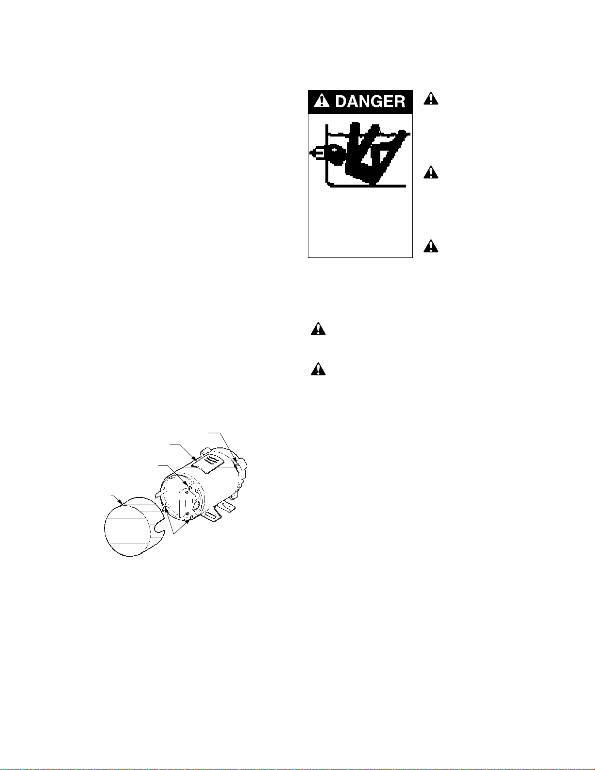
DRAINING PUMP
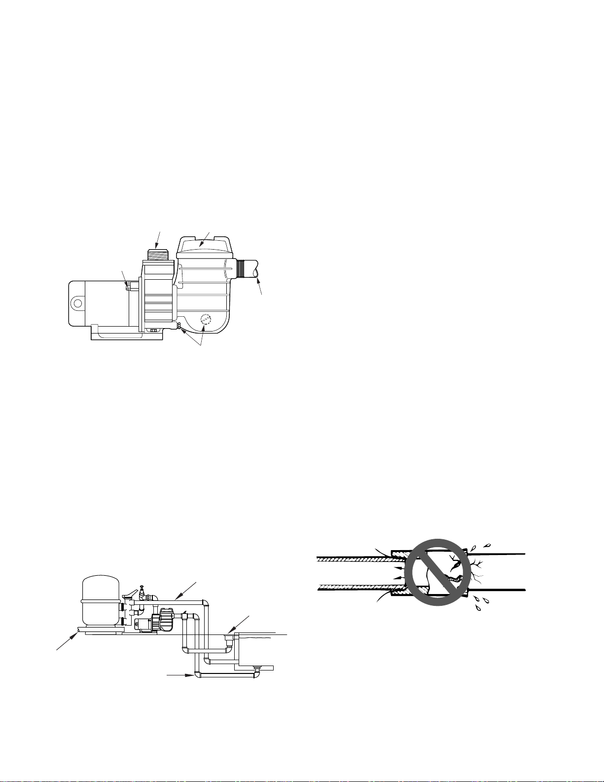
Explosion hazard. Purging the system with
compressed air can cause components to explode, with
risk of severe injury or death to anyone nearby. Use
only low pressure (below 5 PSI), high volume blower
when air purging the pump, filter, or piping.
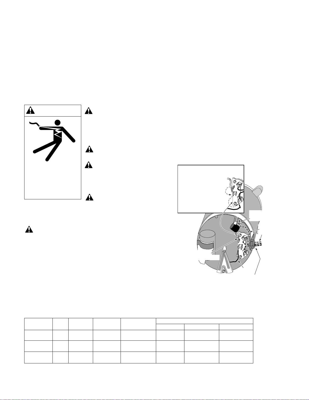
Dangerous or fatal electrical shock haz-
ard, turn OFF power to motor before draining pump.
1. Close all valves on suction and return piping.
2. Remove drain plug in bottom of volute.
3. Drain all piping and storage tanks exposed to freezing
temperatures.
A. Gravity drain system as far as possible.
B. Protect areas which retain water with non-toxic
propylene glycol antifreeze (“RV antifreeze”).
4. Be sure no airlocks are holding water in the system.
5. To prevent pump from freezing, remove trap cover
and drain the tank body through the drain plug, Key
No. 12, Page 10). Use a lid wrench to remove trap
covers that have been overtightened or have taken a
set and cannot be removed by hand. Clean pump
thoroughly. Replace trap cover.
6. Before restarting, replace all plugs and make sure all
pipe connections are tightly sealed.
Startup for winterized equipment
1. Remove any temporary weather protection placed
around system for shutdown.
2. Follow filter manufacturer’s instructions for reactiva-
tion of the filter.
3. Inspect all electrical wiring for damage or deteriora-
tion over the shutdown period. Have a qualified ser-
viceman repair/replace wiring as needed. Inspect and
tighten all watertight connections.
4. Open all valves in suction and return piping.
5. Remove all winterizing plugs from system.
6. Remove all anti-freeze solutions from system.
7. Close all drain valves and replace all drain plugs in
system.
8. Prime plug according to instructions on Page 6.

9
Only qualified personnel should electrically test
pump motor.
DISCONNECT POWER TO MOTOR BEFORE
WORKING ON PUMP. Close suction and dis-
charge gate valves.
PUMP LOSES PRIME / SUCTION LEAKS
1. Make sure there are no leaks in suction piping. Trap
lid cover must be air tight.
2. Inspect trap O-ring for cuts or nicks. Replace if neces-
sary. Lubricate with petroleum jelly before installa-
tion.
3. Make sure suction pipe inlet to pump is well below
water level to prevent pump from sucking air.
4. Replace suction trap gasket if defective.
5. Suction lift of 8 - 10' (2.4 - 3m) will reduce perfor-
mance. Suction lift in excess of 10' (3m) will prevent
pumping and cause pump to lose prime. Move pump
closer (vertically) to water source. Check size of suc-
tion pipe.
PUMP DOES NOT OPERATE
1. Check and clean suction trap, impeller, fittings, or
trap strainer.
2. Check and clean pool filter.
3. Check for worn impeller or diffuser and replace.
4. Make sure gate valves are fully open.
5. Suction piping is too small.
6. Motor internal thermal overload protector is open.
Motor runs too hot. Turn power to motor off. Check
for proper voltage.
7. Check GFCI for proper operation according to GFCI
manufacturer's instructions.
CIRCUIT BREAKER TRIPS REPEATEDLY
1. Breaker must be of adequate capacity.
2. For GFCI breaker, test according to GFCI manufactur-
er's instructions.
3. Make sure no other appliances or lights are on circuit.
4. Make sure there is only one GFCI on the circuit.
MECHANICAL TROUBLES / NOISE
1. Make sure suction and discharge piping are sup-
ported.
2. Securely mount pump on concrete platform for qui-
etest performance.
3. Air leak in suction line. Repair leak and tighten trap
lid.
4. Check and clean debris in pump impeller.
5. Cavitation -
Remove suction flow restrictions.
Increase pipe size.
Decrease number of fittings in suction piping.
Reduce flow by throttling discharge gate valve.
ELECTRICAL
1. Pump may be running too slowly; check voltage at
motor terminals and at meter while pump is running.
If low, see wiring instructions or consult power com-
pany. Check for loose connections.
2. Pump may be too hot.
A. Check line voltage. If less than 90% or more than
110% of rated voltage, consult a licensed electri-
cian.
B. Increase ventilation.
C. Reduce surrounding temperature.
D.Tighten any loose connections.
3. Motor internal thermal overload protector is open.
Motor runs too hot. Turn power to motor off. Check
for proper voltage. Check for proper impeller or im-
peller rubbing.
4. Consult dealer/installer or service representative.
TROUBLESHOOTING GUIDE

10
228 0893
1
1A 1B 23
4567
89
10
11
12
13
14
15
16
17
18
19
20
21
22
AQUATOOLS POOL PUMP
3/4 through 1-1/2 HP Models
•Not illustrated
Key Part Part
No. Description Qty. No.
1 Motor 1 Chart at Right
1A Screw, #10-32x1/2” 1 U30-692SS
1B Bonding Lug 1 U17-568
2 Water Slinger 1 C69-23
3 Capscrew, #10-24x5/8” Lg. 6 U30-152SS
4 Seal Plate 1 17140-0012
5 “O” Ring 1 17140-0026
6 Shaft Seal 1 U9-358SS
7 Diffuser 1 17140-0007
8 Impeller 1 Chart at Right
9 Trap Cover 1 C3-139P1
10 Trap Cover O-Ring 1 U9-229
11 Trap Basket 1 C108-33P
12 Drain Plug 1/4” NPT w/O-Ring 1 U178-920P
13 Flat Washer 5/16” 8 U43-41SS
14 Capscrew, 5/16-18x1-1/4” 4 U30-64SS
15 Lock Washer 5/16” 4 U43-11SS
16 Trap Body 1 C153-53P1
17 Drain Plug 1 WC78-40T
18 Gasket 1 C20-123
19 Tank Body 1 C276-57P
20 Bolt 3/8-16x1” Lg. 2 U30-74SS
21 Base 1 16920-0015
22 Flat Washer 3/8” SS 2 U43-42SS
• Voltage Sticker-115/230 Volts 1 U27-153
• Tag, “CAUTION-trap
threading, teflon tape, etc 1 C63-13
• Tag, “CAUTION/Warning
Bonding 1 C63-12
• Nameplate 1 U33-123
• Decal for pool/spa 1 U27-635
Model Motor No. Impeller No.
No. HP (Key No. 1) (Key No. 8)
115/230 Volt
AT210701 3/4 A910DL C105-226PB
AT211001 1 A910EL C105-226PC
AT211501 1-1/2 A910FL C105-226PD
For complete suction trap, order Pkg. 115.
Parts are common to all models listed
except as noted:
Key Nos. 1, Motor; and 8, Impeller are listed below.
Repair Parts

▲Retain Warranty Certificate (upper portion) in a safe and convenient location for your records.
DETACH HERE: Fill out bottom portion completely and mail within 10 days of purchase/installation to:
▼ AquaTools, Attn: Warranty Dept., 293 Wright St., Delavan, WI 53115
Pumps, filters, skimmers, underwater lights (except bulbs),
accessories and fittings manufactured by AquaTools are war-
ranted to be free of defects in material and workmanship for
one (1) year from date of installation.
Product specific warranties: Year from date
of installation
HRPB, DEPB and System 3 – Tanks. . . . . . . . . . . . 10 years
Internal filter components and valves . . . . . . 1 year
Automatic Pool Cleaners including Hose . . . . . . . 2 years
Cristal-Flo filters – Tanks. . . . . . . . . . . . 10 years pro-rated*
Valve and internal components. . . . . . . . . . . . 1 year
Posi-Flo II – Tanks. . . . . . . . . . . . . . . . . . . . . . . . . . 10 years
Elements . . . . . . . . . . . . . . . . . . . . . . . . . . . . . 1 year
Waterford Sand – Tanks. . . . . . . . . . . . . 10 years pro-rated*
Pumps. . . . . . . . . . . . . . . . . . . . . . . . . . . . . . . 1 year
Valve and Internals . . . . . . . . . . . . . . . . . . . . . 1 year
Waterford Cartridge – Filter Tank . . . . . . . . . . . . . 10 years
Pumps. . . . . . . . . . . . . . . . . . . . . . . . . . . . . . . 1 year
System 3 Above Ground Systems – Tanks . . . . . . . 10 years
Pumps. . . . . . . . . . . . . . . . . . . . . . . . . . . . . . . 1 year
Platform and Internals. . . . . . . . . . . . . . . . . . . 1 year
Pumps . . . . . . . . . . . . . . . . . . . . . . . . . . . . . . . . . . . . . 1 year
When equipped with A.O. Smith
2-compartment motors (Does not include
pumps sold as part of a systems package). . . 2 years
The foregoing warranties relate to the original consumer
purchaser (“Purchaser”) only. AquaTools shall have the op-
tion to repair or replace the defective product, at its sole
discretion. Purchasers must pay all labor and shipping
charges necessary to replace the product covered by this
warranty. Requests for warranty service must be made
through the installing dealer. This warranty shall not apply to
any product that has been subject to negligence, misappli-
cation, improper installation or maintenance, or other cir-
cumstances which are not in AquaTools’ direct control.
* Full warranty coverage is in effect for one year after instal-
lation. The pro-rated warranty covers the tank only during
the2nd through10th year afterinstallation. Theamount cov-
ered decreases by 10% each year. (ie., 2nd year 90% covered,
3rd year 80% covered, etc.).
This warranty sets forth AquaTools’ sole obligation and
Purchaser’s exclusive remedy for defective products.
AquaTools SHALL NOT BE LIABLE FOR ANY CONSEQUEN-
TIAL, INCIDENTAL OR CONTINGENT DAMAGES WHATSO-
EVER.
THE FOREGOING WARRANTIES ARE EXCLUSIVE AND IN
LIEU OF ALL OTHER EXPRESS WARRANTIES. IMPLIED WAR-
RANTIES, INCLUDING BUT NOT LIMITED TO THE IMPLIED
WARRANTIES OF MERCHANTABILITY AND FITNESS FOR A
PARTICULARPURPOSE, SHALLNOTEXTENDBEYOND THE
DURATION OF THE APPLICABLE EXPRESS WARRANTIES
PROVIDED HEREIN.
Some states do not allow the exclusion or limitation of inci-
dental or consequential damages or limitations on how long
an implied warranty lasts, so the above limitations or exclu-
sion may not apply to you. This warranty gives you specific
legal rights and you may also have other rights which vary
from state to state.
Supersedes all previous publications.
AquaTools
293 Wright Street
Delavan, WI 53115
Warranty Registration Card
Name
Address
City State Zip
Purchase Date
Product Purchased
■■New installation ■■Replacement
Type of Pool ■■Inground ■■Vinyl ■■Fiberglass ■■Gunite
Size of Pool
Years pool has been in service ■■less than 1 ■■1-3 ■■3-5 ■■5-10
Purchased from:
Company name
Address
City State Zip
Please send me more information on these
other products from AquaTools.
■■Pumps ■■Filters ■■Automatic Pool Cleaners
■■Maintenance Equipment ■■Test Strips
S4877AT (7/10/97)
AquaTools™ LIMITED WARRANTY

12
This manual suits for next models
2
Table of contents
Other AquaTools Swimming Pool Pump manuals
Popular Swimming Pool Pump manuals by other brands

Intex
Intex SF60220RC owner's manual

Swim & Fun
Swim & Fun SMPC-200 user manual

Hayward
Hayward HP55BEE Installation and user manual

Doheny's
Doheny's 7816 Installation, operation & parts

VERDER
VERDER VP2-HT TIMER Programming instructions

Davey
Davey SilensorPRO SP200BT Installation and operating instructions

Cooper
Cooper T –Series owner's manual

Intex
Intex Krystal Clear CS8221 owner's manual

Pentair Pool Products
Pentair Pool Products SuperFlo brochure

Hayward
Hayward TriStar owner's manual

T.I.P.
T.I.P. SPP 400 FT operating instructions

Pentair Pool Products
Pentair Pool Products Two Speed Pool and SPA Pump Energy Master Installation & service manual