AQUATROL POWERFLO AQT-315 User manual

AQT315
POWERFLO SERIES
SERVICE MANUAL
CONTROL VALVES


General Residential Installation 4
AQT-315 Timer Start-up Setting Procedures 5
AQT-315 Timer Delay Start-up Setting Procedures 6
Regeneration Cycle Program Setting Procedures 7
Water Conditioner Flow Diagrams 8
Dimensional Drawings 11
Body Valve Assembly 12
Body Valve Assembly Parts List 13
DLFC Assembly 14
DLFC Assembly Parts List 15
Control Drive Assembly 16
Control Drive Assembly Parts List 17
180 Brine System Assembly 18
180 Brine System Assembly Parts List 19
Troubleshooting 20
Wiring Diagram 22
Notes 23
TABLE OF CONTENTS
AQUATROL | P.O. Box 2235 Chino Hills, CA 91709 • USA
CONTROL VALVES

Page 4
CONTROL VALVES
General Residential
Installation
Installation Instructions
1. Place the softener tank where you want to install the unit making sure the unit is level and on a rm base.
(Maximum 4 feet apart for twin units.)
2. All plumbing should be done in accordance with local plumbing codes. The pipe size for the drain line should be the same size as the
drain line ow control female connection. Water meters are to be installed on soft water outlets. Twin units with (1) one meter shall be
installed on common soft water outlets of units.
3. Solder joints near the drain must be done prior to connecting the Drain Line Flow Control tting. Leave at least 6" between the DLFC
and solder joints when soldering when the pipes are connected on the DLFC. Failure to do this could cause interior damage to the
DLFC.
4. Teon tape is the only sealant to be used on the drain tting. The drain from twin units may be run through a common line.
5. Make sure that the oor is clean beneath the salt storage tank and that it is level
6. Place approximately 1" of water above the grid plate (if used) in your salt tank. Salt may be place in the unit at this time.
7. On units with by-pass, place in by-pass position. Turn on main water supply. Open a cold soft water tap nearby and let run a few
minutes or until the system is free from foreign material (usually solder) that may have resulted from the installation.
8. Place the by-pass in service position.
9. Manually index the softener control into "service" position and let water ow into the mineral tank. When water ow stops, open a
cold water tap nearby and let run until air pressure is relieved.
10. Electrical: All electrical connections must be connected according to codes. Use electrical conduit if applicable. See Wiring Diagram
section for more information.
11. Plug into power supply
Water Pressure Minimum 25 PSI
Electrical Supply Uninterrupted AC. Check voltage compatibility
Existing Free of any deposits or build-ups inside pipes
Softener Locate close to drain and connect according to plumbing codes
Bypass Valves Always provide for bypass valve if unit is not equipped with one
CAUTION
Do not exceed 120 PSI water pressure
Do not exceed 100°F water temperature
Do not subject unit to freezing conditions

Page 5
CONTROL VALVES
AQT-315 Timer
Start-up Setting Procedures
How To Set Days On Which Water Conditioner Is To
Regenerate:
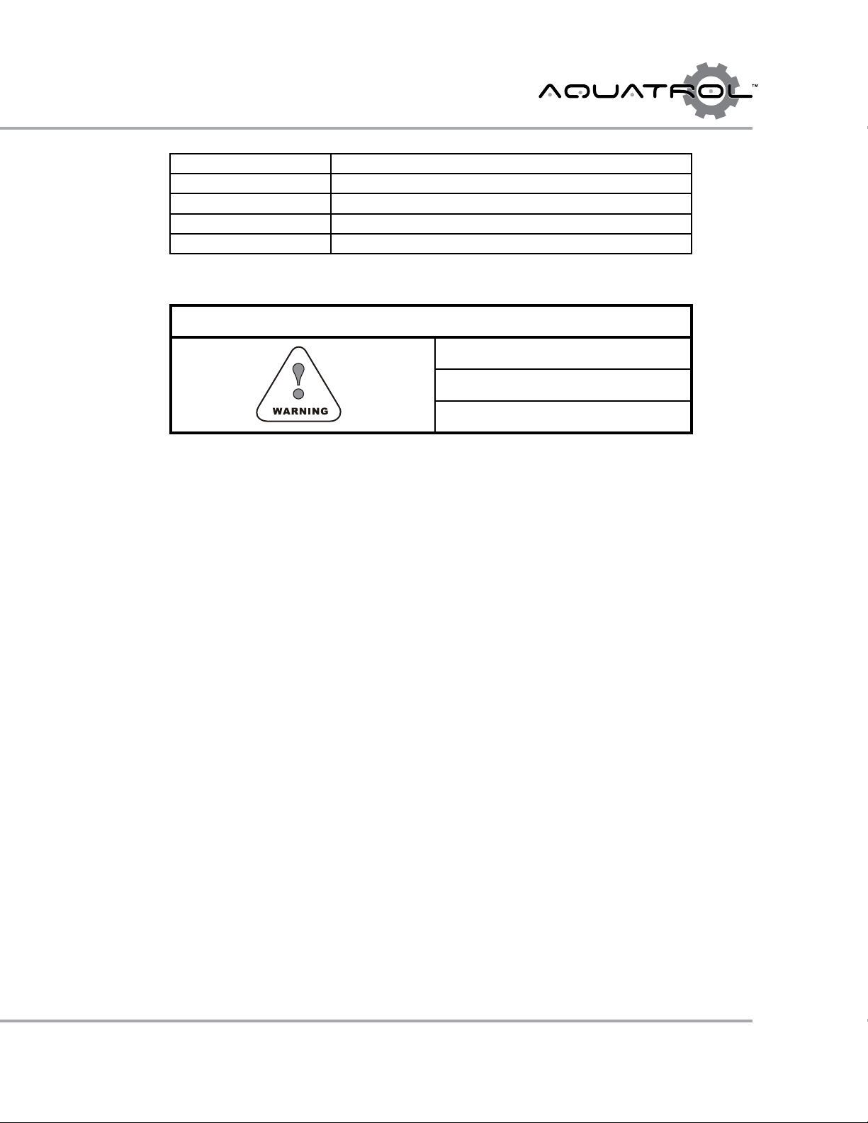
Rotate the skipper wheel until the number "1" is at the red pointer.
Set the days that regeneration is to occur by sliding tabs on the
skipper wheel outward to expose trip ngers.
Each tab is one day. Finger at red pointer is tonight.
Moving clockwise from the red pointer, extend or retract ngers to
obtain the desired regeneration schedule.
How To Set The Time Of Day:
Press and hold the white button in to disengage the drive gear.
Turn the large gear until the actual time of say is at the time of day
pointer.
Release the white button to again engage the drive gear.
How To Manually Regenerate Your Water Condi-
tioner At Any Time:
Turn the manual regeneration knob clockwise.
This slight movement of the manual regeneration knob engages
the program wheel and starts the regeneration program.
The black center knob will make one revolution in the following
approximately three hours and stop in the position shown in the
drawing.
Even though it takes three hours for this center knob to complete
one revolution, the regeneration cycle of your unit might be set
only one half of this time.
In any event, conditioned water may be drawn after rinse water
stops owing from the water conditioner drain line.
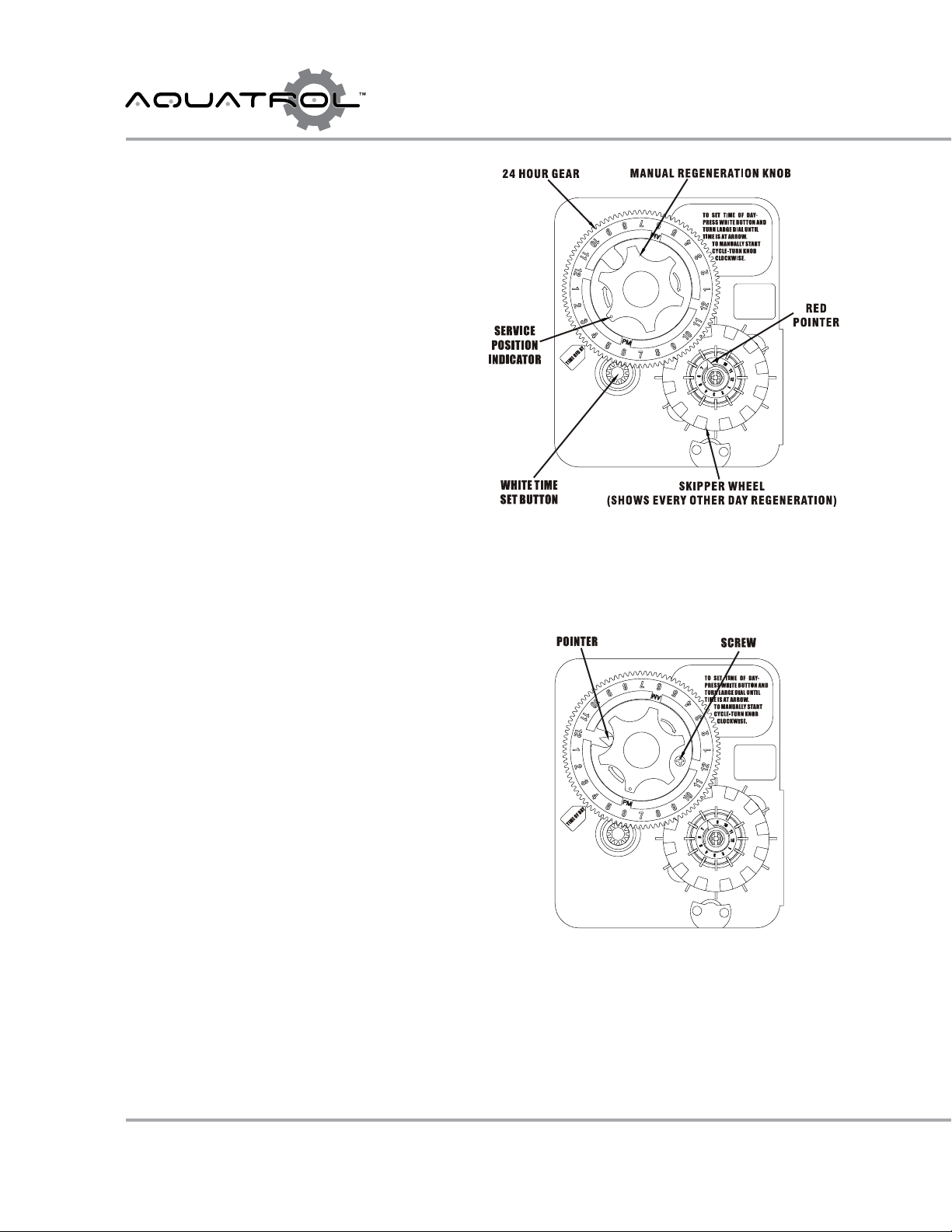
How To Adjust Regeneration Time:
1. Disconnect the power source.
2. Locate the three screws behind the manual regeneration knob
by pushing the white button in and rotating the 24 hour dial
until each screw appears in the cut out portion of the manual
regeneration knob.
3. Loosen each screw slightly to release the pressure on the time
plate from the 24 hour gear.
4. Locate the regeneration time pointer on the inside of the 24
hour dial in the cut out.
5. Turn the plate so the desired regeneration time aligns next to
the raised arrow.
6. Push the white button in and rotate the 24 hour dial. Tighten
each of the three screws.
7. Push the white button and locate the pointer one more time to
ensure the desired regeneration time is correct.
8. Reset the time of day and restore power to the unit.

Page 6
CONTROL VALVES
AQT-315 Timer Delay
Start-up Setting Procedures
Typical Programming Procedure
Calculate the gallon capacity of the system, subtract the necessary reserve requirement and set the gallons required by lifting the gallon
dial and rotating it so that the number of gallons required is aligned with the white dot on the program wheel gear. Release and check for
rm engagement with gear.
Note: To set meter capacity at initial start-up, either:
1. Rotate the manual regeneration knob one full revolution.
or
2. Rotate the program wheel manual clockwise and align white dot with capacity arrow.
This procedure must be followed any time the program wheel setting is changed.
How To Set The Time Of Day:
Press and hold the white button in to disengage the drive gear.
Turn the large gear until the actual time of say is opposite of the time of day pointer.
Release the white button to again engage the drive gear.
How To Manually Regenerate Your Water Conditioner At Any Time:
Turn the manual regeneration knob clockwise one "click".
This slight movement of the manual regeneration knob engages the program wheel and starts the regeneration program.
The black center knob will make one revolution in the following approximately three hours and stop in the position shown in the drawing.
Even though it takes three hours for this center knob to complete one revolution, the regeneration cycle of your unit might be set for only
on half of this time.
In any event, conditioned water may be drawn after rinse water stops owing from the water conditioner drain line.
Immediate Regeneration Times:
These timers do not have a 24 hour gear. Setting the gallons on the program wheel and manual regeneration procedure are the same as
previous instructions.
NOTE:
To set meter capacity
rotate manual knob
1-360º revolution to
set the gallons.

Page 7
CONTROL VALVES
How To Set The Regeneration Cycle Program:
The regeneration cycle program on your water conditioner has been factory preset, however, portions of the cycle or program may be
lengthened or shortened in time to suit local conditions.
Timer Setting Procedure:
How To Change The Length Of The Backwash Time:
The program wheel as shown in the drawing is in the service position. As you look at the numbered side of the program wheel, the group
of pins starting at zero determines the length of time your unit will backwash.
For example: If there are six pins in this section, the time of backwash will be 12 min. (2 min. per pin).To change the length of backwash
time, add or remove pins as required. The number of pins times two equals the backwash time in minutes.
How To Change The Length Of Brine And Rinse Time:
The group of holes between the last pin in the backwash section and the second group of pins determines the length of time that your
unit will brine and rinse (2 min. per hole).
To change the length of brine and rinse time, move the rapid rinse group of pins to give more or fewer holes in the brine and rinse section.
Number of holes times two equals brine and rinse time in minutes.
How To Change The Length Of Rapid Rinse:
The second group of pins on the program wheel determines the length of time that your water conditioner will rapid rinse (2 min. per pin)
To change the length of rell time, add or remove pins at the higher numbered end of this section as required. The number of pins times
two equals the rapid rinse time in minutes.
How To Change The Length Of Brine Tank Rell Time:
The second group of holes in the program wheel determines the length of time that your water conditioner will rell the brine tank (2 min.
per hole).
To change the length of rell time, move the two pins at the end of the second group of holes as required.
The regeneration cycle is complete when the outer microswitch is tripped by the two pin set at the end of the brine tank rell section.
The program wheel, however, will continue to rotate until the inner micro-switch drops into the notch on the program wheel.
Regeneration Cycle
Program Setting Procedures

Page 8
CONTROL VALVES
Water Conditioner
Flow Diagrams
Air Check
Brine Level
Salt Level
Brine Tank
Resin Tank
Inlet
Outlet
Drain
Inlet
Resin Level
1) Service Position
Hard water enters unit at valve inlet and ows down
through the mineral in the mineral tank. Conditioned water
enters center tube through the bottom distributor, then
ows up through the center tube, around the piston, and
out the outlet of the valve.
Air Check
Brine Level
Salt Level
Brine Tank
Resin Tank
Inlet
Outlet
Drain
Inlet
Resin Level
2) Backwash Position
Hard water enters unit at valve inlet and ows through
the piston and down the center tube, through the bottom
distributor and up through the mineral, around the piston
and out the drain line.

Page 9
CONTROL VALVES
Water Conditioner
Flow Diagrams
3) Brine Position
Hard water enters unit at valve inlet - ows up into injector
housing and down through nozzle and orice to draw brine
from the brine tank - brine ows down the center tube
through bottom of tank, up through the mineral to top of
tank, around the piston and out the drain line.
4) Slow Rinse Position
Hard water enters unit at valve inlet - ows up into injector
housing and down through nozzle and orice - around the
piston - down through center tube and bottom distributor
- ows up the mineral, around piston and out through the
drain line.
Air Check
Brine Level
Salt Level
Brine Tank
Resin Tank
Inlet
Outlet
Drain
Inlet
Resin Level
Air Check
Brine Level
Salt Level
Brine Tank
Resin Tank
Inlet
Outlet
Drain
Inlet
Resin Level
5) Rapid Rinse
Hard water ows directly from inlet down through the
mineral into the bottom distributor and up through the
center tube - around the piston and out the drain line.

Page 10
CONTROL VALVES
Water Conditioner
Flow Diagrams
6) Brine Tank Fill Position
Hard water enters unit at valve inlet -ows up through the
injector housing and through the brine valve to ll brine
tank.
Air Check
Brine Level
Salt Level
Brine Tank
Resin Tank
Inlet
Outlet
Drain
Inlet
Resin Level

Page 11
CONTROL VALVES
Dimensional
Drawings

Page 12
CONTROL VALVES
Body Valve
Assembly
1
2
3
4
5
6
7
8
9
10
11
12
13 14
No Hard Water Bypass Piston
Filter Valve Body

Page 13
CONTROL VALVES
Body Valve
Assembly Parts List
Item No. Quantity Part No. Description
1 1 A-60106-00 Piston HW, AQT-315, AQT-390 Upper
2 1 A-60113-01 Piston NHW, AQT-315, AQT-390 Upper
3 1 A-60131 Seals & Spacers, AQT-315, AQT-390 Upper
4 2 A-02057F Screw, Body
5 1 A-15114 Body, Valve, AQT-315
6 1 A-00108F Straight Pin
7 1 A-15112 Seal, Valve Body-Adapter
8 1 A-15117-01 Adapter
9 1 A-13575 O-ring
10 1 A-15247 O-ring
11 4 A-12473 Screw, Plug, Injector
12 2 A-16341-02 Plug, Injector, 180
13 2 A-15246 O-ring, Plug, Injector
14 2 A-31509F Screw, Male Plug

Page 14
CONTROL VALVES
A-60711
DLFC, 2” NPT
DLFC Buttons
(4 X DLFC)
DLFC
Assembly

Page 15
CONTROL VALVES
* DLFC Button / Washer Options (x 4, can be mixed)
A-17942 DLFC Washer, 5 gpm
A-17943 DLFC Washer Flow 8 gpm
A-17944 DLFC Washer Flow 9 gpm
A-16529 DLFC Washer Flow 10 gpm
A-16735 DLFC Washer Flow 12 gpm
A-16736 DLFC Washer Flow 15 gpm
A-16528 DLFC Washer Flow 20 pm
A-16737 DLFC Washer Flow 25 gpm
DLFC
Assembly Parts List

Page 16
CONTROL VALVES
Control Drive
Assembly
3
74
8910 11 12
13
14
15
16
17
18
19
20
21
25
26
9
27
23
28
30
31
32 33 34
29
35
36
37
1
6
23 22
24
2
4
5
2

Page 17
CONTROL VALVES
Item No. Quantity Part No. Description
1 1 A-17470 Cable Guide, Meter
2 1 A-17470-00 Screw Cap
3 2 A-16346 Nut, Timer
4 2 A-11225 Screw, Timer
5* 1 Timer, Mechanical
6 3 A-10016S Screw, Motor Mounting
7 3 A-15120-01 Motor, Bracket
8 2 A-11224 Hex Bolt, Motor Bracket
9 2 A-16052 Bushing
10 1 A-11898 Retainer
11 1 A-16047 Connecting Link
12 1 A-11709 Pin-drive Link
13 1 A-11774 Retaining Ring
14 1 A-16050 Retaining Ring
15 1 A-16046 Drive Gear, Kit (includes #10 - #16), 315/390
16 1 A-16048 Drive Bearing
17 1 A-60240 Valve Cover
18 1 A-60240 Screw, Cover
19 1 A-60240 Transparent Panel
20 1 A-60240 Washer
21 1 A-60240 Screw
22 1 A-16052-1 Bushing, Cam
23 2 A-16051 Retaining Ring
24 1 A-16494-03 Cam
25 4 A-10231 Hex Bolt, Bracket, Brine Valve
26 1 A-16053 Bracket, Brine Valve
27 1 A-16059 Washer, SS
28 3 A-17797 Bracket, Switch Mounting 315/390
29 1 A-11381 Roll Pin
30 3 A-10302 Insulator, Switch
31 3 A-10218 Switch
32 2 A-40080 Screw, Switch
33 1 A-30018F Motor 24V, AQT-275, 285, 290 Up, 315, 390 Up & Low
34 1 A-16045-3G Drive Pinion, Motor 3rd Gen.
35 1 A-19304 Back Plate
36 4 A-11235 Nut
37 1 A-07190F Transformer, 24V, 60Hz, for Mechanical and NX
Control Drive
Assembly Parts List

Page 18
CONTROL VALVES
180 Brine System
Assembly
2
6.2
5
3
8
7
6.1
5
4
3
1
9
10
11
Injector*
# 6.1
# 6.2
12
13
14
15
16
PN 1 - 14 -------- A-60277 --- Brine Valve, Short Stem, Less BLFC, 1”for AQT-315 & AQT-390
PN 10 - 14 ------ A-60036 --- Inyector Body, 1”for AQT-315 & AQT-390

Page 19
CONTROL VALVES
Item No. Quantity Part No. Description
1 1 A-18703 Brine Tube
2 2 A-18702 Tube Fitting
3 6 A-12473 Screw
4 1 A-16341-01 Cap, Injector, BV-180
5 2 A-15246 O-Ring, Cap, Injector, BV-180
6.1* 1 Injector Nozzle
6.2* 1 Injector Throat
7 1 A-16340 Injector Body
8 2 A-12473 Screw
9 1 A-19054 O-Ring
10 1 A-16497-01 Brine Stem Assembly
11 1 A-18713 Brine Valve Body, BV-180
12 1 A-11772 Spring, BV-180
13 1 A-11774 Retaining Ring
14 1 A-16498-01 Stem Guide Assembly
15** 1 BLFC, Button
16 1 A-60710 BLFC, Brine Fitting, BV-180
180 Brine System
Assembly Parts List
* BLFC Button / Washer Options
A-17942 BLFC Washer, 5 gpm
A-17943 BLFC Washer, 8 gpm
A-17944 BLFC Washer, 9 gpm
A-16529 BLFC Washer, 10 gpm
A-16735 BLFC Washer, 12 gpm
A-16736 BLFC Washer, 15 gpm
A-16528 BLFC Washer, 20 gpm
A-16737 BLFC Washer, 25 gpm

Page 20
CONTROL VALVES
Troubleshooting
Problems, Cause & Corrections
Problem Cause Correction
1) Softener fails to regenerate. A) Electrical service to unit has been
interrupted.
A) Assure permanent electrical service
(check fuse, plug, pull chain or switch).
B) Timer is defective. B) Replace timer.
C) Power failure. C) Reset time of day.
2) Hard water. A) By-pass valve is open. A) Close by-pass valve.
B) No salt in brine tank. B) Add salt to brine tank and maintain salt
level above water level.
C) Injector screen plugged. C) Clean injector screen.
D) Insucient water owing into brine
tank.
D) Check brine tank ll time and clean
brine line ow control if plugged.
E) Hot water tank hardness. E) Repeated ushing of the hot water tanks
required.
F) Leak at distributor tube. F) Make sure distributor tube is not
cracked. Check O-ring and tube pilot.
G) Internal Valve Leak. G) Replace seals and spacers and/or piston.
H) Service Adapter did not return to
service.
H) Check drive motor and switch.
3) Unit used too much salt. A) Improper salt setting. A) Check salt usage and salt setting.
B) Excessive water in brine tank. B) See problem No. 7.
4) Loss of water pressure. A) Iron buildup in line to water conditioner. A) Clean line to water.
B) Iron buildup in water conditioner. B) Clean control and add mineral cleaner
to mineral bed. Increase frequency of
regeneration.
C) Inlet of control plugged due to foreign
material broken loose from pipes by recent
work done on plumbing system.
C) Remove piston and clean control.
5) Loss of mineral through drain line. A) Air in water system. B) Assure that well system has proper
air eliminator control. Check for dry well
conditions.
B) improper size drain line ow control. B) Check for proper drain rate.
6) Iron in conditioned water. A) Fouled mineral bed. A) Check backwash, brine draw and
brine tank ll. Increase frequency of
regeneration. Increase backwash time.
7) Excessive water in brine tank. A) Plugged drain line ow control. A) Clean ow control.
B) Plugged injector system. B) Clean injector and screen.
C) Timer not cycling. C) Replace timer.
D) Foreign material in brine valve. D) Replace brine valve seat and clean valve.
E) Foreign material in brine line ow
control.
E) Clean brine line ow control.
Table of contents
Other AQUATROL Control Unit manuals

AQUATROL
AQUATROL AQT-275 User manual

AQUATROL
AQUATROL POWERFLO Series Owner's manual

AQUATROL
AQUATROL POWERFLO Series User manual

AQUATROL
AQUATROL AQT-MSV-1 Quick start guide

AQUATROL
AQUATROL 69 Manual

AQUATROL
AQUATROL AQT-56ST User manual

AQUATROL
AQUATROL POWERFLO AQT-290 User manual

AQUATROL
AQUATROL 88 Manual

AQUATROL
AQUATROL POWERFLO AQT-285 User manual
Popular Control Unit manuals by other brands

Siemens
Siemens HiPath optiPoint 410 Developer's guide

oventrop
oventrop Regufloor HW Installation and operating instructions for the specialised installer

RF-Star
RF-Star SimpleLink RF-BM-2652P3 manual

Tyco
Tyco DV-5A manual

Parker Pneumatic
Parker Pneumatic PVLC10 installation instructions

Stone
Stone STWI056WT-01 Equipment manual