Aquion ProSystems NRV 1044 User manual

Part No.: 37205
Rev: C 02/03/16
The NRV Whole House Carbon Filter is tested and certified by WQA to NSF/ANSI 61 for
material safety requirements only.
The NRV Whole House Carbon Filter is tested and certified by WQA to NSF/ANSI 372 for
low lead compliance.
ProSystems, a Division of Aquion, Inc.
101 S. Gary Avenue
Roselle, Illinois 60172
1.800.811.3489
www.prosystemswater.com
This product is manufactured in an ISO 9001:2008 certified facility.
™
NRV WHOLE HOUSE FILTER

TABLE OF CONTENTS
2
System Information ......................................................................................................................................3
Pre-Installation Instructions ..........................................................................................................................3
Installation Instructions ..............................................................................................................................4-5
Exploded Views and Parts Lists ................................................................................................................6-7
Troubleshooting Guide..................................................................................................................................8
Warranty Information ....................................................................................................................................9

You now own the finest Water Treatment System available to homeowners. To enjoy the maximum
benefits of this system, please read the contents of this Owners Manual.
SYSTEM INFORMATION
WATER PRESSURE
A minimum of 20 pounds of water pressure is required for proper operation of the system. The
operating pressure range is 20 psi - 120 psi (138 kPa - 828 kPa).
BYPASS VALVE
The bypass valve enables the customer to bypass the system in situations of: emergency leaks in the
equipment, service calls and/or outdoor water use.
OPERATING TEMPERATURE RANGE
Range: 40° F - 100° F (4.4° C - 38° C)
ENVIRONMENTAL REQUIREMENTS
The water filter cannot be exposed to outdoor elements, such as direct sunlight or atmospheric precip-
itation. The system may be installed in a covered, open-air structure such as a carport, residential or
commercial building.
OPERATIONAL SPECIFICATIONS
The carbon bed will eventually become exhausted and will need to be replaced.
Carbon is available in cubic foot bags as part number 38850.
KDF is available in 1/10 cubic foot bags as part number 19099.
PRE-INSTALLATION INSTRUCTIONS
•Do not install this system where water is microbiologically unsafe or of unknown quality without
adequate disinfection before or after the system.CARBON/KDF models are intended for the removal
of sulfate reducing bacteria (SRB).
•This system must be installed in an area that is not affected by extreme heat, cold or the elements.
The selected installation area must be adequate for easy service of all parts.
•This system must be installed in accordance with all applicable state and local laws and regulations.
•This system is designed to treat cold water only and can be installed on any cold water supply.
3
SYSTEM
(PART NUMBER)
CARBON AMOUNT
(CU. FT)
KDF AMOUNT
(CU. FT)
SERVICE FLOW
RATE (gal/min)
PSI DROP AT
SERVICE FLOW
RATE
NRV1044 CARBON (35463) 1.4 08.0 3
NRV1054 CARBON (35464) 1.85 010.0 5
NRV1044 CARBON/KDF (35479) 1.3 0.1 8.0 3
NRV1054 CARBON/KDF (35480) 1.75 0.1 10.0 5

INSTALLATION INSTRUCTIONS
1. SAFETY PRECAUTIONS
• To prevent accident or injury, do not hoist the unit over your shoulder. Use a hand truck to transport
the unit. Note: Do not lay the unit on its side during transportation and/or installation.
• Wear safety glasses and work gloves during installation and service.
2. TEST THE RAW WATER
•If source water contains iron, manganese or hydrogen sulfide, a separate iron removal system is
suggested to be installed prior to the system; consult your local dealer. CARBON/ KDF models are
intended for use when sulfate reducing bacteria (SRB) is present.
3. CHECK WATER PRESSURE
•Use a pressure gauge to confirm that the water pressure does not exceed 120 psi. If the water
pressure does exceed this limit, install a pressure regulator on the inlet pipe of the unit. The minimum
pressure for a filter is 20 psi. 60 psi is the optimum operating pressure.
4. LOCATE A SITE FOR THE UNIT
•Locate the system near the main water source. In most applications, bypass any outside faucets.
•Place the unit in the desired location. The location must have a level, smooth surface.
•If the system is located outdoors, protect the unit from direct sunlight. (Direct sunlight can damage
the fiberglass and other system components.) If necessary, build a box or shed. Note: The system can
only be installed outdoors in climates that do not reach freezing levels.
5. TURN OFF THE WATER AND DRAIN THE PLUMBING
• Turn off the water at the meter or the pressure tank.
•Drain all the pipes. Do not sweat the pipes with water in them; steam will damage plastic parts in the
valve.
• To drain the plumbing system, open all the faucets in the house and flush the toilets. This procedure
will allow air to enter the plumbing system. The water will drain out of the lowest faucet or outlet.
6. BYPASS THE OUTSIDE FAUCETS
•When possible it is best to bypass the outside faucets. However in some cases the outside faucets
can not be accessed. In this situation the bypass valve should be used whenever watering outside
for extended periods of time. If the installation is outside or in a garage a faucet can be installed on
the inlet water side to provide an option for untreated water.
7. CONNECT THE PLUMBING TO THE BYPASS VALVE
•Do not point the soldering torch directly at the system. The thermo-plastic material will last a lifetime,
4
OUTLET
INLET
Bypass couplers
Bypass valve
Yoke with 1" plumbing

within normal operating temperatures, but will melt in a torch flame.
• To prevent hot water from backing up into the conditioner, avoid short connections of pipe between
the conditioner and the hot water heater. If you can’t avoid a short connection, move the equipment
to another location. As a last resort, install a check valve. If the check valve causes “water hammer”,
install a water hammer suppressor.
•Connect the raw water pipe to the INLET pipe connection of the bypass valve. When looking from the
front of the unit, the inlet is the pipe connection on the RIGHT side of the valve.
•Connect the treated water pipe to the OUTLET pipe connection of the bypass valve. When looking
from the front of the unit, the outlet is the pipe connection on the LEFTside of the valve.
8. TURN ON THE WATER AND TEST FOR LEAKS AND FLUSH THE PLUMBING
•Before turning the water back on, place the system in the bypass position, then close all of the faucets
except one cold water tap from a bath tub.
• Turn the water on slowly and allow the water to flow out the bath tub for several minutes to remove
any dirt, solder, glue, etc. from the plumbing system.
•Once the water runs clear, turn the bypass valve handles to the service position and allow the water
to fill the system. It is common for water to show some color ( grey or brown) for a few minutes. Allow
the water to run for 20 minutes or until 100 gallons have passed through the system. Once the water
runs clear shut off the bath tub.
•The system will now pressurize, allowing you to check for any leaks.
• To flush any remaining untreated water from the hot water heater, run hot water in the bathtub until
cold; close the faucet.
The installation is complete and the system is ready for use.
5

6
ITEM QUANTITY PART NUMBER DESCRIPTION
1 1
38256 NRV 1044 CARBON; 1044 CARBON/KDF
38257 NRV 1054 CARBON; 1054 CARBON/KDF
TANK WITH BASE
2 1 RISER PIPE ASSEMBLY
3 1 19567 DISTRIBUTOR ADAPTER KIT
41 19574 HEAD 2in CENTER
6 2 19593 COUPLER ADAPTER
72 17961 119 O-RING
8 2 19575 CLIP
9 2 17966 SCREW SLOT IND HEX 8-18 X 5/8
10 1 17557 BYPASS VALVE
11 1 17862 PLUMBING YOKE 1IN SWEAT
NRV 1044 CARBON
NRV 1054 CARBON
PARTS LIST & EXPLODED VIEWS FOR:
NRV 1044 CARBON; 1044 CARBON/KDF
27
10
3
4
58
9
NRV 1054 CARBON; 1054 CARBON/KDF
18623
18851
11
6
1
52 70273 O-RING 29.5mm ID
2 BOXES 38850 CARBON, 1 CU. FT. BOX
QUANTITY PART NUMBER DESCRIPTION
1 BAG 17732 GRAVEL UNDERBEDDING, 50 LB. BAG
REPLACEMENT MEDIA
*NRV 1044 CARBON USES 1.40 CU.FT. OF CARBON AND 15 LBS OF GRAVEL UNDERBEDDING.
NRV 1054 CARBON USES 1.85 CU.FT. OF CARBON AND 15 LBS OF GRAVEL UNDERBEDDING.
NRV 1044 CARBON/KDF USES 1.30 CU.FT. OF CARBON, 0.1 CU.FT. OF KDF, AND 15 LBS OF GRAVEL UNDERBEDDING.
NRV 1054 CARBON/KDF USES 1.75 CU.FT. OF CARBON, 0.1 CU.FT. OF KDF, AND 15 LBS OF GRAVEL UNDERBEDDING.
NRV 1044 CARBON/KDF
NRV 1054 CARBON/KDF
1 BAG 19099 KDF, 0.1 CU. FT. BAG

7
ALL DIMENSION ARE IN INCHES - TOLERANCE +/- 0.25
AB
2.0"
C
TANK SIZE DIMENSION A DIMENSION B DIMENSION C
10 x 44
10 x 54
46 1
4"
56"
47 3
4"
57 1
2" 10 1
2"
10 1
2"
SYSTEM
NUMBER
35463 / 35479
35464 / 35480

SYMPTOM CAUSE SOLUTION
1. Poor water quality 1. Bypass valve is in bypass position 1. Close the bypass valve.
2. Loss of filter media 2. Refer to Symptom 2.
3. Capacity of filter media is exhausted 3. Replace the filter bed.
4. Leak at the rise tube 4. Verify that the riser tube is seated correctly
and is not cracked.
2. Loss of filter media 1. The lower distributor is damaged 1. Replace the distributor, Flush pipes of filter
media, add replacement filter media lost from
system.
2. INLET and OUTLET water connections are
reversed
2. Disconnect and reconnect INLET and OUTLET
in correct orientation. Flush pipes of filter media;
add replacement filter media lost from system.
3. Loss of water pressure 1. Low pressure to the system 1. Bypass the system to confirm the problem
•If the problem still exists after bypass, it is
not related to the filter. Have your water
distribution system checked.
•If the problem is resolved after bypass,
check the following causes:
2. Mineral or iron build up in the filter tank. 2. Replace the filter bed
3. Plugged lower distributor or riser pipe 3. Remove the debris from the distributor and
riser pipe
4. Crushed lower distributor 4. Replace the riser pipe assembly
8
If the troubleshooting guide did not resolve the unit’s symptoms, please contact your local Dealer for service.
TROUBLESHOOTING GUIDE

Water Treatment Systems Limited Product Warranty
STATEMENT OF LIMITED PRODUCT WARRANTY
Limited Warranty Coverage
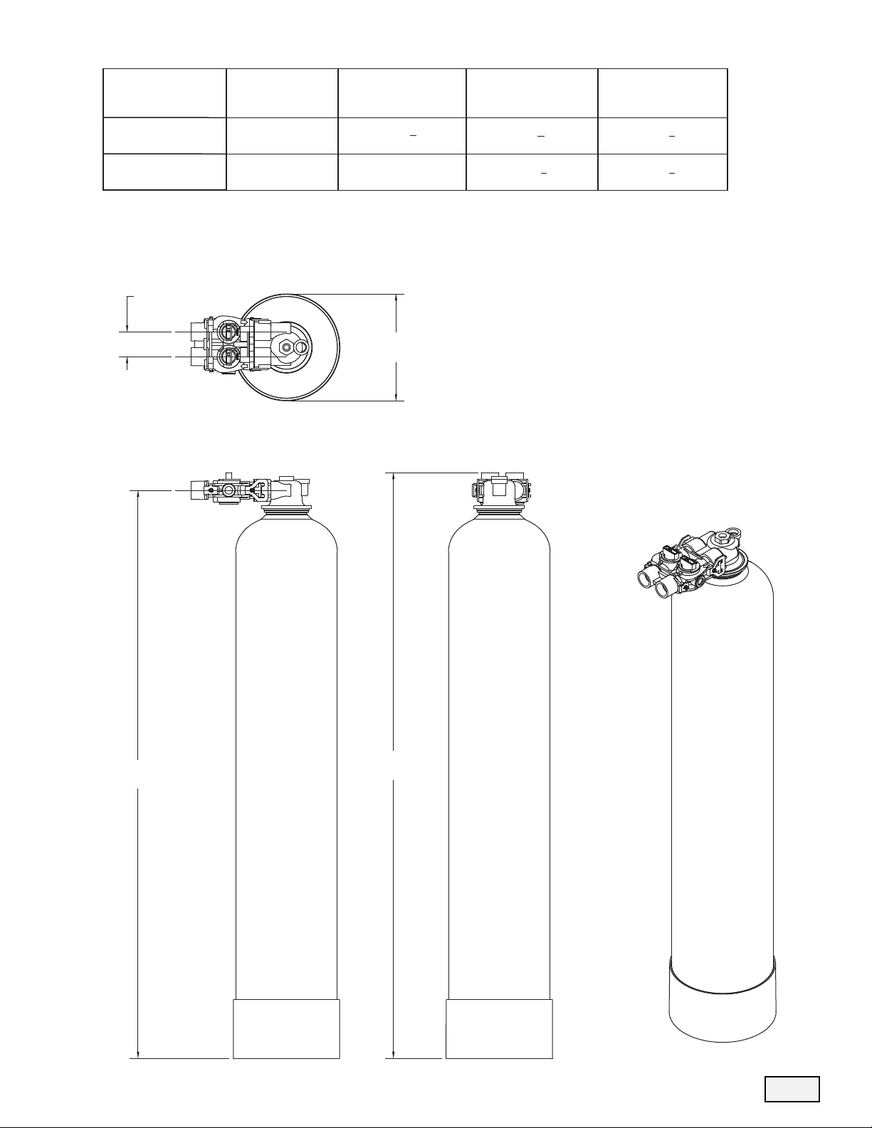
For ProSystems NRVWhole House Filters. The products are warranted to be free from defects in material and/or workmanship
under normal use and service for the following:
The Resin/Media tank, will carry a ten (10) year warranty from the date of shipment. The valve body will also carry a (10) year war-
ranty. The Media will carry a three (3) year warranty on municipal water, and a one (1) year warranty on well water. Any replace-
ment product(s) provided by ProSystems Water Treatment Systems pursuant to this Limited Warranty will be warranted only for the
remainder of the original limited warranty period or thirty (30) days from the date of shipment, whichever is longer.
The following are specifically excluded from the Limited Warranty coverage provided herein:
• Defects or problems not reported to ProSystems Water Treatment Systems during the applicable warranty period.
• Any products manufactured by other companies that are used in connection with ProSystems Water Treatment Systems product.
• Problems resulting from the alteration, modification, misuse, abuse, neglect, improper care, maintenance or negligent use,including
but not limited to unprotected outdoor installation of any ProSystems Water Treatment Systems product.
Procedure for Obtaining Limited Warranty Coverage
In order to obtain the benefits of this Limited Warranty, defective part(s) and/or product(s) must be returned to ProSystems Water
Treatment Systems as soon as possible after discovery of the defect, but not later than the expiration date of the warranty period
provided in this Limited Warranty. The Technical Service Department at ProSystems Water Treatment Systems will issue a Warranty
Return Authorization (WRA) number for the defective part(s) or product(s) which must be clearly marked on the outside of the pack-
age being returned. Packages must be shipped freight prepaid, along with a letter stating the part number, serial number, if any, the
date of purchase of the item which is claimed to be defective and a brief description of the problem detected. ProSystems Water
Treatment Systems is not responsible under this Limited Warranty for any cost incurred for shipping or transportation in connection
with the return of the part(s) or product(s).
Repair or Replacement
Upon receipt of the product and warranty claim, ProSystems Water Treatment Systems will verify the reported failure and determine
if the part(s) or product(s) is/are covered by this Limited Warranty. If this Limited Warranty applies, ProSystems Water Treatment
Systems will, at its option, repair or replace the part(s) or product(s).
No Liability for Consequential Damages
Unless otherwise required by applicable law, ProSystems Water Treatment Systems shall not be liable for any damages whatsoever
(including without limitation, loss time, inconvenience, expenses such as telephone calls, labor or material charges incurred in con-
nection with the removal or replacement of the part(s) or product(s), special, incidental, consequential, or indirect damages for per-
sonal injury, loss of business profits, business interruption, loss of business information, or any other pecuniary loss) arising out of
the use of or inability to use the defective part(s) or product(s), even if ProSystems Water Treatment Systems has been advised of
the possibility of such damages. ProSystems Water Treatment Systems entire liability under any provision of this Limited Warranty
shall be limited to the amount actually paid for the part(s) or product(s).
NOTE: Because some states/jurisdictions do not allow the exclusion or limitation of incidental or consequential damages, the above
limitation or exclusion may not apply.
No Other Warranties:
ProSystems Water Treatment Systems specifically disclaims all other warranties, either express or implied, including, but not limited
to implied warranties of merchantability and fitness for a particular purpose, with regard to the part(s), product(s) and/or any accom-
panying written materials. This limited warranty gives you specific legal rights. You may have other rights that vary from state/juris-
diction to state/jurisdiction.
Order Department Direct Line: 847-758-5973 • Fax: 847-437-5539
Toll-free: 800-811-3489
9

10
NOTES

11
NOTES

ProSystems, a Division of Aquion, Inc.
101S. Gary Avenue •Roselle•Illinois 60172
800-811-3489
©2016 Aquion, Inc.
This manual suits for next models
1
Table of contents
Other Aquion Water Dispenser manuals
Popular Water Dispenser manuals by other brands

Marco
Marco 1001866US quick start guide

MTN Products
MTN Products AquaHostess quick start guide

Brandt
Brandt BFC2302NW instruction manual

Elkay
Elkay DSBWCB5G Installation, care & use manual

Quality Water Treatment
Quality Water Treatment SoftPro Natural Soft Series Installation, operation and maintenance manual

Whirlpool
Whirlpool WHES40 Installation and operation manual