Aquion Oxydizer User manual

© 2012 Aquion, Inc. TM-EN-Oxydizer-Rev2012.08
T
TE
EC
CH
HN
NI
IC
CA
AL
L
M
MA
AN
NU
UA
AL
L
Fe, Mn, H2S
WATER FILTER

TABLE OF CONTENT & INSTALLATION RECORD
Page 2
Table of content...................................................................................................................Page 2
Warning & Safety instructions.............................................................................................Page 3
Operating conditions & Requirements................................................................................Page 4
Installation ...........................................................................................................................Page 5
Start-up................................................................................................................................Page 6
Electronic control panel.......................................................................................................Page 7
Maintenance........................................................................................................................Page 9
Hydraulic flow diagrams - O2xydizer....................................................................................Page 10
Hydraulic flow diagrams - O2xydizerPRO...............................................................................Page 11
Troubleshooting...................................................................................................................Page 12
Electrical wiring diagrams....................................................................................................Page 13
Default parameter settings..................................................................................................Page 14
Exploded view - System.......................................................................................................Page 16
Exploded view - Timer head ................................................................................................Page 18
Exploded view - Valve body O2xydizer ................................................................................Page 20
Exploded view - Valve body O2xydizerPRO............................................................................Page 22
Technical Specifications.......................................................................................................Page 24
WARNING & SAFETY INSTRUCTIONS
Page 3
Before you begin the installation of the water filter, we advise you
read and carefully follow the instructions contained in this manual. It
contains important information about safety, installation, use and
maintenance of the product. The actual system that you have
received, may differ from the pictures/illustrations/descriptions in
this Technical Manual.
Failure to follow the instructions could cause personal injury or
damage to the appliance or property. Only when installed,
commissioned and serviced correctly, the water filter will offer you
many years of trouble-free operation.
The water filter is intended to 'filter' the water, meaning it will
remove specific undesired substances; it will not necessarily remove
other contaminants present in the water. The water filter will not
purify polluted water or make it safe to drink!
Installation of the water filter should only be undertaken by a
competent person, aware of the local codes in force. All plumbing
and electrical connections must be done in accordance with local
codes.
Before setting up the water filter, make sure to check it for any
externally visible damage; do not install or use when damaged.
Use a hand truck to transport the water filter. To prevent accident or
injury, do not hoist the water filter over your shoulder. Do not lay the
water filter on its side.
Keep these Instructions in a safe place and ensure that new users are
familiar with the content.
The water filter is designed and manufactured in accordance with
current safety requirements and regulations. Incorrect repairs can
result in unforeseen danger for the user, for which the manufacturer
cannot be held responsible. Therefore repairs should only be
undertaken by a competent technician, familiar and trained for this
product.
In respect of the environment, this water filter should be disposed of
in accordance with Waste Electrical and Electronic Equipment
requirements. Refer to national/local laws and codes for correct
recycling of this water filter.
OPERATING CONDITIONS & REQUIREMENTS
Page 4
APPLICATION LIMITATIONS:
Dissolved Oxygen (D.O.):
O2xydizer: min. 15% of Iron + Manganese content
O2xydizerPRO: N/A
pH: for Iron removal: 6,8 - 9,0
for Manganese removal: 8,0 - 9,0
for Iron & Manganese removal: 8,0 - 8,5
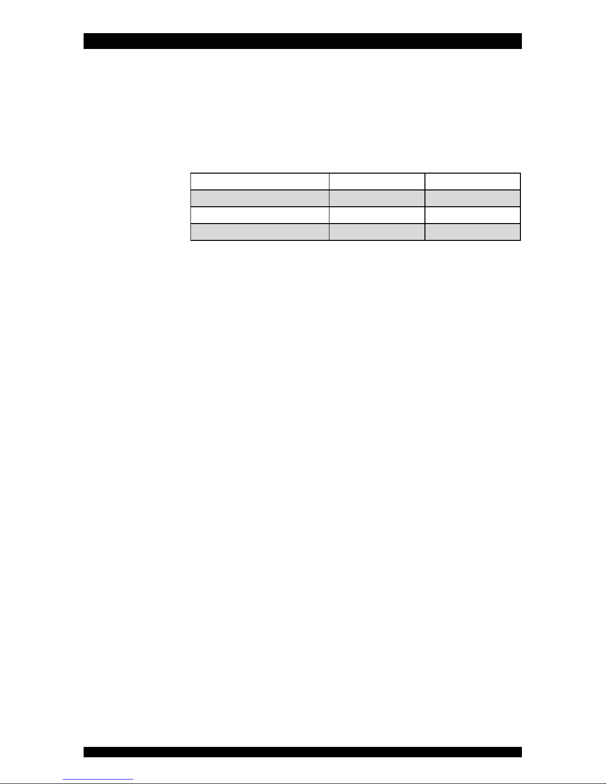
maximum contaminant content:
O2xydizer
O2xydizerPRO
Iron (Fe2+)
3 mg/L (1)
15 mg/L
Manganese (Mn2+)
2 mg/L (1)
2 mg/L
Hydrogen Sulfide (H2S)
0,1 mg/L (2)
5 mg/L
(1) largely depends on the D.O. content.
(2) max. level recommended by WHO.
organic matter: max. 4,0 mg/L; higher level may hinder the correct
operation of the system.
chlorine: max. 1,0 mg/L
iron bacteria: if iron bacteria are present, frequent service may be
necessary, while the life of the system may be limited; by properly
controlling the iron bacteria with chlorine or another approved method of
bacterial reduction, the system will function properly.
OPERATING PRESSURE: min. 1,4 / max. 8,3 bar
this system is configured to perform optimally at an operating pressure of
3 bar (±½ bar); in case of a higher operating pressure the performance
may be affected negatively!
if installed on a well, verify that the well pump is powerful enough to
provide sufficient flow rate for the regeneration.
check water pressure regularly.
install a pressure reducer ahead of the water filter if necessary.
OPERATING TEMPERATURE: min. 4 / max. 38 °C
do not install the water filter in an environment where high ambient
temperatures (e.g. unvented boiler house) or freezing temperatures can
occur.
the water filter cannot be exposed to outdoor elements, such as direct
sunlight or atmospheric precipitation.
do not install the water filter too close to a water heater; keep at least 3
m of piping between the outlet of the water filter and the inlet of the
water heater; water heaters can sometimes transmit heat back down the
cold pipe into the control valve; always install a check valve at the outlet
of the water filter.
ELECTRICAL CONNECTION: 230V-50Hz
this water filter only works on 24VAC; it is equipped with a 230/24V-50Hz
transformer; always use it in combination with the supplied transformer.
make sure to plug the transformer into a power outlet, which is installed
in a dry location, with the proper rating and over-current protection.
INSTALLATION
Page 5
INLET & OUTLET
Check the water pressure at the place of installation
of the water filter; it should never exceed 8,3 bar.
We strongly recommend the use of flexible hoses to
connect the water filter to the water distribution system;
use hoses with a large diameter in order to limit the
pressure loss.
If the water filter is not equipped with the factory
bypass (optional), we strongly recommend to install a 3-
valve bypass system (not included with this product!) to
isolate the water filter from the water distribution system
in case of repairs. It allows to turn off the water to the
water filter, while maintaining (untreated) water supply
to the user.
O2xydizerPRO only: to prevent air from escaping from
the compressed air chamber, make sure the inlet line runs
vertically upwards into the water filter. If this is not
possible, install a check valve in the inlet line.
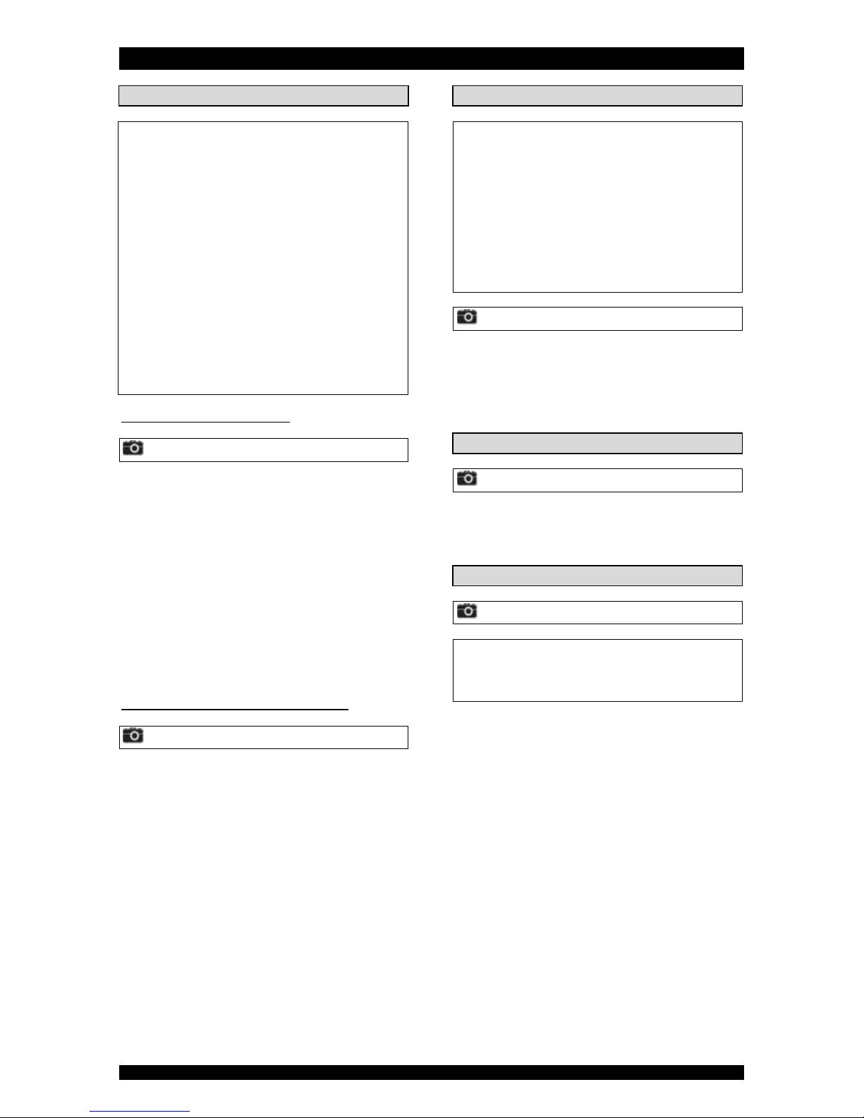
WITH FACTORY BYPASS (optional)
Picture 1
= mains water supply (untreated water)
= inlet of water filter (untreated water)
= outlet of water filter (treated water)
= house/application (treated water)
1. Screw the factory bypass onto the in/out ports on the
control valve (&); make sure to install the gasket
seals. Tighten the nuts firmly by hand.
2. Screw the connection kit with nuts onto the factory
bypass (&); make sure to install the gasket seals.
Tighten the nuts firmly by hand.
3. Connect the mains water supply to the nipple on the
inlet port of the factory bypass ().
4. Connect the house/application to the nipple on the
outlet port of the factory bypass ().
WITH 3-VALVE BYPASS SYSTEM (not included)
Picture 2
= mains water supply (untreated water)
= inlet of water filter (untreated water)
= outlet of water filter (treated water)
= house/application (treated water)
1. Install the 3-valve bypass system.
2. Screw the connection kit with nuts onto the in/out
ports on the control valve (&); make sure to install
the gasket seals. Tighten the nuts firmly by hand.
3. Connect the 3-valve bypass system to the nipples on
the in () and out () port of the control valve.
4. Connect the mains water supply to the inlet of the 3-
valve bypass system ().
5. Connect the house/application to the outlet of the 3-
valve bypass system ().
DRAIN
We recommend the use of a stand pipe with air trap.
To prevent backflow from the sewerage system into
the water filter, always make sure to have an air gap
between the end of the drain hose and the sewerage
system itself; as a rule of thumb, the air gap should be
minimum 2x the diameter of the drain hose.
Lay-out the drain hose in such a way that pressure
loss is minimized; avoid kinks and unnecessary elevations.
Make sure that the sewerage system is suitable for
the rinse water flow rate of the water filter.
Picture 3
1. Connect a 13 mm hose to the drain connection of the
control valve (); secure it by means of a clamp.
2. Run the drain hose to the sewerage system and
connect it to the stand pipe assuring sufficient air gap.
This drain line operates under pressure, so it may be
installed higher than the water filter.
ELECTRICAL
Picture 4
1. Plug the transformer into an electrical outlet.
2. Plug the transformers output lead into the socket on
the control valves power cord; secure it by means of
the TwistLock clamp.
AIR INJECTION SYSTEM (O2xydizerPRO only)
Picture 5
Make sure the air injection system is installed in
vertical position, with the check valve and air intake filter
screen pointing upwards. Rotate it to this position if
necessary.

START-UP
Page 6
PRESSURIZING
1. Make sure the bypass system is in 'bypass' position.
2. Make sure the electronic controller of the water filter
is in service mode.
3. Open the mains water supply.
4. Open a cold treated water faucet nearby the water
filter and let the water run for a few minutes until all
air is purged and all foreign material that may have
resulted from the installation is washed out; close the
tap.
5. Gently pressurize the water filter, by putting it into
service:
factory bypass:
1. open the 'outlet' valve;
2. slowly open the 'inlet' valve.
3-valve bypass:
1. close the 'bypass' valve;
2. open the 'outlet' valve;
3. slowly open the 'inlet' valve.
6. After 2-3 minutes, open a cold treated water faucet
nearby the water filter and let the water run until all
air is purged from the installation and the filter
medium is properly rinsed; it is normal for the rinse
water to show some discoloration; let the water run
until the rinse water is clear; close the tap.
7. Check the water filter and all hydraulic connections for
leaks.
O2xydizerPRO only: during the passage through the
compressed air chamber, the treated water will get
highly oxygenated. As a consequence it may become
slightly non-transparent (milky appearance) when it flows
from the tap into a glass. This is totally harmless for the
quality of the treated water and will disappear rapidly if
the water is left standing for a moment!
ELECTRONIC CONTROL PANEL
8. Program the electronic controller.
PERFORM REGENERATION
We strongly recommend to postpone the execution of
this 'start-up' regeneration by 24 hours. The filter
medium needs sufficient time to absorb water and reach
its normal service weight. If the regeneration is
performed too soon, the filter medium may be pushed
against the top distributor during the backwash cycle,
possibly resulting in loss of filter medium or damage to
the top distributor.
9. Manually initiate a regeneration, by pressing the scroll
button repeatedly until the display shows:
10. Leave the water filter in this position; the countdown
timer will countdown to 0 sec and start a regeneration.
Regen in 10 sec

ELECTRONIC CONTROL PANEL
Page 7
Picture 6
symbol
button
function
SCROLL
to advance to the next
parameter
UP
to increase the value of the
parameter
DOWN
to decrease the value of the
parameter
POWER-UP
After power-up, the power LED will light up and the display
will show the installed software version, f.e.:
After 5 seconds, it will automatically revert back to the
service mode.
POWER FAILURE
In the event of a power failure, the program will remain
stored in the NOVRAM® during an undefined period, while
an incorporated SuperCap (capacitor) will maintain the
correct time of day during a period of several hours;
consequently, in case of prolonged power failure, the time
of day might not be maintained; if this happens, the time
of day will be reset to 8:00 when the power supply is re-
established, while the indication will flash, indicating that
the time of day needs to be set.
When the power failure occurs during the execution of an
automatic regeneration, the control valve will remain in its
last position; when the power supply is re-established, the
control valve will return to the service position, stay there
for 60 sec. and restart a complete regeneration from the
beginning.
TIMER FAILURE
In the event of a timer failure, the display will show the
message:
If powering off/on the water filter doesn’t solve this
problem, professional service is required.
SERVICE MODE
In service mode the display shows the time of day and
remaining number of days before the next regeneration:
REGENERATION MODE
In regeneration mode the display shows the remaining
regeneration time and the remaining cycle time:
The control valve can be reset to service mode at any time
by pressing the scroll button, as such manually
advancing it through the regeneration cycles.
MANUAL REGENERATION
It is possible to manually initiate a regeneration.
1. Press the scroll button repeatedly until the display
shows:
If the control valve is left in this position, the
countdown timer will countdown to 0 sec and start
a regeneration.
To cancel this mode, press the scroll button
before the countdown timer has reached 0 sec; the
control valve will return to the service mode.
2. Press the scroll button again if you want to
manually advance the control valve to the next
regeneration cycle.
DRIVE MOTOR SPEED
The drive motor of the control valve, that drives the valve
body to its different regeneration positions, will start-up at
low speed to reduce its noise level. To increase the speed
of the drive motor, simply press the scroll button as
soon as the drive motor is activated.
Service Required
Rgn:XXX CycY:ZZZ
EZRFTg EZ Rot0.8
8:00 4 DAY REM
Regen in 10 sec
20:51 4 DAY REM

ELECTRONIC CONTROL PANEL
Page 8
PROGRAMMING INSTRUCTIONS
Before entering the programming mode, make sure that
the control valve is in the service mode.
1. Press the scroll button; the display will show:
Press the up or down button to set the
language.
2. Press the scroll button again; the display will show:
Press the up or down button to set the time
of day.
3. Press the scroll button again; the display will show:
Press the up or down button to set the
number of days between regenerations.
The absorption capacity of the O2xydizer systems
mainly depends on the daily water usage and the
Iron/Manganese content in the water; many other
factors may also have a significant impact on the
absorption capacity. Therefore it is recommend to
regenerate the system on a regular time basis. In most
applications a regeneration every 4 days should be
sufficient.
Language:English
Set time: 20:51
Interval:4 Days
MAINTENANCE
Page 9
ROUTINE CHECKS
Regularly the user should perform a basic check to verify if
the water filter is functioning correctly, on the basis of the
following control points:
1. Check settings of electronic control panel.
2. Check water composition before/after water filter.
3. Check drain line from control valve; there shouldn’t be
any water flow (unless water filter is in regeneration).
4. Check water filter and surrounding area; there
shouldn’t be any water leakages.
BYPASSING THE WATER FILTER
Occasionally it may be necessary to put the unit
hydraulically in bypass, i.e. to isolate it from the water
distribution system; f.e.:
in case of an urgent technical problem;
when it is not necessary to supply treated water to the
house/application (irrigation,...).
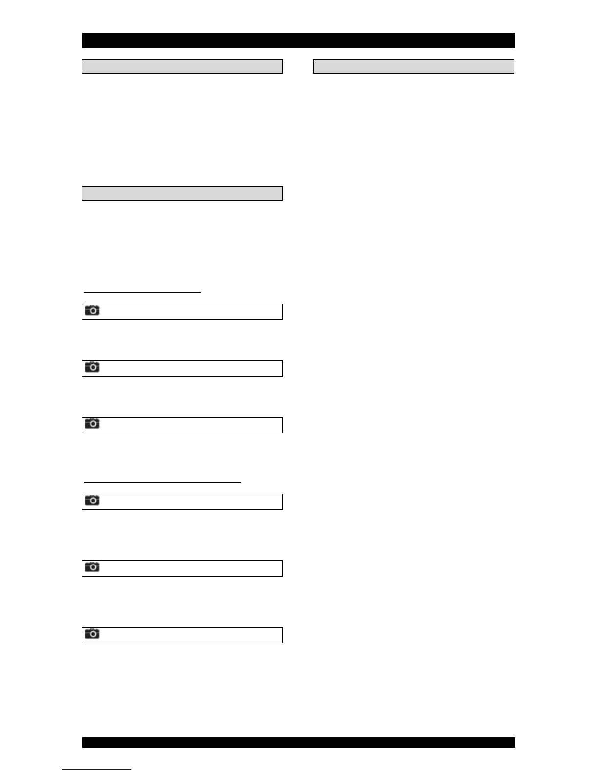
WITH FACTORY BYPASS (optional)
Picture 7.a
SERVICE POSITION
= inlet valve to water filter is OPEN
= outlet valve from water filter is OPEN
Picture 7.b
BYPASS POSITION
= inlet valve to water filter is CLOSED
= outlet valve from water filter is CLOSED
Picture 7.c
MAINTENANCE POSITION
= inlet valve to water filter is OPEN
= outlet valve from water filter is CLOSED
WITH 3-VALVE BYPASS SYSTEM (not included)
Picture 8.a
SERVICE POSITION
= bypass valve is CLOSED
= inlet valve to water filter is OPEN
= outlet valve from water filter is OPEN
Picture 8.b
BYPASS POSITION
= bypass valve is OPEN
= inlet valve to water filter is CLOSED
= outlet valve from water filter is CLOSED
Picture 8.c
MAINTENANCE POSITION
= bypass valve is OPEN
= inlet valve to water filter is OPEN
= outlet valve from water filter is CLOSED
SANITIZING THE WATER FILTER
If the power supply to the water filter is disconnected for a
longer period of time, we recommend, when the power
supply is re-established, to manually initiate a complete
regeneration.

HYDRAULIC FLOW DIAGRAMS - O2xydizer
Page 10
SERVICE BACKWASH
PURGE
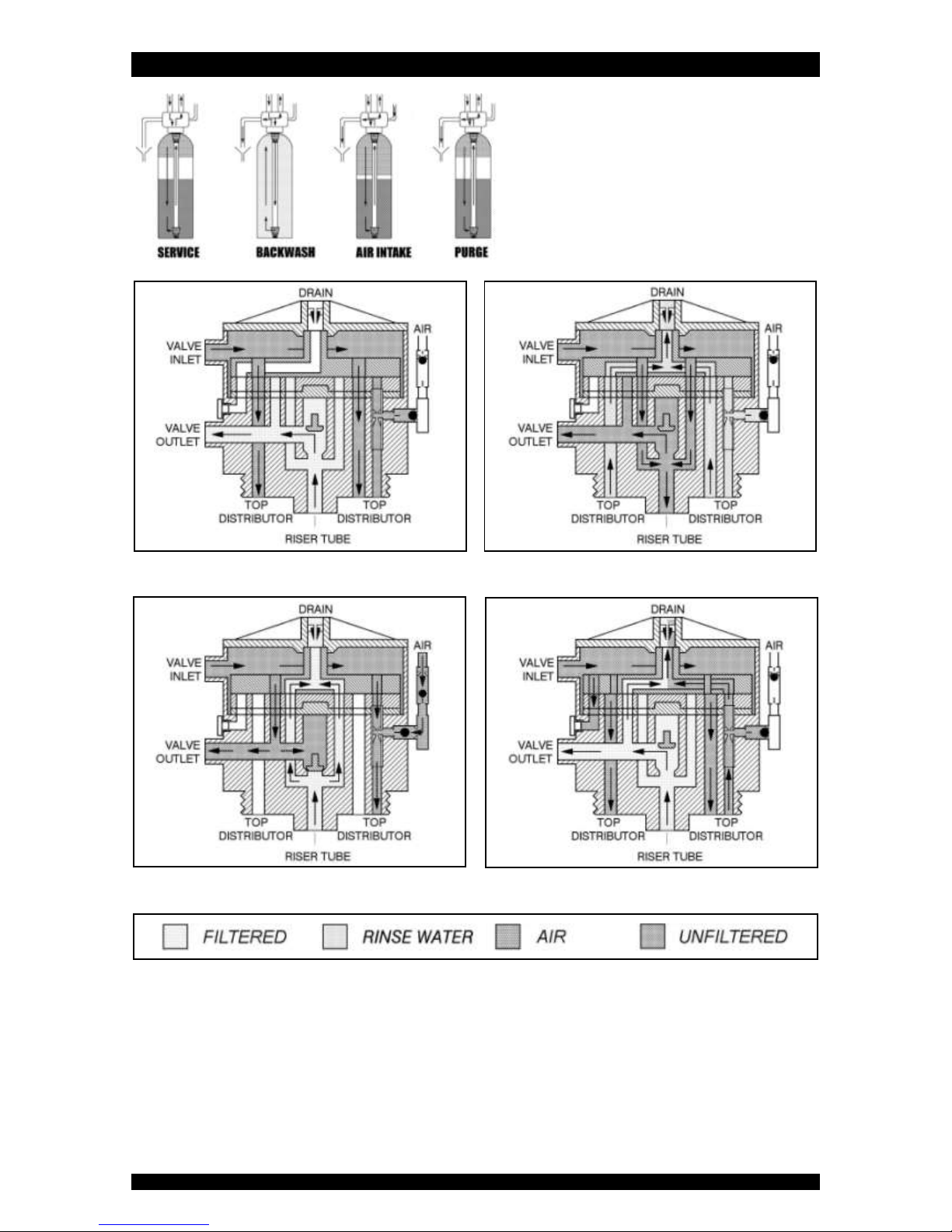
HYDRAULIC FLOW DIAGRAMS - O2xydizerPRO
Page 11
SERVICE BACKWASH
AIR INTAKE PURGE

TROUBLESHOOTING
Page 12
PROBLEM
CAUSE
SOLUTION
Untreated water to
service
Open or defective bypass
Close or replace bypass
Water filter in regeneration
Wait until regeneration finishes or manually
advance regeneration to end
Excessive water usage
Initiate regeneration manually
Change in raw water composition
Verify composition of incoming untreated
water and adjust regeneration frequency
accordingly
Water filter fails to start a regeneration
Refer to problem “Water filter fails to start a
regeneration”
Valve body and timer out of synchronisation
Synchronise valve body and timer
Decreasing filter capacity of filter medium
Clean or replace filter medium
Loss of filter medium
Refer to problem “Loss of filter medium”
Leak at riser tube
Verify that riser tube is seated correctly and is
not cracked
Low levels of
contaminant in treated
water
Bypass not completely closed
Close bypass
Excessive service flow rate
Lower service flow rate
Increase filter capacity by increasing volume of
filter media
Leak between riser tube and control valve
body
Verify that riser tube is sealing off correctly
inside control valve body
Treated water is
slightly non-
transparent and/or
effervescent
Passage through compressed air chamber
causes water to become highly oxygenated
Totally harmless for quality of the treated
water and will disappear rapidly if water is left
standing for a moment
Water filter fails to
start a regeneration
Faulty electrical supply
Verify electrical service (fuse, transformer,...)
Defective PCB
Replace PCB
Defective drive motor
Replace drive motor
Regeneration frequency not programmed
Program regeneration frequency
Loss of water pressure
Build-up of impurities in pressure tank
Clean filter medium and control valve; increase
regeneration frequency
Plugged lower and/or upper distributor
Verify that distributors are free of debris
Crushed lower and/or upper distributor
Replace distributor(s)
Control valve cycles
continuously
Defective drive motor micro switch
Replace drive motor micro switches
Defective PCB
Replace PCB
Drain line from control
valve flows
continuously
Water filter in regeneration
Wait until regeneration finishes or manually
advance regeneration to end
Faulty electrical supply
Verify electrical service (fuse, transformer,...)
Defective PCB
Replace PCB
Defective drive motor
Replace drive motor
Valve body and timer out of synchronisation
Synchronise valve body and timer
Loss of filter medium
Lower and/or upper distributor damaged
Replace distributor(s)
Leak between riser tube and upper distributor
Verify that riser tube is seated correctly and is
not cracked
Water filter fails to
backwash
Low operating pressure
Check operating pressure; must be higher than
2,0 bar
Insufficient water supply
Check water supply (flow rate/dynamic
pressure)
Restricted drain line
Verify drain line for kinks or restrictions
Excessive build-up of impurities in pressure
tank
Clean or replace filter medium and control
valve; increase regeneration frequency
Plugged backwash flow control
Clean or replace backwash flow control

ELECTRICAL WIRING DIAGRAMS
Page 13
= position switches
= power lead
= drive motor
= key pad

DEFAULT PARAMETER SETTINGS
Page 14
Model
O2xydizer
O2xydizerPRO
Filter medium, quantity (Cuft - Ltr)
1 - 28
2 - 56
1 - 28
2 - 56
Interval (days)
4
4
4
4
Cycle 1: BACKWASH (min)
10
10
10
10
Cycle 2: AIR INTAKE (min)
0
0
10
15
Cycle 3: PURGE (min)
2
2
2
2
Regen @
0:00
0:00
0:00
0:00

Page 15
EXPLODED VIEW - SYSTEM
Page 16

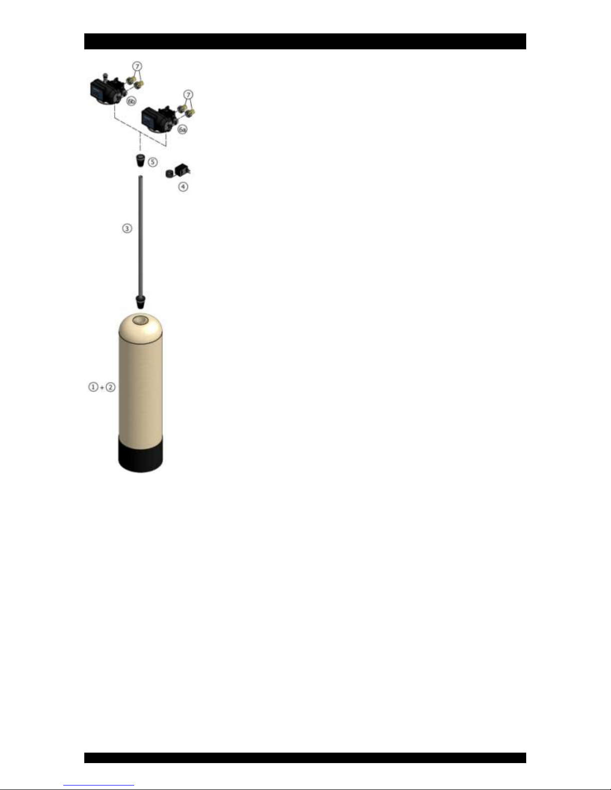
EXPLODED VIEW - SYSTEM
Page 17
Item
PN
Description
Remark
(*)
1
PT/1040/BA
Pressure tank 10x40
1 Cuft
PT/1252/BA
Pressure tank 12x52
2 Cuft
2
A8006
Birm
multiple of 1 Cuft (28 Ltr)
3
38534
Riser tube assembly
to be cut to length
4
28/298/11
Transformer 230/24V - 50 Hz, 24VA, EuroT plug
5
287/166
Top distributor
6a
2400TF/JN/AUX
Control valve
O2xydizer 1 Cuft
2400TF/JQ/AUX
Control valve
O2xydizer 2 Cuft
6b
2400TF/J5N/AUX/AIR
Control valve
O2xydizerPRO 1 Cuft
2400TF/J5Q/AUX/AIR
Control valve
O2xydizerPRO 2 Cuft
7
568/303/6
Connection kit 3/4”BSP male
(*) Recommended Spare Part
EXPLODED VIEW - TIMER HEAD
Page 18

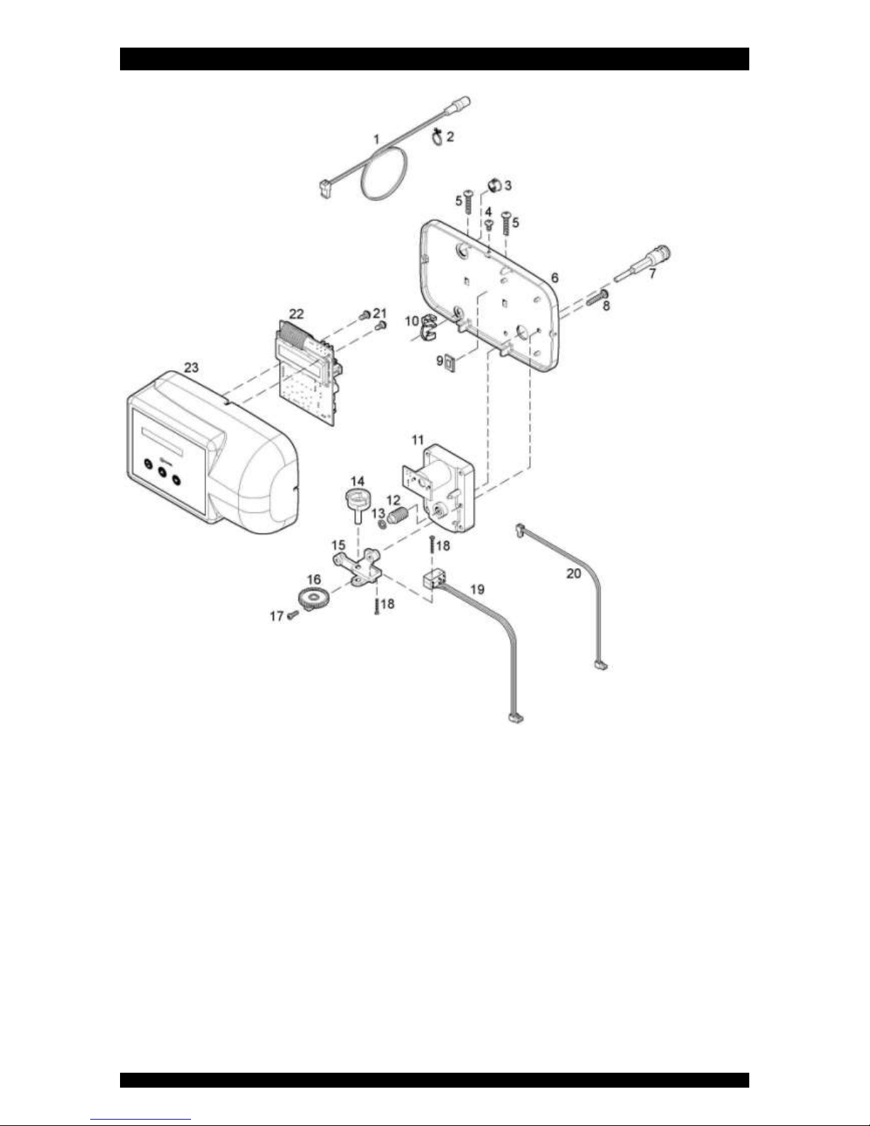
EXPLODED VIEW - TIMER HEAD
Page 19
Item
PN
Description
Remark
(*)
1
70971
Power lead with plug
2
72263
Clamp
3
28/244/1
Plug (large)
4
71502
Screw, timer cover (3x)
5
15/222
Screw, back plate (2x)
6
70962
Back plate
7
2100/206
Drive shaft
8
15/222
Screw, drive motor assy (2x)
9
28/245/4
Cable clamp
10
71502
Strain relief, power lead
11
72261
Drive motor
12
568/227/2
Worm
13
19/48
Retaining ring
14
70965
Switch cam
15
568/386
Bracket, micro switches
16
568/310
Gear, switch cam
17
15/184/7
Locking screw, switch cam
18
15/173/12
Screw, micro switches (2x)
19
72451
Micro switch assy
20
71679
Cable set, drive motor
21
15/102
Screw, PCB (2x)
22
72703
Printed Circuit Board
23
72614
Timer cover assembly
(*) Recommended Spare Part
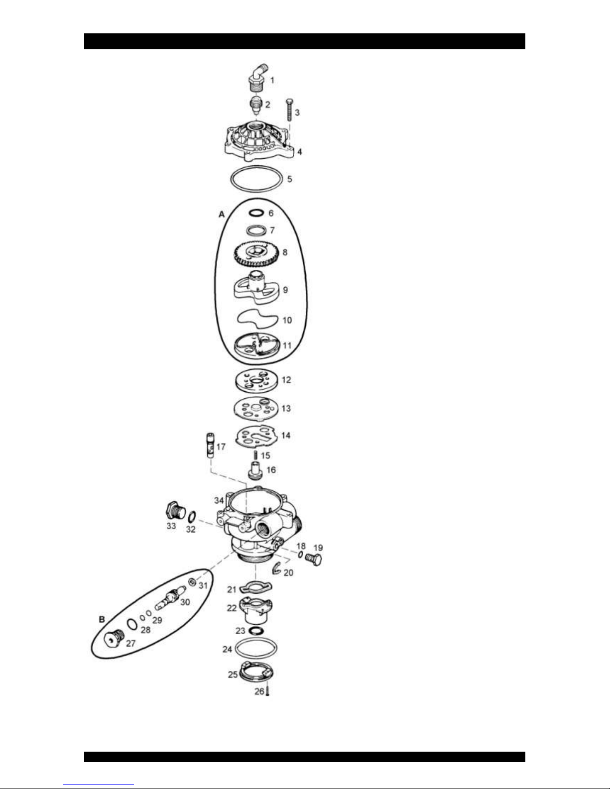
EXPLODED VIEW - VALVE BODY - O2xydizer
Page 20
Table of contents
Other Aquion Water Dispenser manuals


Popular Water Dispenser manuals by other brands

Haws
Haws HW Series Fitting and operating instructions

Everpure
Everpure MR-225 Specifications

Halsey Taylor
Halsey Taylor OVL-II Series owner's manual

Morton
Morton MSD45E install and operation manual

Pro Pond
Pro Pond UV110 Advantage Instructions for installation and use

GE
GE Profile FQROPF use and care manual


ION
ION TS Series Technical & service manual

Flurida
Flurida FDFB10501 User instructions

MERQUIP
MERQUIP COSMETAL H2OMY TOP A Installation, use and maintenance handbook

Haws
Haws 1210S Installation, operation & maintenance instructions

vitapur
vitapur VWD2636W-3 Use & care guide

Natural Choice
Natural Choice ION TS Series owner's manual