ARAG 520005 Quick start guide

FOAM MARKER
520005
520005C
5200052
5200052C
02
INSTALLATION, uSE AND MAINTENANCE

LEGEND SYMBOLS
=Generic danger
=Warning
This manual is an integral part of the equipment to which it refers and must accompany the equipment in
case of sale or change of ownership. Keep it for future reference; ARAG reserves the right to modify the
specications and instructions regarding the product at any time and without prior notice.

3
CONTENTS
Legend symbols ............................................................................................................................ 2
1 Product description ...................................................................................................................... 4
1.1 Intended use ......................................................................................................................... 4
2 precautions ..................................................................................................................................... 4
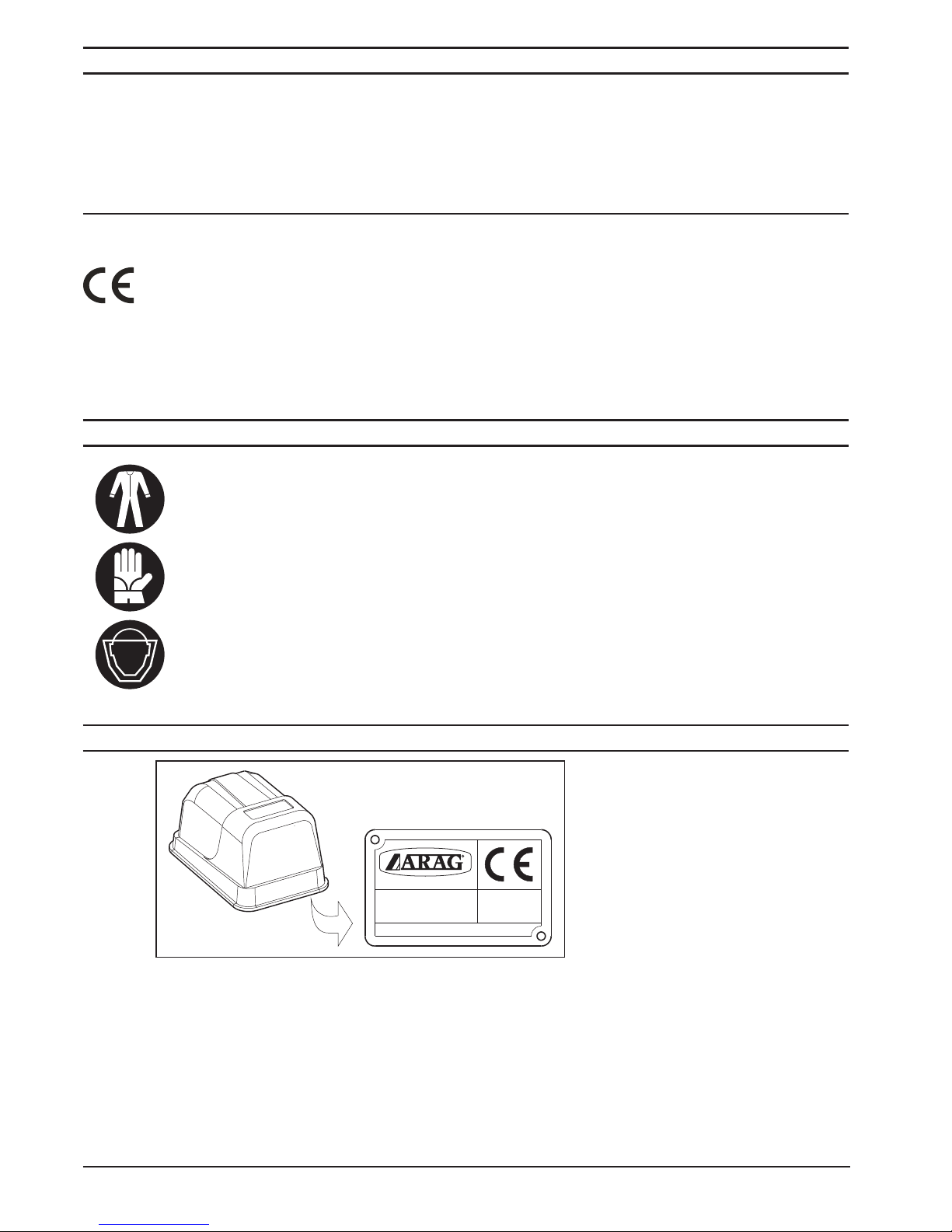
3 Identication................................................................................................................................... 4
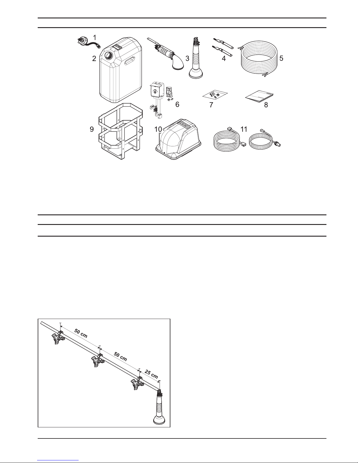
4 Contents of the packaging.......................................................................................................... 5
5 Installation....................................................................................................................................... 5
5.1 Precautions............................................................................................................................ 5
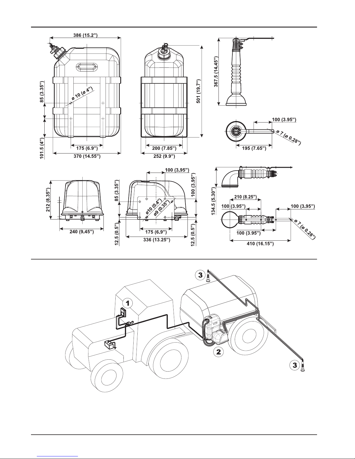
5.2 Overall dimensions - mm (inches)..................................................................................... 6
5.3 Assembly diagram................................................................................................................ 6
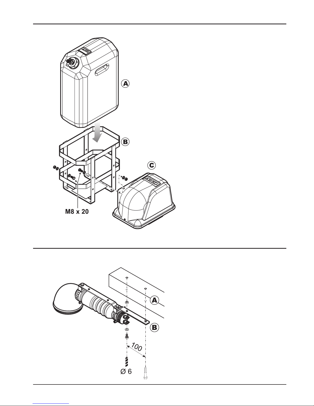
5.4 Installing tank and compressor unit .................................................................................. 7
5.5 Installing the foam markers ................................................................................................ 7
5.6 Mounting the pneumo-hydraulic circuit............................................................................. 8
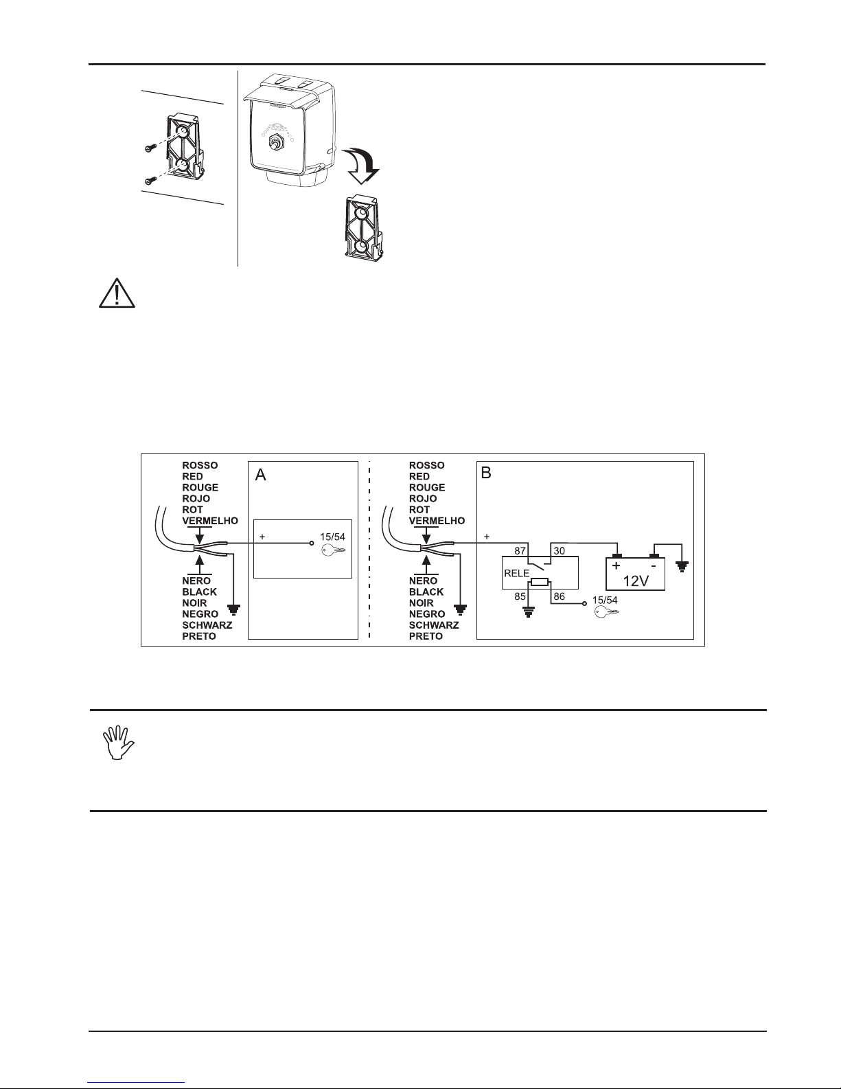
5.7 Installing the control box ..................................................................................................... 9
5.8 Accessory connections: positioning the foam marker control kit ................................. 9
5.9 Final testing ........................................................................................................................... 9
6 Use................................................................................................................................................... 10
6.1 Discharging remaining pressure...................................................................................... 10
6.2 Control devices ................................................................................................................... 10
6.3 Preliminary checks............................................................................................................. 10
6.4 Preparing foaming solution............................................................................................... 10
6.5 Starting and operating........................................................................................................11
6.6 Topping up liquid .................................................................................................................11
6.6.1 Foaming agents...................................................................................................................11
7 Maintenance / diagnostics / repairs ....................................................................................... 12
7.1 Max. pressure valve ........................................................................................................... 12
7.2 Machine down for up to 7 days ........................................................................................ 12
7.3 Machine down for up to 30 days...................................................................................... 13
7.4 Machine down for longer than 30 days .......................................................................... 13
7.5 Reactive maintenance....................................................................................................... 14
7.6 Pipe repairs ......................................................................................................................... 14
7.7 Fuse replacement............................................................................................................... 14
7.8 Troubleshooting .................................................................................................................. 15
7.9 Problems due to the solenoid valves locking up ........................................................... 16
8 Technical data .............................................................................................................................. 16
9 End of life disposal ..................................................................................................................... 16
10 Spare parts.................................................................................................................................... 17
11 Guarantee terms .......................................................................................................................... 22

4
1 Product descriPtion
The foam marker transforms a mixture of foaming agents, added to clean water, into a foam that
can be seen on the ground.
The foam, which is inert, visually marks out previously treated areas of crop, thus avoiding double
treatments, product wastage and potential damage to the crop.
1.1 Intended use
Device designed for installation to crop-spraying, spraying agricultural machinery
and forestry machinery.
This equipment has been designed and manufactured in compliance with the fol-
lowing directives and standards:
•2004/108/CE and subs. mod. (Electromagnetic Compatibility);
•97/23/CE and subs. mod. (Pressure equipment);
•98/37/CE and subs. mod. (Machinery);
EN ISO 14982 (Agricultural and forestry machinery - Electromagnetic Compatibility -
Test methods and acceptance criteria).
2 Precautions
•Foaming agents in general are potentially toxic!
•Only use the foam marker outdoor or in well ventilated environments wearing
the required individual protection gears, overall, gloves and mask.
•Never expose the equipment to water jets.
•Never use solvents or petrol to clean the external parts of the container.
•Do not use direct jets of water for cleaning the device.
•Comply with the specic power supply voltage (12 Vdc).
•In case of electric arc welding, make sure that the power supply to the device
is disconnected; if necessary, disconnect the power supply cables.
•Use only original ARAG spare parts or accessories.
3 identification
42048 RUBIERA (RE)-ITALY
Modello - Model :
Matricolan°:
Serial number :
Anno
Year
Alimentazione-Power:
TRACCIAFILE
FOAM MARKER
Volt: 12
A: 9
00000/00
On all request for spare parts,
give the serial number and year
of manufacture of the foam
marker given on the identication
plate.
Fi g. 1

5
4 contents of the Packaging
5 installation
5.1 Precautions
When installing the foam marker it is necessary to observe a few essential rules:
•When xed, the compressor unit should be sheltered from sprayed products or stones which
can be thrown by tractor wheels.
•On seeders, install the electric-compressor unit sheltered from areas that are too dusty.
•Install the foam marker at bar ends using the supplied supports at a distance from the last
spraying nozzle equal to half the distance of one nozzle to the other (Fig. 3).
•The foam must fall in an area sheltered from the nozzle and the point where it falls must mark
the area treated by the boom.
•Fix the pipes of the pneumo-hydraulic system to the framework with clamps, in a position pro-
tected from possible impact with the ground or with the boom framework.
•At the joints of the booms the pipes must be of
such a length as to allow the booms to open and
close without damaging the pipes.
•Place the tank upright with the cap easily acces-
sible for lling and adjusting the ow rate.
•Apply the tank so as to make it possible to be
removed for periodical washing.
•The compressor cover should be easily removed
for maintenance operations.
1 Tank plug with max. pressure valve
2 Foaming liquid tank
3 Foam markers
4 Vertical foam marker brackets
5 Air-liquid connecting pipes
6 Control box
Fi g. 3
7Accessory/spare part kit
8Instructions handbook
9Tank holder basket
10 Compressor/solenoid valve unit
11 Complete harnesses
Fi g . 2

6
5.2 Overall dimensions - mm (inches)
5.3 Assembly diagram
1 Control box
2 Tank and compressor unit
3 Foam makers
Fi g. 4
Fi g. 5

7
5.4 Installing tank and compressor unit
Tank and compressor unit can be installed onto the machine in two different ways:
5.5 Installing the foam markers
Install the foam markers at bar ends as specied below:
Horizontal foam markers
Fi g. 6
Fig. 7a
1Fix the compressor unit (C) to the tank
holder basket (B) and then install the
assembly onto the machine.
2Install compressor unit (C) and tank
holder basket (B) separately.
Should this be the case, the compressor
and the basket can be directly installed
on the machine.
Always use the supplied screws.
• Drill two Ø 6 mm holes at a distance of 100
mm on bar (A).
•Fix the bracket (B) to the bar with the sup-
plied M6 screws.
•Repeat the operation with the other boom.

8
Vertical foam markers
5.6 Mounting the pneumo-hydraulic circuit
- Connect the white tube (air) and the blue tube (uid) to the foam marker which is the farthest from
the compressor unit. Ensure that each tube is connected to a connector of the same color.
- Lay the piping along the framework of the boom as far as the electric compressor unit, leaving
plenty of it by the joints.
- Connect the tubes to the compressor unit ensuring that each tube is connected to a connector
of the same color.
- Connect the foam marker which is the nearest to the compressor unit and repeat the above
procedure.
- Connect the dark blue pipes (liquid) and the white ones (air) to the ttings of the same colour on
the tank cap.
- Cap the tank.
• Drill two Ø 6 mm holes at a distance of 100 mm
on bar (A).
•Fix the bracket (B) to the bar with the supplied
M6 screws.
•Fit the foam maker (D) onto the knurled section
of the bar (B) and x with the supplied screw
(E).
•Repeat the operation with the other boom.
Fig. 7b
Fi g. 8

9
5.7 Installing the control box
If the contact 15/54 (auxiliary) of the starter key can withstand a continuous load of
10A, make the connections of Fig. 10 section A. Otherwise, insert a relay as shown in
Fig. 10 section B.
Minimum cable cross-section: 2,5 mm².
CAUTION: so as not to run the risk of short-circuiting, do not connect the supply
cable connector until installation has been completed.
•Fix the electric cables, making sure that the connections are mounted in a protected
position.
Fi g. 10
•Connect the control box to the compressor unit using the supplied cable.
5.8 Accessory connections: positioning the foam marker control kit
To use the foam marker with a BRAVO computer install the foam marker kit as de-
scribed in the instructions supplied with the very kit (please refer to ARAG General
Catalogue for part numbers).
5.9 Final testing
1) Insert some litres of water into the tank.
2) Screw the cap onto the tank fully.
3) Move the selector (A, Fig. 12) to the right and start the compressor unit.
4) Ensure that uid comes out from the right foam marker after some seconds.
5) Check the correct seal of the hydraulic couplings.
6) Shift the selector to the left (A, Fig. 12) and start the compressor unit.
7) Ensure that foam is coming out from the left maker.
8) Check that no hydraulic connections are leaking.
9) Interrupt delivery by setting the switch to its central position (OFF).
10) Depressurize the tank as indicated in par. 6.1 - Discharging remaining pressure.
11) Empty the water from the tank.
12) Clean the circuit as described in chap. 7 - Maintenance / diagnostics / repairs.
•Install the control box into the driver’s cabin: position
the fastening slide with the screws (Fig. 9) where
the driver can easily see and reach the box provided
that it is far from any moving parts; secure the con-
trol box to the slide by inserting and pushing it down
until it locks in place.
•Fix the wirings so that they do not come into contact
with moving parts.
•Connect the supply cable to the starter key 15/54.
Fi g. 9

10
6 use
6.1 Discharging remaining pressure
Fully depressurize the system as described below before removing the tank plug:
6.2 Control devices
6.3 Preliminary checks
After a long period of disuse and before every new use, check the tightness of the
ttings.
6.4 Preparing foaming solution
•Pour an amount of concentrated foaming liquid into the tank according to the instructions
given on the package of the product (see par. 6.6).
•Add clean water to ll the tank, using a pipe inserted down to the bottom of the tank so as
to mix the product well and prevent foam from forming.
•Screw on the cap and tighten it carefully.
•For use during the winter, add automotive antifreeze in the amount specied on the anti-
freeze package.
•Cut off the supply to the foam marker.
•Pull the red pin of the relief valve onto the tank
plug and then discharge any residue pressure as
shown in the gure.
aLever control switch for foam delivery
(Left / Off / Right).
BPilot lights checking and controlling the treated
portion.
Fi g. 11
Fi g. 1 2

11
6.5 Starting and operating
Fi g. 1 3
6.6 Topping up liquid
•Depressurize the tank as indicated in par. 6.1 - Discharging remaining pressure.
•Rell with liquid, observing the procedures described in the par. 6.4 - Preparing foaming
solution.
•Use only ARAG foaming agents.
•IN CASE OF DAMAGES TO THE FOAM MARKER CAUSED BY NON AUTHORIZED
FOAMING AGENTS, ALL WARRANTY CLAUSES WILL BECOME NULL AND VOID.
6.6.1 Foaming agents
CODE CONTENT PACKAGES
520050 5 lt / 1.32 US gal. tank
520035 25 lt / 6.6 US gal. tank
520033 200 Kg / 441 lb barrel
•Operate the selector lever (A, Fig. 12) onto the control box and
start the compressor.
•The indicator turns on and the circuit reaches the operating
pressure after a few seconds causing the foam to come out
from the selected foam maker.
•Adjust the intensity of the foam outlet, using the ow-rate
regulator on the tank cap (Fig. 13).
•During use it is possible to alternate the right- or left-hand
foam nozzle by moving the selector lever.
•To interrupt foam marker operation, set the switch to its central
position (OFF).

12
7 Maintenance / diagnostics / rePairs
7.1 Max. pressure valve
Max. pressure valve onto the tank plug is maintenance free.
The action of the pressure discharge pin onto the tank plug avoids any clogging of the relief valve
and - at the same time - ensures its proper operation.
7.2 Machine down for up to 7 days
For periods of disuse up to 7 days, proceed as follows:
Horizontal foam markers
•Fully depressurize the tank as shown in Par. 6.1
•Slacken the band (B) and remove the diffusor (A). Only for horizontal foam markers
(Fig. 14a): completely slacken the bands and remove the diffuser in the arrow’s
direction.
•Wash the diffuser (A) with water.
•Remove the grid (C) turning it anticlockwise.
•Extract the sponge (D) from the generator (E).
•Carefully wash the foam diffusers and sponge with water.
•Reassemble the parts taking care when inserting the sponge that must go into its seat
freelyand without compression, as this may compromise foam marker operation.
•Repeat the above operations for the other foam marker as well.
Fig. 14b
Fig. 14a
Vertical foam markers

13
7.3 Machine down for up to 30 days
For periods of disuse up to 30 days, proceed as follows:
•Depressurize the tank as indicated in par. 6.1 - Discharging remaining pressure.
Fig. 15
•Depressurize the tank as indicated in par. 6.1 - Discharging remaining pressure.
Fig. 16
7.4 Machine down for longer than 30 days
For long periods of inactivity, proceed as follows:
•Run the operations described in par. 7.3 - Machine down for up to 30 days.
•Clean the compressor unit:
- Remove the cover by taking out the screws (A).
- Clean the inside with compressed air (wearing a face-mask and safety goggles).
- Spray the self-cleaning liquid for electrical contacts through the slots on the electric motor.
- Reinstall the cover.
Fi g. 1 7
•Slacken and remove the cap (C).
•Remove tank (A) and wash with clean water.
•Wash the bottom lter (D) with clean water.
•Fit the tank into the retaining basket.
•Add a few litres of water into the tank, put the cap back on.
•Restore the electrical connections.
•Wash the hydraulic circuit, operating alternately the lever
selector in the position corresponding to the boom section
involved until clean water comes out of the diffusers.
•Unscrew and remove the cap and immediately empty the tank of any remaining
water.
•Remove the water/air hoses from the cap and connect them to each other with
the provided snap tting as shown in Fig. 16.
•Empty the hydraulic circuit by operating the lever selector in the position corre-
sponding to the boom section involved until only air comes out of the diffusors.
•Fit all the parts back together to restore the initial conditions.
•Clean the diffusers as described in par. 7.2 - Machine down for up to 7 days.

14
7.5 Reactive maintenance
To ensure dense and lasting formation of foam, replace the sponges code 520000.160
(D, Fig. 14a +14b) every year.
7.6 Pipe repairs
If the hoses break, repair them with one of the snap ttings (code 520005.352 or
520005.353) provided with the package.
Proceed as follows:
Fig. 18
7.7 Fuse replacement
Before replacing the fuse, disconnect the control box from the battery.
Fig. 19
•Lift the fuse holder cap (A) onto the power cable.
•Replace the old fuse (B) with a new one of the same
type (10 A): the package includes a spare fuse.
•Recap and check for proper cap position.
•Use a pair of scissors to trim the
broken ends of the hose.
•Fit the two ends into the tting.

15
7.8 Troubleshooting
DEFECT CAUSE REMEDY
The compressor unit does not work,
the warning lights do not turn on
No power to the control box
•Checkthefuse.
•Checktheelectricalconnectionsof
the control box.
Electric connection between control
box and compressor cut off
•Checktheconnectionsbetweenthe
control box and the electric compres-
sor.
No foam coming out from the foam
marker
The tank will not pressurize
•Closethetankcapproperly.
•Checkthetightnessofthepipescon-
necting the compressor with the cap.
Break in the pneumo/hydraulic circuit
•Checktherearenocracksinthe
darkblue pipe inside the tank (from
the lter to the plug) and on the outer
pipes.
•Cleanthebottomlterofliquid.
•Checkforanyconstrictionsalongthe
pipes.
Foam formation is not good
Sponge dirty or hardened •Cleanorreplacethespongeinthe
generator.
Water-foaming agent mix old •Redothewater-foamingagentmix.
Flow-rate adjustment wrong
•Usetheow-rateregulatoronthe
tank cap to obtain a sufficiently dense
foam.
Constrictions in pipes •Checkthetubestothefoammarkers.
Bleed air from the max. pressure valve
onto the plug Constrictions in the pipes •Checkthetubestothefoammarkers.
Air or liquid leaks from the ttings Incorrect tting seal
•Detachthehoseatthesnaporthre-
aded ttings and shorten it by around
10 mm to eliminate deformations at
the tting.
The compressor unit does not work,
the warning lights ash only once +/- power reversed •Repairtheelectricconnection.

16
7.9 Problems due to the solenoid valves locking up
In case of air or uid leakages from the connector or if the foam comes out from a non-selected
foam generator, solenoid valves (Fig. 21) might be stuck.
Before doing anything else, disconnect the control box from the battery.
Free up the solenoid valves as follows:
Fig. 20
For not specied problems, contact your dealer or the ARAG service centre.
8 technical data
Description Value
Power supply voltage 12 ÷ 14 Vdc
Current draw (at 12 Vdc) 9 A
Working temperature 0 °C ÷ +40 °C / +32 °F ÷ +104 °F
Tank capacity 27 l
Working pressure (at 12 Vdc) ≈ 0,75 bar
Max. pressure valve setting 1 bar
Water/foam agent solution consumption* 35 l/h max
Total weight excluding packing 17,5 kg
Noise level 70 dB (A)
*
Using foaming agent ARAG at the concentration given on the package,
(see par. 6.6.1.)
9 end of life disPosal
To be disposed in compliance with the legislation in force in the country in question.
•Disconnect the tubes from the compressor unit to the foam
generators.
•Blow with compressed air into the unions of the solenoid
valves towards the compressor (Fig. 20).
•If the problem persists, contact your local service
centre.

17
520005 - 5200052 - 520005C - 5200052C - 520005.900
10 sPare Parts

18
520005.060

19
520005.080

20
520005.260
520004.262
This manual suits for next models
3
Table of contents
Other ARAG Farm Equipment manuals