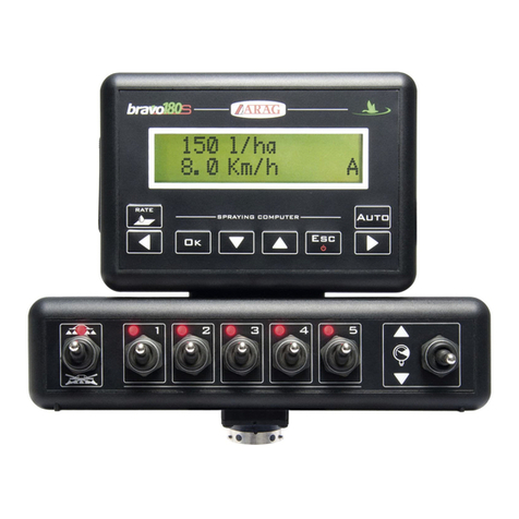
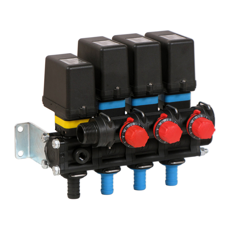
ARAG bravo 350 Series Service manual

BRAVO 350 SERIES COMPUTER
ORCHARD SPRAYER
DIRECT CONNECTION
Software rel. 1.3.x
INSTALLATION, USE AND MAINTENANCE
467354XXXX
WWW.ROLTRONIK.PL

2
• LEGEND OF SYMBOLS
=Generic danger
=Warning
This manual is an integral part of the equipment to which it refers and must always accompany it even in case of sale or transfer. Store it for any future
consultation; ARAG reserves the right to modify specifications and instructions of the product at any time and without prior notice.
LEGEND OF SYMBOLS
WWW.ROLTRONIK.PL

3
Par. 7.3
Fast data reset Scroll menu items or Increase/
decrease data
Confirm menu access or
data change
Exit menu or data
change
• Legend of symbols ................................................................. 2
• Manual foreword and use ...................................................... 4
• Manual use modes.................................................................. 4
• LIMITATIONS ........................................................................... 4
• Responsibility ......................................................................... 4
1 Risks and protections before assembly............................... 4
2 Intended use............................................................................ 4
3 Precautions ............................................................................. 4
4 Package content ..................................................................... 5
5 System recommended composition ..................................... 5
5.1 Monitor position.................................................................6
5.2 Bracket fixing ....................................................................6
5.3 Control unit position ..........................................................6
5.4 Installation of ultrasonic sensors.......................................7
6 Wiring connections................................................................. 9
6.1 General precautions for a correct harness position ..........9
6.2 Power supply connection..................................................9
6.3 Connection to the control unit valves and to the solenoid
section valves ...............................................................10
6.4 Connection of ultrasonic sensors....................................11
6.5 Connection of sensors and available functions...............12
6.6 Power supply connection................................................12
7 Setting....................................................................................13
7.1 Tests and checks before setting......................................13
7.2 Computer switching on/off ..............................................13
7.3 Use of keys for setting ....................................................14
8 Advanced setup .................................................................... 15
8.1 Ultrasonic configuration ..................................................16
8.2 Sections configuration.....................................................16
8.3 Valves configuration........................................................17
8.4 Bulkheads .......................................................................18
8.5 Flowmeter .......................................................................19
8.6 Pressure sensor..............................................................19
8.7 Delivery cal. sensor.........................................................19
8.8 Tank level........................................................................20
8.8.1 Tank level - Manual Mode ............................................... 20
8.8.2 Tank level - Level sensor mode....................................... 20
8.8.3 Tank level - Filling flowmeter mode ................................. 21
8.9 External device ...............................................................22
8.10 Access level ....................................................................23
8.11 Rev counter.....................................................................24
8.12 Setup check after Advanced setup end ..........................24
9 User setting ........................................................................... 25
9.1 Job selection...................................................................27
9.2 Current Job data .............................................................27
9.3 Jobs setup.......................................................................27
9.4 Booms setup...................................................................28
9.5 Nozzles setup .................................................................28
9.6 Intervention sensibility.....................................................29
9.7 Working parameters........................................................30
9.7.2 Nozzles wear check......................................................... 30
9.7.3 Min. spraying speed ........................................................ 30
9.7.4 Regulation lock type ........................................................ 30
9.8 Rate controller.................................................................30
9.9 Tank ................................................................................31
9.10 Speed..............................................................................32
9.10.1 Source - Wheel sensor.................................................... 33
9.10.2 Source - GPS .................................................................. 33
9.11 Flowrate correct. factor ...................................................34
9.12 Press. sensor zero value ................................................34
9.13 Totalizers.........................................................................34
9.14 Test .................................................................................35
9.14.1 Speed simulation............................................................. 35
9.14.2 Signal test........................................................................ 35
9.14.3 Battery voltage................................................................. 35
9.14.4 Display............................................................................. 35
9.14.5 Keyboard & Switches ...................................................... 36
9.14.6 Ultrasonic sensors........................................................... 36
9.14.7 GPS data......................................................................... 36
9.14.8 Constant pressure mode ................................................. 36
9.14.9 Monitor hardware version - Monitor software version...... 36
9.15 User preferences ............................................................37
9.15.1 Sound alarm .................................................................... 37
9.15.2 Sound keyboard .............................................................. 37
9.15.3 Date & Time..................................................................... 37
9.15.4 Display contrast............................................................... 37
9.15.5 Filling calculation ............................................................. 37
9.15.6 Data display..................................................................... 37
9.16 Data logger .....................................................................38
9.17 Ext. device log.................................................................38
9.18 Load/save setup..............................................................39
9.18.1 Load configuration from USB .......................................... 39
9.18.2 Save configuration to USB .............................................. 39
10 Use ......................................................................................... 40
10.1 Controls on computer......................................................40
10.2 Keys to manage the boom sections (1 Fig. 88) ..............40
10.3 Control, selection or modification keys (2 - 3 Fig. 88).....41
10.4 Switches to control bulkhead actuators and auxiliary
devices (4 Fig. 88) ........................................................41
10.5 Switches to operate valves in the control unit (5 Fig. 88)41
10.6 Display ............................................................................42
10.7 Treatment preliminary settings........................................43
10.8 Application rate regulation ..............................................44
10.8.1 Automatic operation......................................................... 44
10.8.2 Manual operation (DEFAULT) ......................................... 44
11 Maintenance / diagnostics / repairs .................................... 45
11.1 Cleaning rules.................................................................45
11.2 Operation errors..............................................................45
11.3 Troubleshooting ..............................................................46
12 Accessories........................................................................... 46
12.1 Pendrive..........................................................................46
13 Technical data ....................................................................... 47
13.1 Computer technical data ................................................47
13.2 Pin-out of Bravo 350 .......................................................47
14 Guarantee terms ................................................................... 48
15 End-of-life disposal .............................................................. 48
CONTENTS
WWW.ROLTRONIK.PL

4
• MANUAL FOREWORD AND USE
This manual provides instructions to assemble, connect and set the computers of the BRAVO 350 family.
Any other information is provided in specific sheets to be used exclusively by the installer, containing specific information of each computer model.
• MANUAL USE MODES
The section of this manual dedicated to the installation contains information for installers. For this reason we have used technical terms
without providing explanations which would be necessary for end users only.
INSTALLATION MUST BE CARRIED OUT ONLY BY AUTHORIZED AND SPECIFICALLY TRAINED PERSONNEL. THE
MANUFACTURER IS NOT RESPONSIBLE FOR ANY OPERATION SPECIFIED IN THIS MANUAL CARRIED OUT BY
UNAUTHORIZED OR UNSKILLED PERSONNEL.
• LIMITATIONS
The descriptions of the assembly phases refer to a "general" computer, so specific models will not be mentioned, unless a certain installation procedure
concerns exclusively one computer type.
• RESPONSIBILITY
The installer must carry out workmanlike installations and ensure to the end user the perfect operation of the whole system both with ARAG
components only and other brands' components.
ARAG always recommends using its components to install control systems.
The installer will be held responsible for any malfunction if he decides to use other brands' components even without actually changing the system
parts or harness.
The compatibility check with components and accessories of other manufacturers shall be carried out by the installer.
If the computer or the ARAG components installed together with other brands' components get damaged because of what stated above, no direct
or indirect warranty will be provided.
1 RISKS AND PROTECTIONS BEFORE ASSEMBLY
All installation works must be done with battery disconnected, using suitable tools and any individual protection equipment
deemed necessary.
Use ONLY clean water for treatment tests and simulations: using chemicals during simulated treatment runs can seriously
injure persons in the vicinity.
2 INTENDED USE
The device you have purchased is a computer which, when connected to a valve or suitable control unit, makes it possible to control all phases of
treatment in agricultural applications directly from the cabin of the farming machine it is installed in.
This device is designed to work on agricultural machinery for spraying and crop spraying applications.
The equipment is designed and manufactured in compliance with UNI EN ISO 14982 standard (Forestry and farming machines -
Electromagnetic compatibility - Test methods and acceptance criteria), harmonized with EMC - 2014/30/EU Directive.
3 PRECAUTIONS
• Do not aim water jets at the equipment.
• Do not use solvents or fuel to clean the case outer surface.
• Do not clean equipment with direct water jets.
• Comply with the specified power voltage (12 VDC).
• In case of voltaic arc welding, remove connectors from BRAVO 350 and disconnect the power cables.
• Only use ARAG genuine spare parts and accessories.
FOREWORD
WWW.ROLTRONIK.PL

5
INSTALLATION
4 PACKAGE CONTENT
1
6
2
3
5
4
DRIFT
CONTROL
UNIT
R
CLOSE
OPEN
L
CLOSE
OPEN
1
actuators
2
3 Power supply connector
4 Connection cable for:
valve) - Control unit with solenoid or motorized section valves - Bulkhead
actuators (if provided)
5 Seals for valve connectors
6 Fixing kit
Sensors, control units and accessories must be ordered separately
(Ref. ARAG general catalog).
5 SYSTEM RECOMMENDED COMPOSITION
T
SMX
1.3 m
3.8 m
3 m
0.7 m
1
US1
US2
G
FP
3
2
4
DRIFT
CONTROL
UNIT
R
CLOSE
OPEN
L
CLOSE
OPEN
5
LEFT
RIGHT
*
*
2 ways 4 / 6 ways
bulkhead version
Legend:
1Connection cable for:
2Control unit (GPcontrol valve)
3Control unit (1 ÷ 6 solenoid section valves) / (1 ÷ 6 motorized section valves)
4 Power cable for Bravo 350
5 Bravo 350 with direct connection
Sensors:
X RPM sensor (in the version with bulkheads there is no RPM sensor)
T Filling flowmeter or Level sensor
S Speed sensor
M Pressure sensor
F Flowmeter
US1÷US2 Ultrasonic sensors
VERSION WITH BULKHEADS:
LEFT Left bulkhead actuator
RIGHT Right bulkhead actuator
WWW.ROLTRONIK.PL

6
INSTALLATION
5.1 Monitor position
BRAVO 350 must be placed in the control cabin of the farming machine. Observe the following precautions:
- Do NOT install the monitor in areas where it would be subjected to excessive vibrations or shocks, to prevent any damage or
accidental use of the control keys;
- Install the device in a visible position within easy reach by hand; bear in mind that the monitor should not obstruct the
operator’s freedom of movement or block his view.
Consider all necessary connections of the computer (chap. 5), the cable length, and make sure there is enough space for
connectors and cables.
Next to each connector there is the symbol identifying the function performed. For any reference to system configuration, see
chap. 5.
268
Ø 6.5
86
40
207
SPRAYING COMPUTER
Ok
Auto
Esc
Clr
F1 F2
F3 F4
222
2
1
3
4
DRIFT
CONTROL
UNIT
R
CLOSE
OPEN
L
CLOSE
OPEN
268 86
255
186.4
Ø 6.5
40
222
2
1
3
4
No. Monitor connection points
1Monitor power supply
2Auxiliary connections
3USB
4Control units - sensors - bulkhead actuators (if provided)
5.2 Bracket fixing
The monitor must be mounted after
having fixed the bracket at the desired
location (the previous paragraph
shows the bracket drilling template).
The bracket must be slid out of the
monitor seat (A, Fig. 5) and fixed using
the supplied screws (B).
Make sure the bracket is securely
mounted, fit the monitor on it, and push
it until it locks in place (C).
DRIFT
CONTROL
UNIT
R
CLOSE
OPEN
L
CLOSE
OPEN
DRIFT
CONTROL
UNIT
R
CLOSE
OPEN
L
CLOSE
OPEN
5.3 Control unit position
The control unit must be fixed with the special brackets supplied and fitted to the unit, positioning it as shown in the manual provided with the assembly.
MAKE SURE TO FOLLOW ALL THE SAFETY INSTRUCTIONS GIVEN IN THE CONTROL UNIT’S MANUAL.
WWW.ROLTRONIK.PL

7
INSTALLATION
5.4 Installation of ultrasonic sensors
The computer does not include the ultrasonic sensors; if you wish to install them, purchase two sensor kits code 46738000.500.
Each kit includes an ultrasonic sensor and an adapter cable.
Computer correct operation is ensured only if ARAG-distributed sensors are used: use of unsuitable sensors not provided by
ARAG automatically voids the warranty. ARAG is not liable for any damage to the equipment, persons or animals caused by
failure to observe the above indications.
WE RECOMMEND INSTALLING SENSORS AT A MINIMUM DISTANCE OF 1 M FROM NOZZLES:
• TO AVOID THAT PLANT DETECTION IS DISTORTED BY THE SPRAYED FLUID.
• TO ALLOW OPENING VALVES WITH THE CORRECT ADVANCE, IN ORDER TO ACCURATELY SPRAY THE PLANT.
nozzles
ultrasonic sensors
Based on system configuration, on your computer and on the height of the plants to be sprayed, agree with the user whether sensors have to detect
the foliage or the trunk of the plant.
Whenever possible, it is recommended to always position sensors in front of the foliage, at a height allowing them to detect its widest part (A, Fig. 7);
should this not be possible, sensors will have to detect the trunk, hence their positions will have to ensure trunk correct detection (B,Fig. 9), excluding
brushwood (Fig. 8, too low position) or part of the foliage (Fig. 10, too high position).
Based on the type of crop and on the expected result, the machine can be configured in different ways:
1) foliage can be detected and sprayed (Fig. 7).
2) trunk only can be detected, hence it will be possible to spray only based on whether the plant is present or not (Fig. 9); this situation occurs when
plant foliage is much taller than the machine and you do not want to build a scaffold for sensor correct positioning.
WWW.ROLTRONIK.PL

8
INSTALLATION
6.4.1 Fixing of sensors on the machine
After having located sensor position, based on the height of the plants you wish to spray, select the fixing point on the machine and fix sensors by
following the instructions provided by the manufacturer.
WARNING: sensors must be always fixed parallel with the ground and at a right angle to the plant to be sprayed (Fig. 11).
WWW.ROLTRONIK.PL

9
INSTALLATION
6 WIRING CONNECTIONS
• Use only the cables provided with the ARAG computers.
• Take care not to break, pull, tear or cut the cables.
• Use of unsuitable cables not provided by ARAG automatically voids the warranty.
• ARAG is not liable for any damage to the equipment, persons or animals caused by failure to observe the above instructions.
Use ONLY the cables and accessories indicated in the catalog, having technical features suitable for the use to be made of
them.
6.1 General precautions for a correct harness position
• Securing the cables:
- secure the harness so that it does not interfere
with moving parts;
- route the harnesses so that they cannot be
damaged or broken by machine movements or
twisting.
• Routing the cables to protect against water
infiltrations:
- the cable branches must ALWAYS be facing
down (Fig. 13).
DRIFT
CONTROL
UNIT
R
CLOSE
OPEN
L
CLOSE
OPEN
DRIFT
CONTROL
UNIT
R
CLOSE
OPEN
L
CLOSE
OPEN
6.2 Power supply connection
Connect the multicore connector to the monitor,
check it is correctly connected, and turn the ring
nut clockwise until connector blocking.
WWW.ROLTRONIK.PL

10
INSTALLATION
6.3 Connection to the control unit valves and to the solenoid section valves
Fix the connectors to the relevant valves according to the
indicated initials.
• Remove the protective cap (1) from the valve.
• Place the seal (2) onto the connector (3), and push the
connector fully on (4): be careful not to bend the contacts
upon insertion on the valve.
• Tighten the screw (5) fully home.
All connectors used for connection to valves
must be equipped with a seal before the
connection is carried out. Check that the seal is
properly positioned to prevent water infiltrations
when using the control unit.
• CONTROL UNIT
LABEL CONNECTION
GMain valve
PControl valve
• SOLENOID SECTION VALVE UNIT
LABEL CONNECTION
1Solenoid section valve no.1
2Solenoid section valve no.2
• MOTOR-DRIVEN SECTION VALVE UNIT
LABEL CONNECTION In case there are more monitor switches than section valves, connect
the cables as indicated in the table below.
No. of section valves Switches to be used
Cables to be
connected
to the valves
23 - 4 1 - 2
42 - 3 - 4 - 5 1 - 2 - 3 - 4
61 - 2 - 3 - 4 - 5 - 6 1 - 2 - 3 - 4 - 5 - 6
1Motor-driven section valve no.1
2Motor-driven section valve no.2
3Motor-driven section valve no.3
4Motor-driven section valve no.4
5Motor-driven section valve no.5
6Motor-driven section valve no.6
ONLY FOR 4- / 6-WAY VERSIONS WITH MOTORIZED VALVES:
USE THIS TYPE OF VALVES ONLY AND EXCLUSIVELY FOR ESPALIER CROPS.
WWW.ROLTRONIK.PL

11
INSTALLATION
6.4 Connection of ultrasonic sensors
Connect the ultrasonic sensor connectors: after having made sure that they are duly inserted, turn ring nut A
until it locks in place.
WARNING: always check the correspondence between sensors (cable marking) and
sections, in order to spray exactly in the point detected by the sensor.
The table below shows the correspondences between sensors and sections.
Sensor position Configuration Marking
of corresponding
Section
sensor cable Section position
2 SENSORS
2 SECTIONS
US1 1
US2 2
2 SENSORS
4 SECTIONS
US1
1
2
US2
3
4
2 SENSORS
6 SECTIONS
US1
1
2
3
US2
4
5
6
WWW.ROLTRONIK.PL

12
INSTALLATION
6.5 Connection of sensors and available functions
ARAG sensors feature a Tyco Superseal®
connector. Insert the connector fully home until
the locking tab clicks into place.
The single products are supplied with the sensor
connecting instructions.
LABEL CONNECTION
FFlowmeter
SSpeed sensor Connection of bulkhead controls:
MPressure sensor LABEL CONNECTION
TFilling flowmeter or Level sensor LEFT Left bulkhead actuator
XRPM sensor (not available in bulkhead version) RIGHT Right bulkhead actuator
6.6 Power supply connection
The package includes the power connector (component 3, Fig. 1) to be connected to the farming machine battery;
Fig. 23 shows the drilling template of the power connector.
Connect the power connector to the battery wires using two 6-mm faston connectors, as indicated in Fig. 21 and Fig. 22.
Use the cable provided with the package (component 2, Fig. 1) to connect the computer to the power supply.
WARNING:
To avoid short circuits, do not connect the power cables to battery before the installation is completed.
Before powering up the computer and control unit, make sure the battery voltage is as specified (12 Vdc).
BRAVO 350 is supplied directly by the farming machine battery (12 Vdc): ALWAYS switch on the computer through the monitor, and then
remember to switch it off using the specific key on the control panel.
If BRAVO 350 remains on for a long time with machine off, the tractor battery could run flat: in case of prolonged breaks of the
machine with engine off, make sure the computer is off, too.
The power source must be connected as indicated in Fig. 24: the computer must be connected directly to the farming machine battery. Do NOT
connect the computer to key-on power (15/54).
BRAVO 350 with direct connection: 10 A
Bravo 350 with actuator control: 20 A
WARNING:
• The power circuit shall ALWAYS be protected by a fuse like the
ones for automotive applications: 10 Amperes / 20 Ampere for
version with bulkhead actuator control.
• All cables connected to the battery shall have a minimum
cross-section of 2.5 sq. mm.
To avoid short-circuits, connect the power cable connector only
after completing installation.
• Use cables with suitable terminals ensuring correct connection
of all wires.
WWW.ROLTRONIK.PL

13
Par. 7.3
Fast data reset Scroll menu items or Increase/
decrease data
Confirm menu access or
data change
Exit menu or data
change
7 SETTING
7.1 Tests and checks before setting
Before computer setting, check:
• that all components are correctly installed (control unit and sensors);
• the correct connection to the power source;
• the component connection (main control unit and sensors).
Failure to correctly connect system components or to use specified components might damage the device or its components.
7.2 Computer switching on/off
• Ordinary switching on
Orchard spraying
computer
Ver. 1.0.0
S
AM
1.53.00m
Software version Job screen
Keep key ESC).
NOTE: The starting screen changes according to the model you have purchased.
• Switching on to activate the advanced setup
+Advanced Setup
>
Language : ...
: Metric
: ...
: ...
: ...
: ...
Unit of measurement
Flowmeter
Ultrasonic configuration
Valves configuration
Bulkhead
Press the key sequence simultaneously until switching Bravo on. Release key ESC keeping pressed the arrow keys until the display shows the
menu Advanced Setup ().
• Switching off
WAIT: saving data
Keep key ESC pressed until the display shows the message WAIT: saving data.
Release the key and wait for the saving process to complete (); after a few seconds the computer turns off.
During switching off do NOT press any other key and do NOT disconnect the power supply until BRAVO 350 turns off.
WARNING: ALWAYS use the special key to switch off the computer; otherwise ALL data concerning the spraying and the
programming will be lost.
SETTING
WWW.ROLTRONIK.PL

14
Par. 7.3
Fast data reset Scroll menu items or Increase/
decrease data
Confirm menu access or
data change
Exit menu or data
change
7.3 Use of keys for setting
Advanced Setup
>
Language : ...
: Metric
: ...
: ...
: ...
: ...
Unit of measurement
Pressure sensor
Ultrasonic configuration
Valves configuration
>
Flowmeter
1
2a
2b
1Use cursor
>
to select the menu you want to
access: move it using the "arrow" keys until
selecting the option you are looking for ().
2Confirm the selection with OK.
DATA SELECTION
3a 4a
Language
>
English
Italiano
2a, ).
3a Press the arrow keys one after the other to select another item; the display will show the selected item.
If it is possible to disable the data press CRL: in this case the display will show the item Disabled.
4a Confirm with OK.
Item quick scrolling: keep one of the arrow keys pressed.
Exit without confirming the change: press ESC.
ACCESS TO A SUBMENU
3b 4b
Advanced Setup
>
Language : ...
: Metric
: ...
Unit of measurement
Ultrasonic configuration
..." (2b, ).
3b Press the arrow keys in succession to move across the menu items. The cursor
>
will move onto the selected one.
4b Press OK to access the submenu.
Item quick scrolling: keep one of the arrow keys pressed.
Exit without confirming the change: press ESC.
ENTERING A NUMERICAL VALUE
56
Constant
RANGE: 00001 <=> 10000 pls/l
00600
5Press the arrow keys in succession to change the value.
To reset the data press CRL.
6Press OK to confirm the data.
Quick increase/decrease of the value: keep one of the arrow keys pressed.
Exit without confirming the change: press ESC.
SETTING
WWW.ROLTRONIK.PL

15
Par. 7.3
Fast data reset Scroll menu items or Increase/
decrease data
Confirm menu access or
data change
Exit menu or data
change
8 ADVANCED SETUP
This operation must be done once only, when installing the computer.
ACCESS TO ADVANCED SETUP (WITH COMPUTER OFF)
• Release the key ESC by keeping the arrow keys pressed until the menu is displayed
+Advanced Setup
>
Language : ...
: MetricUnit of measurement
For a correct use of the keys during setting, refer to
Par. 7.3.
Menu Default Min Max Other values that can be set / Notes
Language English --- --- Italiano - English - Español - Deutsch - FranÇais
Unit of measurement Metric (l/h, km/h, bar) --- --- US (GPA, mil/h, PSI)
Par. 8.1 Ultrasonic configuration
Sensors-boom distance
---
Par. 8.2 Sections configuration
Sections number
Boom Type Single --- --- Double
Booms configuration ... --- --- Item active only if selected as follows:
Boom Type > Double
Section 1 ÷ 6 --- ---
Par. 8.3 Valves configuration
Master --- ---
Pressure regulator --- ---
Section --- ---
Automatic switch-off Yes (M mode) --- --- No (P mode)
Par. 8.4 Bulkhead
Bulkhead mode Manual --- --- Boom status - Half boom status
Par. 8.5 Flowmeter
Type --- --- See Tab. A on page
Min. flowrate alarm
Disabled
Max. flowrate alarm
Disabled
Constant
---
Par. 8.6 Pressure sensor
Type Disabled --- ---
Maximum pressure ---
Item active only if a sensor is selected
Par. 8.7 Delivery cal. sensor Flowmeter --- --- Pressure - Either
Par. 8.8 Tank level
Par. 8.8.1 Mode --- --- --- SELECTED MODE: MANUAL
Capacity
---
Minimum level alarm
---
Par. 8.8.2 Mode --- --- --- SELECTED MODE: LEVEL SENSOR
Capacity
--- --- ---
Minimum level alarm
---
Calibration ... --- --- See
page
Zero calibration --- --- ---
Load/Save calibr. ... --- --- ---
Par. 8.8.3 Mode --- --- --- SELECTED MODE: FILLING FLOWMETER
Capacity
---
Minimum level alarm
---
Type --- --- See Tab. C on page
Constant
---
Minimum flowrate
--- --- See Tab. C on page
Maximum flowrate
--- --- See Tab. C on page
ADVANCED SETUP
WWW.ROLTRONIK.PL

16
Par. 7.3
Fast data reset Scroll menu items or Increase/
decrease data
Confirm menu access or
data change
Exit menu or data
change
Par. 8.9 External device None --- ---
Par. 8.10 Access level Technician --- --- Operator - Manager - Technician - ARAGTech
Par. 8.11 Rev counter Not present in the bulkhead version
Constant Disabled ---
Minimum speed alarm Items only visible if the constant is activated
Maximum speed alarm
8.1 Ultrasonic configuration
>
Sensors-boom distance: enter the value of the
distance between nozzles and ultrasonic sensors as
indicated in the figure on the side.
nozzles
Sensors-boom distance
ultrasonic sensors
8.2 Sections configuration
>
Sections number
>
Boom Type: set the type of boom (single or double).
The Boom Type function is enabled ONLY after having previously set the value of the menu item Sections number to 4 or 6.
>
Booms configuration: match each section valve with the required boom.
The Booms configuration function is enabled ONLY after having previously set the double boom in the menu item Boom Type.
Booms configuration
>
Section 1 : 1st boom
: 2nd boomSection 2
: 2nd boomSection 3
: 1st boomSection 4
Section valves are matched in a mirror-like manner. The example on the side shows that
Sections number.
Only the first 2 sections can be changed.
ADVANCED SETUP
WWW.ROLTRONIK.PL

17
Par. 7.3
Fast data reset Scroll menu items or Increase/
decrease data
Confirm menu access or
data change
Exit menu or data
change
8.3 Valves configuration
Set the type of valves installed on the system and the relevant data.
>
Master: indicate the type of installed main control valve.
2 ways: drain valve
3 ways: main valve
None
>
Pressure regulator: indicate the type of installed control valve.
2 ways 3 ways
ITEM AVAILABLE ONLY FOR 4- / 6-WAY BRAVO 350 WITH MOTORIZED VALVES
>
Section: indicate the type of installed motorized section valves.
2 ways: valves without metered by-passes
3 ways: valves with metered by-passes
>
Automatic switch-off
Indicate the section valve operation mode. especially if the section
automatic switch-off is active when the main control valve is closed.
Yes (M mode)
No (P mode)
It is compulsory to set the M mode (option Yes) when None main
valve is present in the system.
• "M" operation mode (option Yes):
The section valves are closed or opened by acting on the main switch, provided that the switch relating to section valves is properly positioned:
- if the switches of sections are set to OFF (lever down), sections will not be controlled by acting on the main switch.
- If one or more section valve switches are set to ON (lever up), opening or closing the main switch opens or closes the section valves as well.
• "P" operation mode (option No):
The section valves are controlled independently.
Main switch control functions do not affect section valve opening or closing.
ADVANCED SETUP
WWW.ROLTRONIK.PL

18
Par. 7.3
Fast data reset Scroll menu items or Increase/
decrease data
Confirm menu access or
data change
Exit menu or data
change
ADVANCED SETUP
8.4 Bulkheads
Bulkhead mode: indicate the type of bulkhead operation.
Manual: The bulkhead status only depends on the position of the relevant switches (L/R - OPEN/ CLOSE).
Boom status: The bulkhead status, when the switches are in the “CLOSE” position, depends on the spraying status.
Spraying enabled
With bulkhead switches in “CLOSE” position:
The bulkheads are both open (LEDs on) if spraying is in progress, i.e. at least a section of
the boom is spraying.
There is always the possibility to open the bulkheads manually, independently from each
other, by using the relevant switch.
Spraying NOT enabled The bulkheads are both open (LEDs on) regardless of spraying.
Half boom status:
The status of the left bulkhead depends on the spraying status of the left half boom (sections 1-2 spraying / not spraying).
The status of the right bulkhead depends on the spraying status of the right half boom (sections 3-4 spraying / not spraying).
Spraying is active only
in the RIGHT half boom
With bulkhead switches in “CLOSE” position:
The bulkheads are open (LEDs on) if spraying is in progress, i.e. at least a section of the half
boom (left 1-2 for left bulkhead/right 3-4 for right bulkhead) is spraying.
There is always the possibility to open the bulkheads manually, independently from each
other, by using the relevant switch.
Spraying NOT enabled The bulkheads are both open (LEDs on) regardless of spraying.
WWW.ROLTRONIK.PL

19
ADVANCED SETUP
8.5 Flowmeter
Set the installed flowmeter and the relevant data. Tab. A indicates the value that will be automatically set by selecting the flowmeter code.
However such data can be modified.
>
Type: indicate the type of installed flowmeter (Tab. A).
>
Min. flowrate alarm
>
Max. flowrate alarm
The flowrate alarms (minimum or maximum) activate when, during the spraying, the flowmeter rate does not respect the set limits.
For the procedure to be followed in case of alarms, please refer to Par 11.2 Operation errors.
>
Constant: indicate the constant of the installed flowmeter.
ORION FLOWMETERS
TYPE
METRIC UNITS OF MEASUREMENT - METR.
l/100 m US UNIT OF MEASUREMENT
The default values can be
modified.
Constant
(pls/l)
Min. flowrate
(l/min)
Max. flowrate
(l/min)
Constant
(pls/gal)
GPM min.
flowrate
GPM max.
flowrate
Orion 4621xA0xxxx
6000 0.5 10.0 22710 0.13 2.64
Orion 4621xA1xxxx
3000 1.0 20.0 11355 0.26 5.28
Orion 4621xA2xxxx
1200 2.5 50.0 4542 0.66 13.21
Orion 4621xA3xxxx
600 5.0 100.0 2271 1.32 26.42
Orion 462xxA4xxxx
300 10.0 200.0 1136 2.64 52.83
Orion 4622xA5xxxx
150 20.0 400.0 568 5.28 105.67
Orion 4622xA6xxxx
100 30.0 600.0 378 7.93 158.50
Orion 4622xA7xxxx
75 40.0 800.0 284 10.57 211.34
WOLF FLOWMETERS
TYPE
METRIC UNITS OF MEASUREMENT - METR.
l/100 m US UNIT OF MEASUREMENT
The default values can be
modified.
Constant
(pls/l)
Min. flowrate
(l/min)
Max. flowrate
(l/min)
Constant
(pls/gal)
GPM min.
flowrate
GPM max.
flowrate
Wolf 462x2xxx 1015 2.5 50.0 3842 0.66 13.21
Wolf 462x3xxx 625 5.0 100.0 2366 1.32 26.42
Wolf 462x4xxx 250 10.0 200.0 946 2.64 52.83
Wolf 462x5xxx 132 20.0 400.0 500 5.28 105.67
Wolf 462x7xxx 60 40.0 800.0 227 10.57 211.34
Tab. A Other... 625 10.0 200.0 2366 2.64 52.83
8.6 Pressure sensor
The pressure sensor has a different use according to the situations.
• Flowmeter enabled (Par 8.7 Delivery cal. sensor > Either): displays the working pressure when the machine operates within the
flowmeter limits. When the flowmeter works out of the limits, the measured pressure is used to calculate the application rate.
• Flowmeter disabled (Par. 8.7 Delivery cal. sensor > Pressure):the pressure sensor is always used to calculate the application rate
Set the type of installed pressure sensor and the relevant full scale.
>
Type: indicate the type of installed sensor (available models indicated in Tab. B).
>
Maximum pressure
Indicate the full scale of the pressure sensor installed on the system.
When the option Disabled (Default) is active, the item Maximum pressure is no longer displayed.
The table below indicates the values that are automatically set selecting the sensor code:
ARAG PRESSURE SENSOR
TYPE Max pressure
The default values can be
modified.
bar PSI
ARAG 466113.200 20.0 290
ARAG 466113.500 50.0 725
Tab. B Other... 50.0 725
8.7 Delivery cal. sensor
Delivery cal. sensor
>
Flowmeter
Set the type of sensor to be used to calculate the flowrate:
>
Flowmeter
The Flowmeter is the only sensor used to read the flowrate.
>
Pressure
The Pressure sensor is the only sensor used to read the flowrate.
Set nozzles par.
>
Either
Within the working limits, the computer uses the flowmeter, otherwise it uses the
pressure sensor (ONLY if properly configured).
WWW.ROLTRONIK.PL

20
8.8 Tank level
First of all configure the submenu Mode and the selected option data.
The tank filling will be managed in different ways according to the preset mode.
Possible options:
>
Manual:
>
Level Sensor:
>
Filling flowmeter:
8.8.1 Tank level - Manual Mode
Tank level
>
Mode
: Manual
: 2000 l
Capacity
: 150 l
Minimum level alarm
>
Capacity: indicate the rated capacity.
>
Minimum level alarm: indicate the range value.
The tank alarm activates when during the spraying the tank level falls below the
set value ().
8.8.2 Tank level - Level sensor mode
The level sensor installed in the system allows displaying the tank level in real time ().
This mode operates correctly ONLY if the level sensor has been calibrated, or if the calibration of a similar tank has been loaded
from USB pendrive.
Tank level
>
Mode
: Level Sensor
: 1000 l
Capacity
: 150 l
Minimum level alarm
: ...
: 4,000 mA
: ...
Calibration
Zero calibration
Load/Save calibr.
>
Capacity: the computer displays the tank capacity calculated after the
calibration.
>
Minimum level alarm: indicate the range value.
The tank alarm activates when during the spraying the tank level falls below the
set value ().
>
Calibration: enters the calibration procedure of the level sensor.
The level sensor calibration is ONLY possible if the system is provided with a flowmeter.
Before starting the procedure carry out the following operations:
4
3
2
1
4
3
2
1
1 9 4
1Make sure the main switch is in position OFF
(Fig. 36).
2Fill the tank with clean water WITHOUT ADDING
ANY CHEMICAL SUBSTANCE. The tank must be full.
Visually check the level reached.
3Man. Reg.). If it is not active, activate it by
pressing the key AUTO ().
4) pressed upwards, being careful not to exceed the maximum flowrate of
the selected flowmeter.
5Switch the computer off and on again in advanced setup mode ().
Capacity
RANGE: 00001 <=>
10000 l
02000
6Enter the Tank level menu, activate the Level sensor mode ()
and select the Calibration item.
): enter the value.
Calibration
>
Sprayed quantity : 13 l
: 20 l/min
Flowrate
: 7,000 mA
Measured current
: 001/200
Measured points
Press OK to start calibration
7Immediately afterwards the computer passes to the calibration start screen
(): the message Press OK to start calibration blinks on the
display.
8Press OK: calibration starts.
The message Enable spraying command! blinks on the display.
9Start the spraying system: open, in succession, all section valves and the main
control (, switches in position ON).
10The display will show in real time the quantity of sprayed water and the calibration status. The messageCALIBRATION:[OK] to save/
[ESC] to exit will flash on the display.
Press OK to manually stop the calibration (and save it), and press ESC to interrupt it without saving.
Calibration
>
Sprayed quantity : 1990 l
: 0 l/min
Flowrate
: 4,000 mA
Measured current
: 180/200
Measured points
COMPLETE: [OK] to save and exit
11If the calibration has not been manually ended, when the flowrate value
reaches zero (
finishes the procedure and displays the message COMPLETE: [OK] to save
and exit.
Press OK: the calibration is complete.
After having completed the calibration and checked the sensor correct operation, we recommend to memorize the calibration on
USB pendrive.
CONTINUES
ADVANCED SETUP
WWW.ROLTRONIK.PL
Other manuals for bravo 350 Series
1
Table of contents
Other ARAG Farm Equipment manuals
Popular Farm Equipment manuals by other brands

NOREMAT
NOREMAT Optima 51 Operator's manual

Claas
Claas 930 Information and Basic Field Settings

Rain-Flo Irrigation
Rain-Flo Irrigation 2670 operating manual

Nogueira
Nogueira EXPRESS-5040 instruction manual

Titan Attachments
Titan Attachments ADJDISCP2 Operator's manual

GREAT PLAINS
GREAT PLAINS PL5700 Predelivery Manual