ARAG Bravo 180S Series Manual

INSTALLATION, USE AND MAINTENANCE
Software rel. 1.10.x
BRAVO 180S SERIES COMPUTER
CROP SPRAYING
46718XXXX

2
• LEGEND OF SYMBOLS
=Generic danger
=Warning
=Displayed error message
=Menu visible only with specic settings:
to view it, enable one of the indicated options.
=Page / paragraph reference
This manual is an integral part of the equipment to which it refers and must accompany the equipment in case of sale or change of ownership. Keep it for any
future reference; ARAG reserves the right to modify product specications and instructions at any moment and without notice.
LEGEND OF SYMBOLS
=Indications for crop SPRAYERS
=Indications for multi-row SPRAYERS
=Indications for ORCHARD SPRAYERS

CONTENTS
• Legend of symbols...................................................................2
• Manual foreword and use.........................................................4
• Manual use modes ...................................................................4
• Limitations ................................................................................4
• Responsibility ...........................................................................4
1 Product description..................................................................5
2 Bravo DSB .................................................................................5
3 Risks and protections before assembly.................................5
4 Intended use .............................................................................5
5 Precautions ...............................................................................5
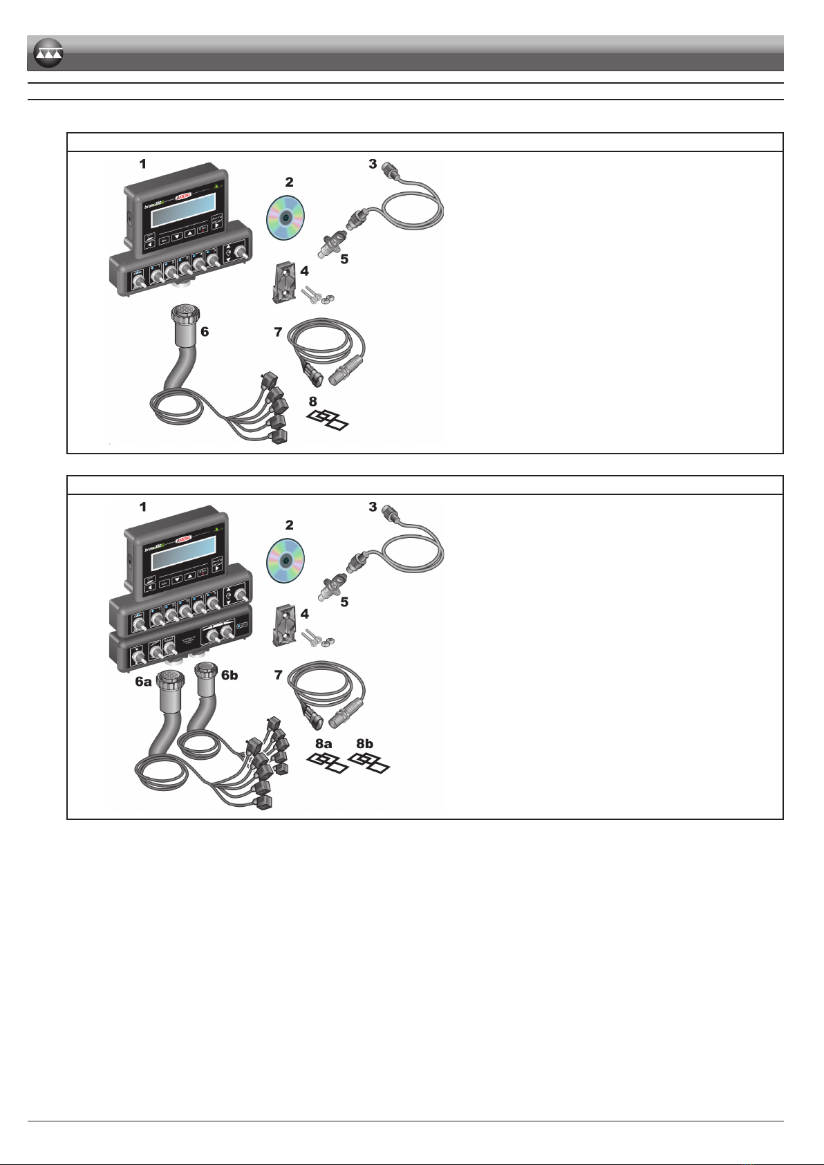
6 Package content .......................................................................6
7 Position on farming machine ..................................................7
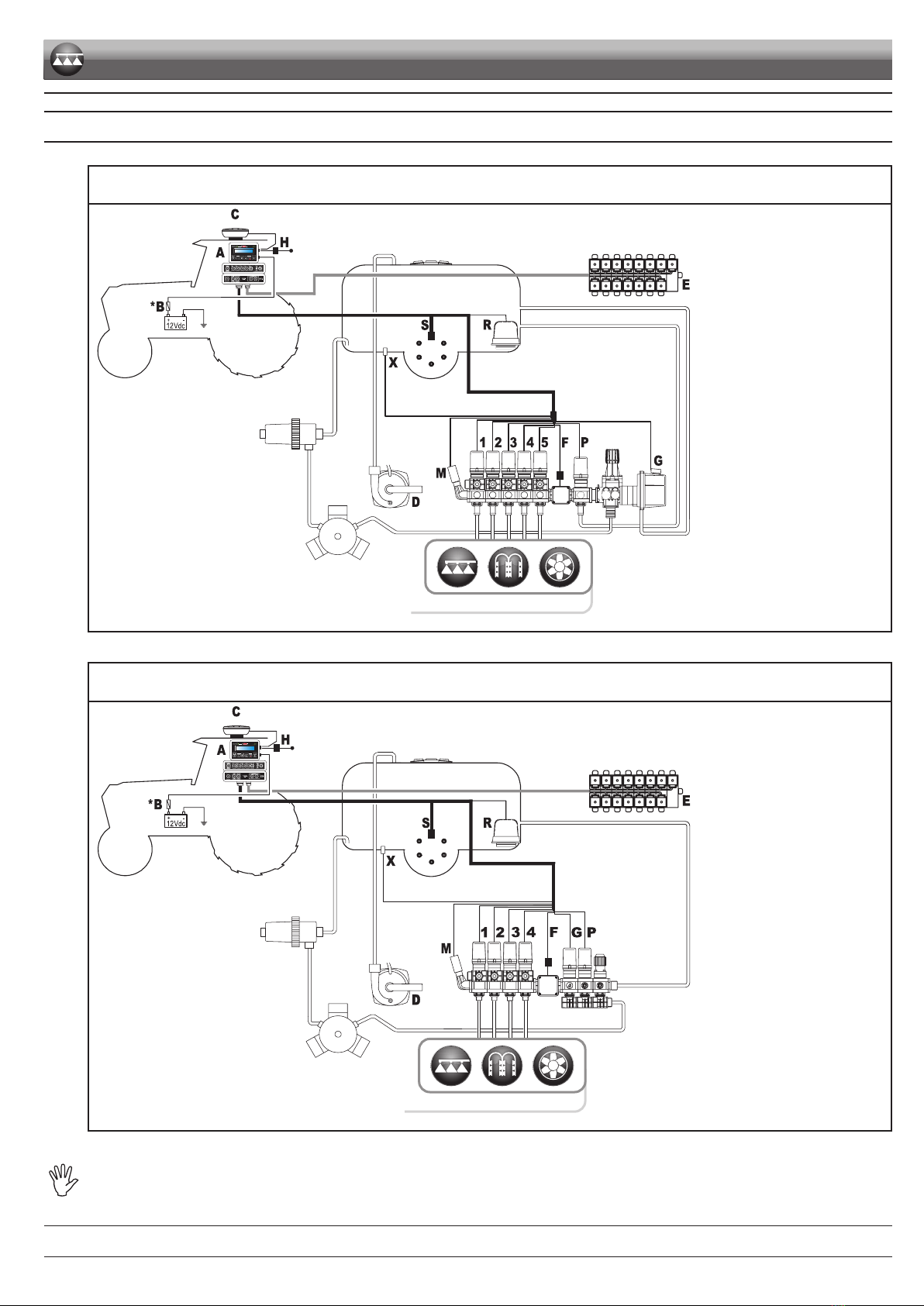
7.1 System recommended composition.................................7
7.2 Computer positioning.......................................................9
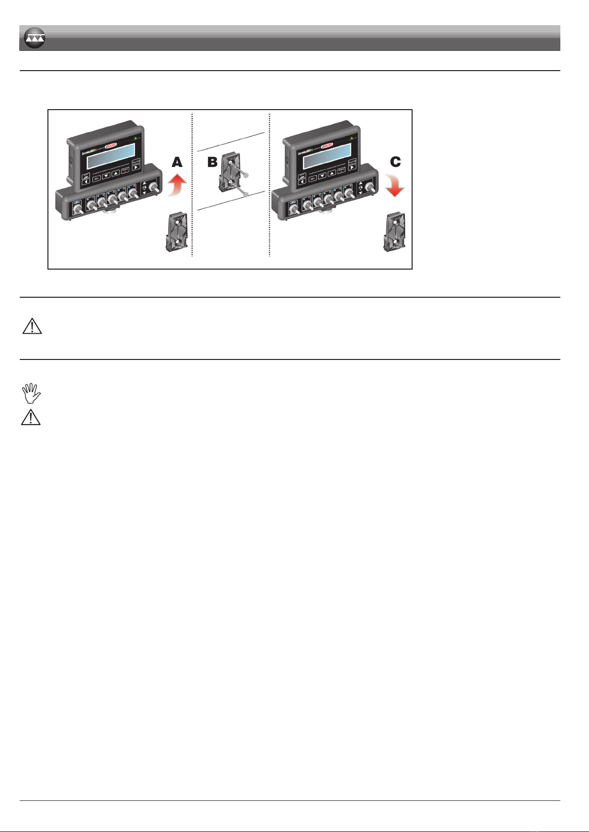
7.3 Bracket fixing .................................................................10
7.4 Control unit position .......................................................10
7.5 Hydraulic unit positioning...............................................10
8 Computer connection to the farming machine....................11
8.1 General precautions for a correct harness position ....... 11
8.2 Power supply connection ...............................................12
9 Harness connection to the control unit, the hydraulic unit
and the available functions....................................................13
9.1 Multicore cable connection ............................................13
9.2 Control unit valve connection.........................................13
9.3 Hydraulic valve connection ............................................14
9.4 Connection of sensors and other available functions....15
9.5 Pendrive.........................................................................15
10 Setup........................................................................................16
10.1 Computer switching on/off..............................................16
10.2 Use of keys for setup .....................................................17
11 Advanced setup ......................................................................18
11.1 Tests and checks before programming ..........................18
11.2 Language.......................................................................19
11.3 Units of measur..............................................................19
11.4 No. of sections ...............................................................19
11.5 Total boom width............................................................19
11.6 Device connect. .............................................................20
11.7 USB log enable..............................................................20
11.8 Speed sensor.................................................................20
11.9 Valves ............................................................................21
11.10 Flowmeter ......................................................................21
11.11 Flowmeter constant........................................................22
11.12 Pressure sensor.............................................................22
11.13 Flow calculation *...........................................................22
11.14 Press. calc. *...................................................................22
11.15 Nozzle qty * ...................................................................22
11.16 Tank source ...................................................................23
11.17 Tank setup .....................................................................23
11.18 Spraying Menu...............................................................24
12 User setting.............................................................................25
12.1 Jobs setup .....................................................................26
12.2 Nozzle data * .................................................................27
12.3 Minimum regulation pressure * ......................................28
12.4 Wheel selection **..........................................................28
12.5 Minimum speed .............................................................28
12.6 Rate correction...............................................................28
12.7 Level correction * ...........................................................29
12.8 Display contrast .............................................................29
12.9 Acoustic signals .............................................................29
12.10 Test device.....................................................................29
12.11 Totalizers........................................................................30
12.12 Settings manag. .............................................................30
13 Use...........................................................................................31
13.1 Display ...........................................................................31
13.2 Controls on computer.....................................................31
13.2.1 Keys to check the computer and the spraying phases ...... 31
13.2.2 Operating switches for control unit valves.......................... 31
13.2.3 Operating switches for hydraulic valves............................. 31
14 Treatment preliminary settings .............................................32
14.1 Selecting the job program (for automatic control only)...32
14.2 Azzeramento dei totalizzatori.........................................32
14.3 Application rate regulation .............................................33
14.3.1 Automatic operation (DEFAULT) ......................................... 33
14.3.2 Manual operation................................................................ 33
14.4 Automatic closure of the main valve ..............................33
14.5 Output menu ..................................................................34
14.5.1 Tank filling ........................................................................... 35
15 Maintenance / diagnostics / repairs ......................................36
15.1 Operation errors.............................................................36
15.2 Troubleshooting..............................................................37
15.3 Cleaning rules................................................................37
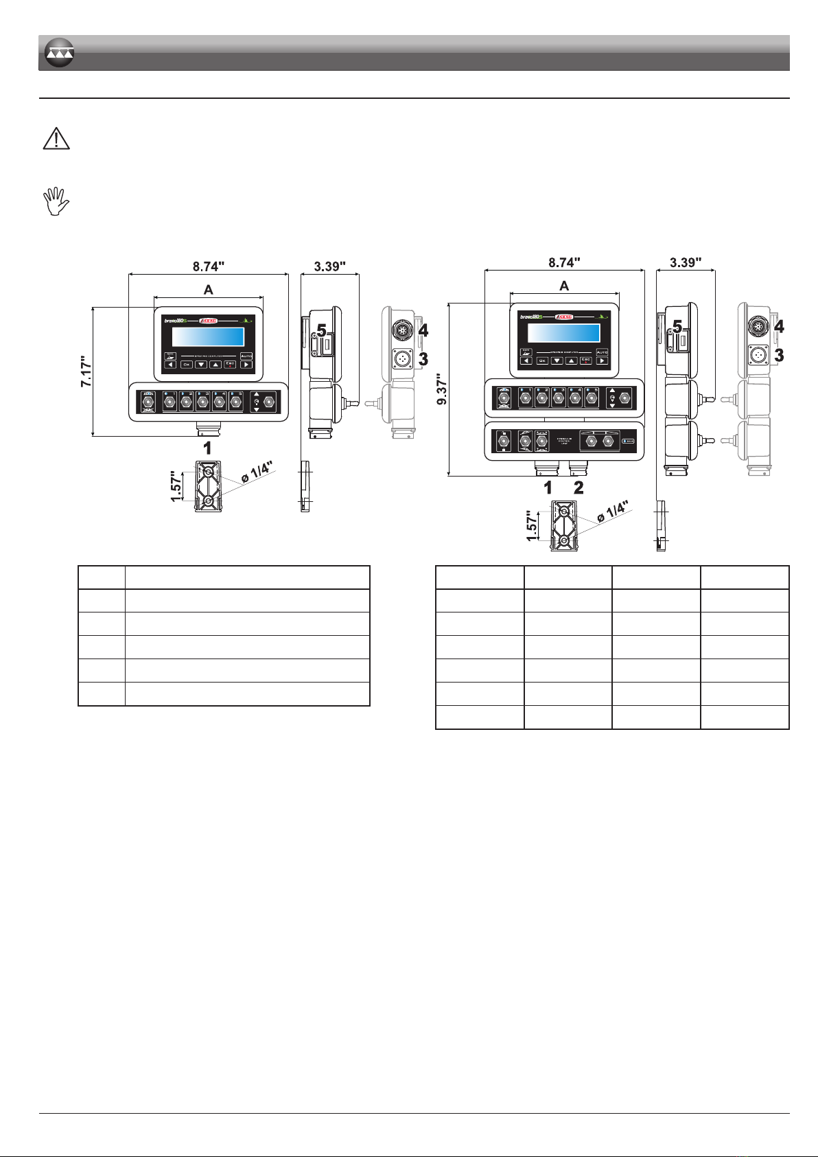
16 Technical data.........................................................................38
16.1 Computer technical data ...............................................39
17 End-of-life disposal ................................................................40
18 Guarantee terms .....................................................................40

4
• MANUAL FOREWORD AND USE
This manual provides instructions to assemble, connect and set the computers of the BRAVO 180S family.
Any other information is provided in specic sheets to be used exclusively by the installer, containing specic information of each computer model.
• MANUAL USE MODES
The section of this manual dedicated to the installation contains information for installers. For this reason we have used technical terms without
providing explanations which would be necessary for end users only.
THE INSTALLATION MUST BE CARRIED OUT BY AUTHORISED AND SKILLED PERSONNEL ONLY. THE MANUFACTURER IS
NOT RESPONSIBLE FOR ANY OPERATION SPECIFIED IN THIS MANUAL CARRIED OUT BY UNAUTHORISED OR UNSKILLED
PERSONNEL.
• LIMITATIONS
The descriptions of the assembly phases refer to a "general" computer, so specic models will not be mentioned, unless a certain installation procedure
concerns exclusively one computer type.
• RESPONSIBILITY
The installer must carry out workmanlike installations and ensure to the end user the perfect operation of the whole system both with ARAG components
only and other brands' components.
ARAG always recommends using its components to install control systems.
The installer will be held responsible for any malfunction if he decides to use other brands' components even without actually changing the system
parts or harness.
The compatibility check with components and accessories of other manufacturers shall be carried out by the installer.
If the computer or the ARAG components installed together with other brands' components get damaged because of what stated above, no direct or
indirect warranty will be provided.
INTRODUCTION

5
INSTALLATION
1 PRODUCT DESCRIPTION
The device you have purchased is a computer which, when connected to a valve or suitable control unit, makes it possible to control all phases of
treatment in agricultural applications directly from the cabin of the farming machine it is installed in.
These computers can be connected to different sensor types.
The computer is directly connected to the system by means of two cables connected to the hydraulic and control unit valves and the sensors. In the
cabin you nd all controls necessary to manage the system ensuring great safety during the job.
The BRAVO 18x computer display allows the operator to constantly monitor all data of the current operations, such as vehicle speed, sprayed uid
quantity, the whole sprayed area and so on.
2 BRAVO DSB
ARAG has designed and manufactured a diagnostics system for Bravo series computers and the systems they may be connected to.
BRAVO DSB (code 467003) provides reliable diagnostics of computer, control unit or the whole system troubleshooting any potential problems
experienced with the BRAVO DSB system.
3 RISKS AND PROTECTIONS BEFORE ASSEMBLY
All installation works must be done with battery disconnected, using suitable tools and any individual protection equipment
deemed necessary.
Use ONLY clean water for treatment tests and simulations: using chemicals during simulated treatment runs
can seriously injure persons in the vicinity.
4 INTENDED USE
This device is designed to work on agricultural machinery for spraying and crop spraying applications.
The machine is designed and built in compliance with UNI EN ISO 14982 standard (Electromagnetic compatibility - Forestry and
farming machines), harmonized with 2014/30/UE Directive.
5 PRECAUTIONS
• Do not aim water jets at the equipment.
• Do not use solvents or fuel to clean the case outer surface.
• Do not clean equipment with direct water jets.
• Comply with the specied power voltage (12 VDC).
• In case of voltaic arc welding, remove connectors from BRAVO and disconnect the power cables.
• Only use ARAG genuine spare parts and accessories.

6
6 PACKAGE CONTENT
The table below indicates the components that you will nd in the BRAVO computer package:
BRAVO 180S COMPUTER
Fi g . 1
Legend:
1 Bravo 180S
2 Instruction manual (DVD-ROM)
3 Power cable
4 Fixing kit
5 Power supply connector
6 Valve and sensor harness
7 Inductive speed sensor
8 Section valve connector seals
BRAVO 180S COMPUTER WITH HYDRAULIC CONTROLS
Fi g . 2
Legend:
1 Bravo 180S
2 Instruction manual (DVD-ROM)
3 Power cable
4 Fixing kit
5 Power supply connector
6a Valve and sensor harness
6b Hydraulic unit harness
7 Inductive speed sensor
8a Section valve connector seals
8b Hydraulic valve connector seals
INSTALLATION

7
7 POSITION ON FARMING MACHINE
7.1 System recommended composition
ASSEMBLY DIAGRAM FOR SPRAYER WITH DIAPHRAGM PUMP
SYSTEM WITH MAIN VALVE
INTENDED APPLICATIONS
Fi g . 3
Legend:
AMonitor
BBattery
CGPS receiver (optional)
DFilling pump
FFlowmeter
HExternal general control /
external speed sensor
XLevel sensor
MPressure sensor
RFoam marker
(crop spraying only)
SSpeed sensor
PControl valve
GMain valve
1÷5 Section valves
EHydraulic unit
ASSEMBLY DIAGRAM FOR SPRAYER WITH DIAPHRAGM PUMP
SYSTEM WITH DRAIN VALVE
INTENDED APPLICATIONS
Fi g . 4
Legend:
AMonitor
BBattery
CGPS receiver (optional)
DFilling pump
FFlowmeter
HExternal general control /
external speed sensor
XLevel sensor
MPressure sensor
RFoam marker
(crop spraying only)
SSpeed sensor
PControl valve
GMain valve
1÷4 Section valves
EHydraulic unit
The computer must be directly connected to the farming machine battery.
* Do not connect the computer to key-operated switch (15/54).
CONTINUES
INSTALLATION

8
ASSEMBLY DIAGRAM FOR SPRAYER WITH CENTRIFUGAL PUMP
INTENDED APPLICATIONS
Fi g . 5
Legend:
AMonitor
BBattery
CGPS receiver (optional)
DFilling pump
FFlowmeter
HExternal general control /
external speed sensor
XLevel sensor
MPressure sensor
RFoam marker
(crop spraying only)
SSpeed sensor
PControl valve
1÷5 Section valves
EHydraulic unit
The computer must be directly connected to the farming machine battery.
* Do not connect the computer to key-operated switch (15/54).
INSTALLATION

9
7.2 Computer positioning
• The BRAVO 180S series computer must be placed in the control cabin of the farming machine. Observe the following precautions:
- Do NOT install the monitor in areas where it would be subjected to excessive vibrations or shocks, to prevent any damage or
accidental use of the control keys;
- Install the device in a visible position within easy reach by hand; bear in mind that the monitor should not obstruct the
operator’s freedom of movement or block his view.
Consider all necessary connections of the computer, the cable length, and make sure there is enough space for connectors and
cables.
An identication symbol is located next to each connector to indicate its function. For any reference to the system conguration
read par. 7.1 System recommended composition.
Fi g . 6
Fi g . 7
ITEM CONNECTION POINTS SECTIONS MASTER PRESSURE WIDTH
A
1Control unit and sensors -- • • 5.98"
2Hydraulic unit 2 • • 5.98"
3Power supply 3 • • 5.98"
4Auxiliary connections 4 • • 8.74"
5USB 5 • • 8.74"
7 • • 10.55"
INSTALLATION

10
7.3 Bracket xing
The monitor must be mounted after having xed the bracket at the desired location (the previous paragraph shows the bracket drilling template).
The bracket must be slid out of the monitor seat (A, Fig. 8) and xed using the supplied screws (B).
Make sure the bracket is securely mounted, t the monitor on it, and push it until it locks in place (C).
Fi g . 8
7.4 Control unit position
The control unit must be xed with the special brackets supplied and tted to the unit, positioning it as shown in the manual provided with the assembly.
MAKE SURE TO FOLLOW ALL THE SAFETY INSTRUCTIONS GIVEN IN THE CONTROL UNIT’S MANUAL.
7.5 Hydraulic unit positioning
The hydraulic unit shall be secured to the machine, making sure it is well protected against the elements and the uid sprayed by the machine.
ARAG IS NOT LIABLE FOR ANY DAMAGE RESULTING FROM THE INSTALLATION BY UNSKILLED PERSONNEL. ANY SYSTEM
DAMAGE CAUSED BY A WRONG INSTALLATION AND/OR CONNECTION AUTOMATICALLY VOIDS THE WARRANTY.
WARNING! DO NOT CONNECT HYDRAULIC UNITS OTHER THAN THE SPECIFIED ONES (SEE ARAG GENERAL CATALOGUE).
ARAG IS NOT LIABLE FOR ANY DAMAGE TO THE PRODUCT, MALFUNCTION ERRORS AND ANY KIND OF RISK IF THE MODULE
IS CONNECTED TO NON ORIGINAL UNITS OR UNITS NOT SUPPLIED BY ARAG.
INSTALLATION

11
8 COMPUTER CONNECTION TO THE FARMING MACHINE
8.1 General precautions for a correct harness position
• Securing the cables:
- secure the harness so that it does not interfere with moving parts;
- route the harnesses so that they cannot be damaged or broken by machine movements or twisting.
• Routing the cables to protect against water inltrations:
- the cable branches must ALWAYS be faced downwards (see gures below).
DIRECT CONNECTION
Fi g . 9
Fi g . 10
• Fitting the cables to the connection points:
- do not force the connectors by pushing too hard or bending them: the contacts may be damaged and computer operation may be compromised.
Use ONLY the cables and accessories indicated in the catalogue, having technical features suitable for the use to be made of
them.
INSTALLATION

12
8.2 Power supply connection
The package includes the power connector (Fig. 1 and Fig. 2 on page 6) to be connected to the farming machine battery;
Fig. 13 shows the drilling template of the power connector.
Connect the power connector to the battery wires using two 0.250" faston connectors, as indicated in Fig. 11 and Fig. 12.
Use the cable provided with the package (Fig. 1 and Fig. 2 on page 6) to connect the computer to the power supply.
Fi g . 11 Fi g . 12
0.20"
= 1.81" =
1.02"
Fi g . 13
WARNING:
To avoid short circuits, do not connect the power cables to battery before the installation is completed.
Before powering up the computer and control unit, make sure the battery voltage is as specied (12 Vdc).
BRAVO 180S is supplied directly by the farming machine battery (12 Vdc): ALWAYS switch on the computer through the monitor, and then remember
to switch it off using the specic key on the control panel.
If BRAVO 180S remains on for a long time with the machine off, the tractor battery could run at: in case of prolonged breaks of
the machine with engine off, make sure the computer is off, too.
The power source must be connected as indicated in Fig. 14: the computer must be connected directly to the farming machine battery. DO NOT
connect the computer to key-operated switch (15/54).
Fi g . 14
WARNING:
• The power circuit shall ALWAYS be protected by a 10 A fuse
like the ones for automotive applications.
• All cables connected to the battery shall have a minimum
cross-section of AWG 14.
To avoid short-circuits, connect the power cable connector only
after completing installation.
• Use cables with suitable terminals ensuring correct connection
of all wires.
INSTALLATION

13
9 HARNESS CONNECTION TO THE CONTROL UNIT, THE HYDRAULIC UNIT
AND THE AVAILABLE FUNCTIONS
• Use only the cables provided with the ARAG computers.
• Take care not to break, pull, tear or cut the cables.
• Use of unsuitable cables not provided by ARAG automatically voids the warranty.
• ARAG is not liable for damages to the equipment, persons or animals caused by failure to observe the above instructions.
9.1 Multicore cable connection
Connect the multicore cable to the monitor (connections 1 and 2 on page 9) and the other cable end to the control unit and the hydraulic unit.
Ensure it is correctly in place and turn the ring nut clockwise until blocking it.
9.2 Control unit valve connection
• Use ARAG valves: use of unsuitable valves not provided by ARAG automatically voids the warranty.
ARAG is not liable for damage to the equipment, persons or animals caused by failure to observe the above instructions.
• All valve connectors must be provided with seals before being connected (Fig. 16).
• Make sure the seals are correctly tted to avoid water inltration when using the control unit.
Connector 1 shall control the valve which in turn is connected to the section 1, and so on with the other valves.
Connect "connector 1" to "valve 1" and then the other connectors with increasing numbers from left to right: section 1 is the furthest from the
machine on the left, looking at the machine from the rear side (Fig. 15).
Section 2 Section 3 Section 4Section 1
Valve 1 Valve 3Valve 2 Valve 4
Section 5
Valve 5
Fig. 15
Fig. 16
Fix the connectors to the relevant valves according to the initials indicated in your assembly general diagram (7.1 System recommended composition):
• Remove the protection cap (1, Fig. 16) from the electric valve.
• Place the seal (2) onto the connector (3), and push the connector fully on (4): be careful not to bend the contacts upon insertion on the valve.
• Tighten the screw (5) fully home.
In case there are more monitor switches than section valves, connect the cables as indicated in the table:
SECTION VALVE NO. SWITCHES TO BE USED CABLES TO BE CONNECTED
TO THE SECTION VALVES
2 2 - 4 2 - 4
3 2 - 3 - 4 2 - 3 - 4
4 1 - 2 - 4 - 5 1 - 2 - 4 - 5
INSTALLATION

14
9.3 Hydraulic valve connection
Fi g . 17
Bravo 180S can control up to 7 hydraulic functions through double-acting valves.
Fix the connectors to the relevant valves according to the initials indicated in your assembly general diagram
(7.1 System recommended composition).
• Position seal (1) onto connector (2), then connect the latter pressing it fully home (3):
during this operation, take special care not to bend valve electric contacts.
• Insert screw inside connector, and screw it (4) until it is tightened.
The function of each switch on the hydraulic function control panel is described below.
• Connect the connector marked with "DD" to the pilot valve, and then the other connectors, as specied on the table:
CONTROL MOVEMENT CONNECTOR
Section movement / AUX switch opening
1 - 4
Opening 1 ÷ 4 A
Closing 1 ÷ 4 C
Boom height
Opening AA
Closing AC
Boom locking
Opening BA
Closing BC
Boom leveling
Opening CA
Closing CC
INSTALLATION

15
9.4 Connection of sensors and other available functions
Fix the connectors to the relevant functions according to the initials indicated in your assembly general diagram (par. 7. 1 ).
Harness cables are marked with a symbol denoting their functions: please see the table for correct harness connection.
Use ARAG sensors: use of unsuitable sensors not provided by ARAG automatically voids the warranty.
ARAG is not liable for damage to the equipment, persons or animals caused by failure to observe the above instructions.
ITEM CONNECTION
FFlowmeter
MPressure sensor
RFoam marker
SSpeed sensor
XLevel sensor
PControl valve
GMain valve
- The products are supplied with the sensor installation instructions.
- Connection of:
• owmeter;
• pressure sensor;
• level sensor
• foam marker.
All ARAG sensors use the same type of connector. Connect the sensor connector to the relevant harness; make sure it is correctly tted and push it
until locking it.
Fig. 18 Fig. 19
9.5 Pen drive
The pen drive may be used to exchange data with the BRAVO 180S computer.
Before using it make sure the pen drive is not protected.
All pen drives with up to 8 GB memory are compatible.
INSTALLATION

16
Par.10.2
Shifting
of the cursor
Quits the menu or
the data change
Conrms access to menu
or data change
Menu item scrolling or
Data increase/decrease
10 SETUP
10.1 Computer switching on/off
• Ordinary switching on
Bravo 180S
SPR Ver 1.8.0
Software version
----- Menu -----
--- Spraying ---
Fig. 20
Keep key ESC pressed until switching on the display: after the software version, Bravo 180S displays the job screen (Fig. 20).
• Switching on to activate the advanced setup
Bravo 180S
SPR Ver 1.8.0
----- Menu -----
--- Advanced ---
Software version Job screen
Fig. 21
Contemporaneously press the key sequence until switching on the Bravo. Release key ESC keeping pressed the arrow keys until the display shows the
Advanced menu (Fig. 21).
• Switching off
Power OFF...
Release ESC key
Fig. 22
Keep key ESC pressed until the display shows the message Power OFF... Release ESC KEY
Release the key and wait for the saving process to complete (Fig. 22); after a few seconds the computer turns off.
During switching off do NOT press any other key and do NOT disconnect the power supply until Bravo 180S turns off.
WARNING: ALWAYS use the special key to switch off the computer; otherwise ALL data concerning the spraying and the
programming will be lost.
SETUP

17
Par.10.2
Shifting
of the cursor
Quits the menu or
the data change
Conrms access to menu
or data change
Menu item scrolling or
Data increase/decrease
10.2 Use of keys for setup
Language
English
2
Units of measur.
US
No. of sections
5
1
Fig. 23
1Press the arrow keys in succession to move across the menu items.
(next item, previous item); the selected item will be displayed (Fig. 23).
2Press
OK to access the menu: during set-up, a cursor blinks on the display
(Fig. 24).
DATA SELECTION
Language
Englis
4a
Italian
3a
Fig. 24
When it is about a simple selection of data, BRAVO 180S displays the active value (Fig. 24):
3a Press the arrow keys in succession to select another value.
(next value, previous value); the selected value will be displayed.
4a Conrm with OK.
Quick scrolling: keep one of the arrow keys pressed.
Exit without conrming the change: press ESC.
ACCESS TO A SUBMENU
Speed sensor
. . .
Wheel 1/3
19.68 in./pls
Wheel 2/3
Disabled
4b
3b
5b
Fig. 25
If there is a sub-menu, BRAVO 180S displays three dots ". . ." (Fig. 25):
3b Press OK to access to the submenu.
4b Press repeatedly to toggle from one item to another of the submenu
(next item, previous item); the selected item will be displayed.
5b Click OK to access the selected item.
Quick scrolling: keep one of the arrow keys pressed.
Press ESC to go back to the previous level of the menu.
ENTERING A NUMERICAL VALUE
Wheel 1/3
19. 8 in./pls
8
6
7
Fig. 26
6Press in succession to move the cursor across the digits
(shifting to the LEFT, shifting to the RIGHT).
7Press in succession to change the value selected by the cursor.
(increase, decrease).
8Press OK to conrm the data.
Quick increase / decrease: keep one of the arrow keys pressed.
Exit without conrming the change: press ESC.
Below is a summary of key functions during setup.
SETUP

18
Par.10.2
Shifting
of the cursor
Quits the menu or
the data change
Conrms access to menu
or data change
Menu item scrolling or
Data increase/decrease
11 ADVANCED SETUP
The computer can be set-up with the all data required to ensure a correct distribution of the treatment product.
This operation must be done once only, when installing the computer.
11.1 Tests and checks before programming
Before proceeding with computer programming check the correct installation of all components (control unit and sensors), the
connection to the power supply and the connection to the components (general control unit and sensors).
Failure to correctly connect system components or to use specied components might damage the device or its components.
ACCESS TO ADVANCED MENU
Fig. 27
Advanced setup (with computer off)
• Contemporaneously press the key sequence until switching on the Bravo.
• Release the key ESC by keeping the arrow keys pressed until the menu is displayed.
For a correct use of the keys during setting, refer to par. 10.2.
The minimum and maximum values relevant to the data that can be set are indicated
in chap. 16.
ADVANCED MENU - STRUCTURE
* MENU VISIBLE
ONLY WITH
SPECIFIC SETTINGS
Par.11.2
Par.11.3
Par.11.4
Par.11.5
Par.11.6
Par.11.7
Par.11.8
Par.11.9
Par.11.12
Par.11.10
Par.11.13
Par.11.14
Par.11.15
Par.11.16
Par.11.17
Par.11.18
Par.11.11
Fig. 28
The screens indicated in the following paragraphs refer to setup key-points only;
The display could change when pressing the keys described in the text.
When setting the data, the relevant value blinks on the display.
ADVANCED SETUP

19
Par.10.2
Shifting
of the cursor
Quits the menu or
the data change
Conrms access to menu
or data change
Menu item scrolling or
Data increase/decrease
11.2 Language
Language
English
Fig. 29
Set the language of Bravo 180S, among those available.
>Italian, English, Spanish, Portuguese, French, German, Polish, Croatian, Hungarian, Greek, Russian, Turkish,
Czech.
11.3 Units of measur.
Units of measur.
US
Fig. 30
Set the units of measurement used for Bravo 180S.
>EU (l/h, km/h, bar)
US (GPA, mil/h, PSI)
US TURF (applied volume = gal / 1000 square feet, mil/h, PSI)
11.4 No. of sections
No. of sections
5
Fig. 31
Set the number of installed section valves.
11.5 Total boom width
This parameter represents the nozzle actual spraying range on the ground: for example, by positioning 8nozzles at a distance of 19.69" one from the
other, the boom section width to be set is 13.1 ft.
The displayed value (Fig. 32) represents the sum of the section width values, therefore to change the parameter it is necessary to set the width of
each boom section: the sum of the width values will be re-calculated automatically.
1After selecting the menu Total boom width, press OK to gain access to the sub-menu to select / modify the single sections.
2Use the keys to scroll the sections in the sub-menu Section until viewing the section to be modied: the section number is indicated on the top
right side of the display, whereas the rst line shows the current value (Fig. 33).
3Press OK to conrm the access to the modication function.
4Enter the section width value and repeat the setting procedure for each section.
Total boom width
65.6 ft
1
Fig. 32
Total boom width : 65.6ft
Section 1/5
13.1 ft
3
2
2
Section number
Fig. 33
Valve 1
Section 1 : 13.1 ft
Section 2/5
13. ft
Fig. 34
Valve 2
Section 2 : 13.1 ft
ADVANCED SETUP

20
Par.10.2
Shifting
of the cursor
Quits the menu or
the data change
Conrms access to menu
or data change
Menu item scrolling or
Data increase/decrease
11.6 Device connect.
Device connect.
External device
Fig. 35
Enable / disable any connection to an external.
>Ext. device
Serial LOG
None
The Ext. device setup enables Bravo 180S to receive the spraying data of the variable application rate from
a connected device (e.g.: DELTA 80), the serial LOG item transmits, in turn, to the serial port a string of data
relevant to the job to be sent via cable or to be transmitted to an equipment used.
11.7 USB log enable
Abilit. log USB
No
Fig. 36
Enable / disable the LOG le export to a USB pendrive (note: the pendrive must be connected to the USB port of
Bravo 180S)
>No
Yes
LOG le string example:
Device,FwVersion,SwType,GPSQ,Date,Time,Lat,Lon,MUnit,Speed,BoomWidth,CoveredArea,TargetRate,ApplRate,Flow,Pr
ess,SprQnty,TankLevel,Sections,Sect1Width,Sect2Width,Sect3Width,Sect4Width,Sect5Width,ActNozzle,SelectedJob
B180S,1.8.0,S,,,00:00:31,,,0,0.0,8.00,0.000,100,0,0.0,,0,1000,11000,4.00,4.00,4.00,4.00,4.00,,J1
B180S,1.8.0,S,,,00:00:33,,,0,0.0,12.00,0.000,100,0,0.0,,0,1000,11100,4.00,4.00,4.00,4.00,4.00,,J1
....
11.8 Speed sensor
Speed sensor
. . .
Fig. 37
In this menu carry out all settings to calculate the speed.
Usually the computer calculates the information concerning the speed thanks to pulses received by the sensor
installed on the wheel.
If a GPS receiver is directly connected to the Bravo 180S, this menu allows selecting the receiver as alternative
source to the wheel sensor, and so to receive in real time the speed data provided by the GPS.
After selecting the menu Speed sensor, press OK to access the sub-menus.
>Wheel
This parameter is used by the BRAVO 180S computer to calculate the vehicle driving speed and, according to this, the instantaneous application rate.
The wheel constant relates to the type of wheel being used and the number of detection points of the sensor installed on it. BRAVO 180S can save 3 different wheel
constants.
In case of replacement of the wheel featuring the detection points of the speed sensors, the wheel constant can change.
In this case it is necessary to set the parameter again.
1Select the wheel type (3 types available).
2Press OK. The constant can be entered with two different procedures (Manual setup or Automatic calc.), described below.
3Select the desired procedure and press OK to enter the constant.
Wheel 1/3
19.68 in./pls
2
1
1
Type of wheel
Fig. 38
Wheel constant
Automatic calc.
Wheel constant
Manual setup
3
Fig. 39
4a Manual setup Allows to enter the wheel constant value calculated with the suitable formula.
Wheel 1/3
19.68 in./pls
Fig. 40
Take measurements with tyres at the
operating pressure.
Kwheel = distance traveled (inches)
no. of detection points x wheel rpm
<distance traveled> distance expressed in cm covered by the wheel along measurement travel.
<no. of measurement points> number of measurement points
(e.g. magnets, bolts, etc.), mounted on wheel.
<no. of wheel revolutions> number of wheel revolutions required to travel measurement distance.
The wheel constant can be calculated with a good approximation by detecting the distance traveled by the wheel with
the speed sensor.
(The longer the distance traveled, the more accurate wheel constant calculation).
4b Automatic calc. BRAVO 180S can automatically calculate the wheel constant using the number of pulses sent by the speed sensor
when driving on a 300 feet (US - US TURF) straight path.
ADVANCED SETUP
Table of contents
Other ARAG Farm Equipment manuals
Popular Farm Equipment manuals by other brands

Segway
Segway NINEBOT ONE S2 user manual

Spudnik
Spudnik 990 Owner/Operator & Parts Manual

Farmi Forest Corporation
Farmi Forest Corporation VALBY HF 160 OPERATION, MAINTENANCE AND SPARE PARTS MANUAL

horsch
horsch LEEB 12 TD operating instructions

MacDon
MacDon C Series Unloading and assembly instructions

MacDon
MacDon NEW HOLLAND D2 Series Unloading and assembly instructions