Out-of-Lock Relay Connect the three wires – normally open (NO), normally closed (NC)
and common (COM) – to the SPDT relay contact terminals. “Normally” refers to the relay
condition with the clock powered off.
RS232 ports Every Model 1095A/C has two RS232 serial ports: COM 1 and COM 2.
Connect a null-modem serial cable between the computer and the clock. The Programming
Port at J8 provides a convenient point to initially configure the clock. Use the phone cable
and RJ-11 to DB9 adapter to connect between J8 and the computer.
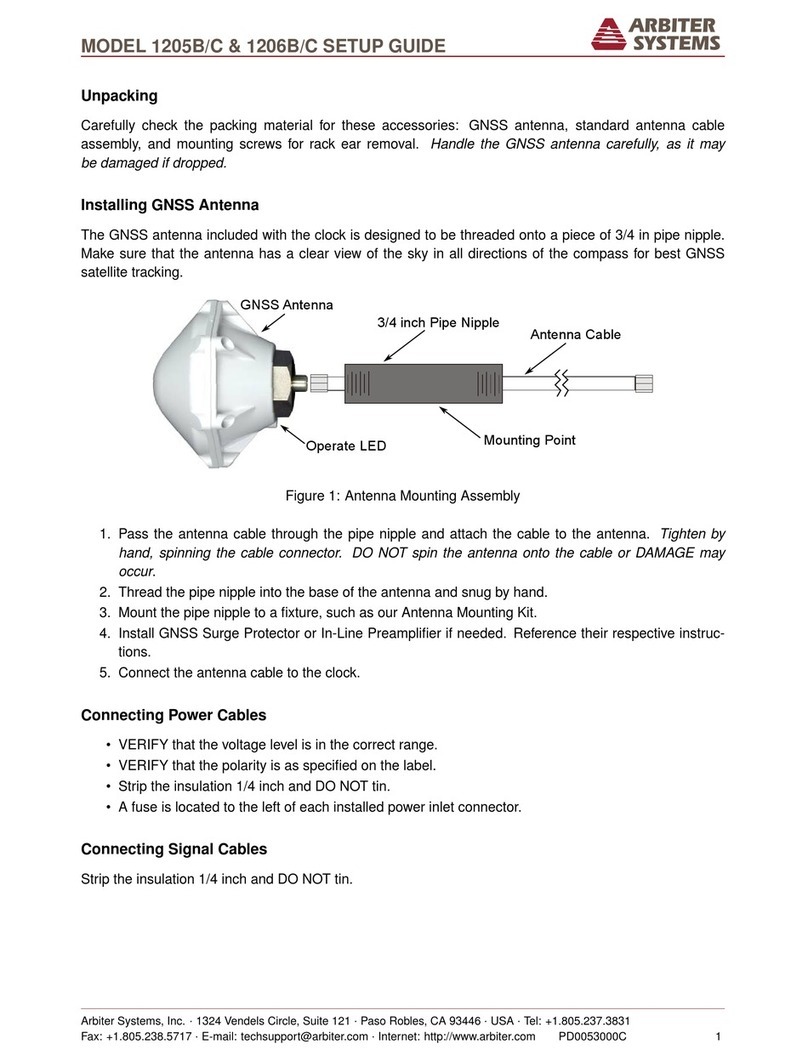
Event Input The Model 1095A/C has one dedicated BNC event input. There are three
input voltage ranges: 5 Vdc to 12 Vdc, 24 Vdc to 48 Vdc, and 120 Vdc to 240 Vdc. Use the
separate terminals to select the input voltage range.
Energizing the Clock
Before connecting voltages to the clock, make sure to read the power inlet label to verify the correct
voltage. The Model 1095A/C accepts an unregulated input between 9 Vdc and 30 Vdc, at 2 W
max. Make sure that the voltage you are connecting is in the correct range supplied on the label.
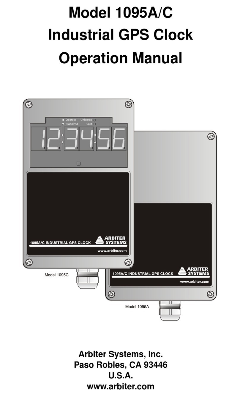
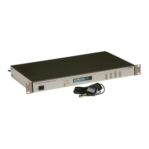
Model 1095A Startup
The green Operate LED and the red Unlocked LED should illuminate, when power is first applied
to the Model 1095A. After a short time of tracking satellites, the Unlocked LED should go out.
After a few minutes of operation while being locked to the GPS, the green Stabilized LED should
light up.
These indications will only be visible with the opaque clock cover removed. With a transparent
(smoked) cover they are visible with the cover in place. Lock and stabilization times above depend
greatly on satellite reception, and are under fairly ideal circumstances1.
Model 1095C Startup
When inlet power is first applied to the Model 1095C, you should see the green Operate and the
red Unlocked LED light up, and the large LED display should produce six dashes then zeros. After
a short time of tracking satellites, the Unlocked LED should go out and the time display will begin
counting. After a few minutes of operation, while being locked to the GNSS, the green Stabilized
LED should light up and the Model 1095C should display the correct time.
Configuring the Clock Settings
Every Model 1095A/C is shipped from the factory with default settings, which can be changed
using the 1095 Utility software through one of the serial ports. This section discusses configuring
the clock using the front panel in which two common configuration examples are given. For a
complete configuration of the clock, download the pdf version of the manual, or order a printed
version from Arbiter Systems.
Configuring Time and IRIG-B Settings
Two of the most common and important settings to configure on a clock are the Time and IRIG-B.
Time needs to be set up for a specific locale, and IRIG-B uses time zone settings in the time code.
1Clock, or antenna, should be mounted with a clear view of the sky from 10 degrees above the horizon to directly
overhead for all points of the compass.
3
