ARC MEST-1701 User manual

1
Issue date: 05/02/2020
MINI ENTRY SENSOR
MEST-1701
CONTENTS
1. Overview and features Page 2.
2. Diagrams Page 3.
3. Battery Page 4.
4. Mounting on surface Page 7.
5. Pairing / Un-pairing device Page 11.
6. Delay Off timer setup Page 14.
7. Operation Page 17.
8. Specifications Page 19.

2
Issue date: 05/02/2020
1.Overview and features
Miniature entry sensor designed to detect the opening of a door or window.
One half of the assembly set on a window or door frame and the other attach to
the window or door itself. When the sensor is separated from each other it
automatically switch On / Off lights or triggers a security alert.
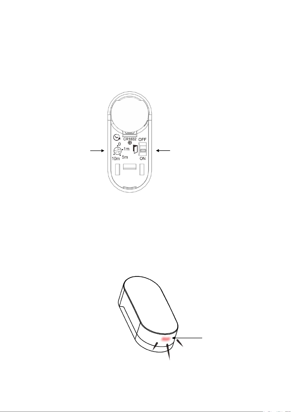
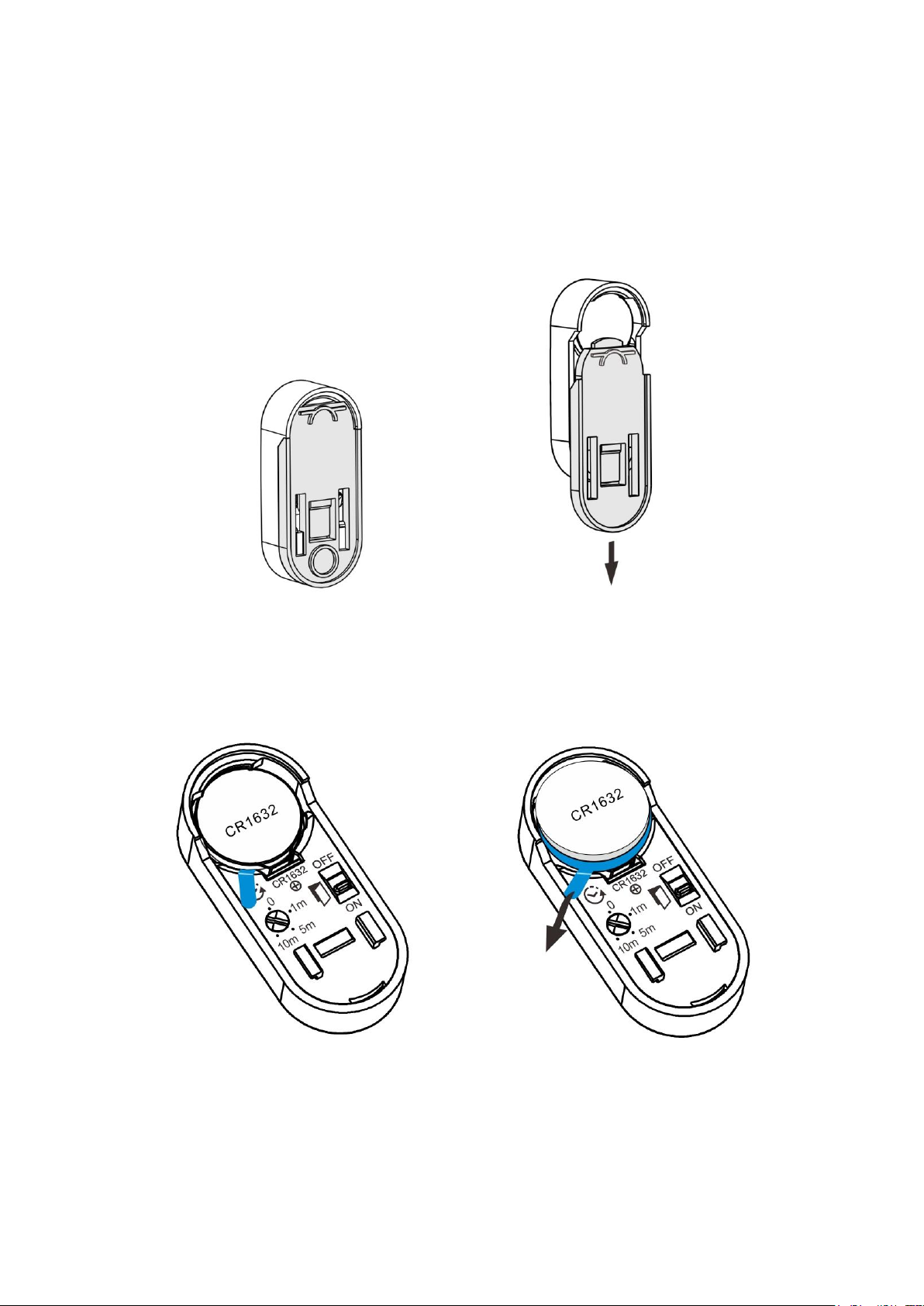
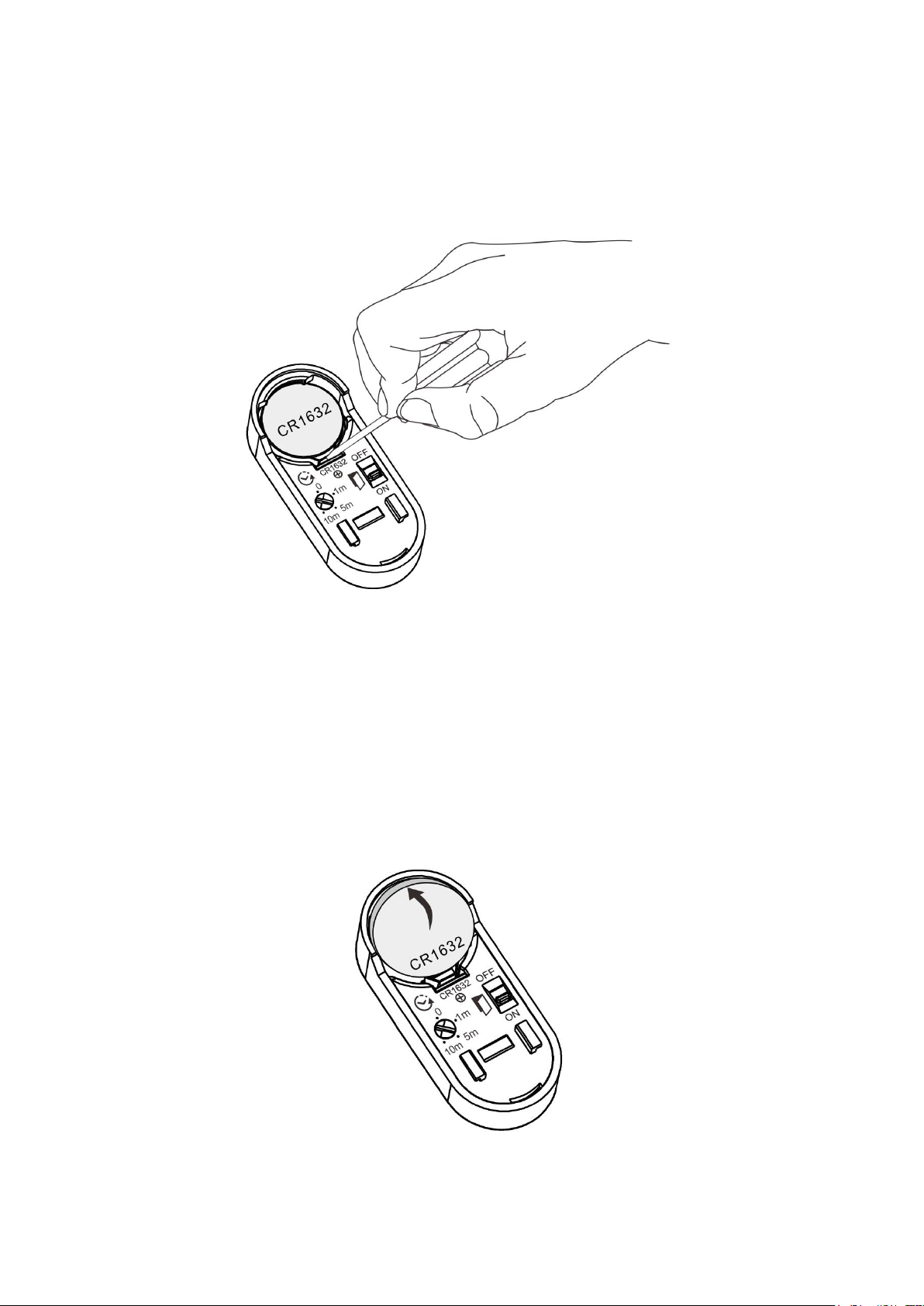
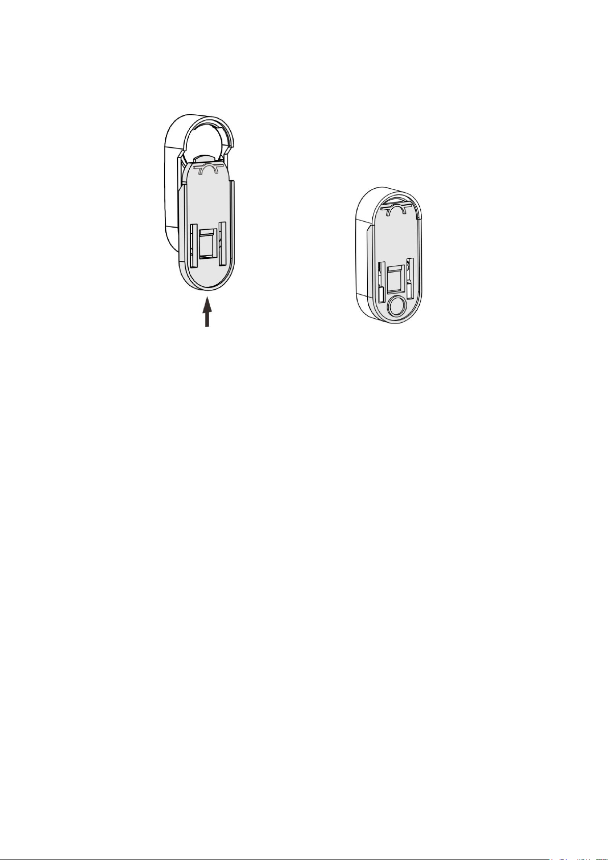
3V CR1632 battery operation capable of 3-year battery life and built in battery
low indicator.
Main features;
•Compatible to L and M series.
•Option to manually select ON/OFF or OFF/ON function with the magnet
and sensor separated or closed.
•Extra feature of Delay off timer (0 / 1M / 5M / 10M).
•Easy mounting with screws or use adhesive tape on flat surface.
•Suitable for windows, door, closet, wine storage room etc…
Precautions:
Not compatible to dimmer receiver devices.
Always mount indoors as the entry sensor is not waterproof.
Do not place the sensor close to magnetic or electromagnetic fields.
OVERVIEW AND FEATURES

3
Issue date: 05/02/2020
2.Diagrams.
Notes for the diagrams:
Sensor
When you select between function switch ON and OFF, the LED on sensor will
indicate as:
Position ON: LED flash once
Position OFF: LED flash twice
Sensor
DIAGRAMS
Delay off timer
Function Switch
Position OFF
Separate Sensor trigger OFF signal
Close Sensor trigger ON signal
Position ON
Separate Sensor trigger ON signal
Close Sensor trigger OFF signal
LED Indicator

4
Issue date: 05/02/2020
3.Battery
Red LED will flash once every 4 seconds to indicate the battery is low.
1. With the sensor back side facing up, gently slide down the back cabinet.
2. Remove battery insulation strip. (First time use only)
BATTERY

5
Issue date: 05/02/2020
3. Or replace new battery with a slot screwdriver and push down the metal
spring then remove battery.
4. Replace with a new 3V CR1632 battery.
Gently tilt battery at an angle towards the metal spring and with some force
push down the battery making sure the positive symbol is facing upwards.
BATTERY

6
Issue date: 05/02/2020
5. Slide battery cabinet upwards to complete.
LITHIUM BATTERY CAUTION:
Risk of Explosion if battery is replaced by an incorrect type. Dispose of used
batteries according to the environment protection rules.
BATTERY

7
Issue date: 05/02/2020
4.Mounting On Surface
Entry sensor has 2 ways of mounting onto flat surface and magnet has no
position restrictions. It can be either on the left or right of the sensor or up and
down depending where the entry sensor is used.
However, we recommend mounting the sensor on the frame to protect the
electronics from heavy vibrations.
Magnet on the left Magnet on the right
Mounting on sliding door or window
MOUNTING ON SURFACE

8
Issue date: 05/02/2020
Position of the sensor and the magnet.
The sensor and the magnet should be mounted on the door or window no
further than 5mm away between each other.
2 methods of mounting.
Method 1.
With 3M double sided adhesive tape enclosed in the accessory pack.
Method 2.
Mounting with 4 screws enclosed in the accessory pack:
1. Remove battery cabinet from sensor.
MOUNTING ON SURFACE

9
Issue date: 05/02/2020
2. Remove magnet cover.
Make sure the arrow is facing down and using a little force push downwards
and lift up the magnet cover.
3. With both the arrows facing up, mount battery cabinet and magnet cover on
flat surface with cross head screwdriver.
4. Slide downwards the sensor battery cabinet.
MOUNTING ON SURFACE

10
Issue date: 05/02/2020
5. On a slight angle tilt the magnet and push down onto the cover making sure
a ‘click’ sound is heard.
6. To remove sensor and magnet after mounting, simply push upwards with a
little force.
MOUNTING ON SURFACE

11
Issue date: 05/02/2020
5.Pairing / Un-pairing Device
PAIRING /UN-PAIRING
Refer to the relevant receiver operation manual that you wish to control for
detailed pairing / un-pairing procedure.
With the receiver that you intent to use, enter into “Learning Mode”
2 Methods of pairing / un-pairing:
Method 1.
To Pair:
1. With the receiver enter into “Learning Mode”
2. On sensor, delay timer must be positon in ‘0’ minute and function switch to
“ON’ position. (LED on module will flash once)
3. Sensor will then trigger to pair receiver device.
Un-Pair:
1. With the receiver enter into “Learning Mode”
2. On sensor, delay timer must be position in ‘0’ minute and function switch to
“OFF’ position. (LED on module will flash twice)
3. Sensor will send trigger to un-pair receiver device.
PAIRING / UN-PARING DEVICE

12
Issue date: 05/02/2020
Method 2.
Function switch to ON position. (LED on module will flash once)
Delay timer must be position in ‘0’ minute.
To Pair:
Separate magnet and sensor to trigger ‘ON’ signal.
To Un-Pair:
Close magnet and sensor to trigger ‘OFF’ signal.
PAIRING / UN-PARING DEVICE

13
Issue date: 05/02/2020
Function switch to OFF position. (LED on module will flash twice)
To Pair:
Close magnet and sensor to trigger ‘ON’ signal.
To Un-Pair:
Separate magnet and sensor to trigger ‘OFF’ signal.
PAIRING / UN-PARING DEVICE

14
Issue date: 05/02/2020
6.Delay Off Timer Setup
You may choose the entry sensor to operate normally as an ON/OFF trigger or
have the extra benefit to set up delay off timer.
Factory pre-setting will be at ‘0’ minute position.
Set up delay off timer:
•There are 4 timer selections, 0 minute –1 minute –5 minutes –10 minutes
•Adjust rotary switch clockwise to the minutes that you wish to setup.
•If you set at ‘0’ minute, the entry sensor will immediately trigger receiver
device when magnetic sensor is separated or closed.
•If you set at ‘1’ minute / 5 minutes, / 10 minutes the entry sensor will
immediately trigger receiver device then delay timer will start to countdown
until it reaches 0 minute then sends signal to the receiver device.
DELAY OFF TIMER SETUP

15
Issue date: 05/02/2020
Timer operation to ‘ON’ operation. (LED on module will flash once)
1. Separate magnetic sensor will trigger ON signal to receiver device and
timer will start to count down, once it reaches 0 minute the sensor will
send OFF signal to the receiver device.
2. During timer countdown if you close the magnetic sensor it will not turn
OFF the receiver device, the timer will still countdown until it reaches 0
minuet then sends OFF signal to the receiver device.
3. Or during the timer countdown, if you separate magnetic sensor again
then this will extend the timer further more.
For example:
Function switch in position ‘ON’ and timer set under 5 minutes.
1. When you open the door the sensor triggers ON signal to the receiver
device and 5 minutes timer starts to countdown.
2. During the countdown say around 2 minutes the door is opened again,
the sensor will trigger receiver again which means the timer will extend
another 5 minutes on top of the remainder 3 minutes.
3. So after 8 minutes the receiver device will turn OFF.
DELAY OFF TIMER SETUP

16
Issue date: 05/02/2020
Timer operation to ‘OFF’position. (LED on module will flash twice)
1. Close magnetic sensor will trigger ON signal to receiver device and timer
will start to count down, once it reaches 0 minute the sensor will send
OFF signal to the receiver device.
2. During timer countdown if you separate magnetic sensor it will not turn
OFF the receiver device, the timer will still countdown until it reaches 0
minute then sends OFF signal to the receiver device.
3. Or during the timer countdown, if you close the magnetic sensor again
then this will extend the timer further more.
For example:
Function switch in position ‘OFF’ and timer set under 1 minute.
1. When you close the door the sensor triggers ON signal to the receiver
device and 1 minute timer starts to countdown.
2. During the countdown say around 30 seconds the door is opened again,
the sensor will trigger receiver again which means the timer will extend
another 1 minute on top of the remainder 30 seconds.
3. So after 1 minute and 30 seconds the receiver device will turn OFF.
DELAY OFF TIMER SETUP

17
Issue date: 05/02/2020
7.Operation
Function switch to ON position.
Trigger ON:
Separate magnet and sensor to trigger ‘ON’ signal.
Trigger OFF:
Close magnet and sensor to trigger ‘OFF’ signal
OPERATION

18
Issue date: 05/02/2020
Function switch to OFF position.
Trigger ON:
Close magnet and sensor to trigger ‘ON’ signal.
Trigger OFF:
Separate magnet and sensor to trigger ‘OFF’ signal.
OPERATION

19
Issue date: 05/02/2020
8.Specifications
Battery: 3V CR1632 Lithium Cell Battery
Radio Frequency: 433.92MHz
Power consumption: 1W
Environment Temperature: 0-50 ºC
Range: Up to 50 m indoors (Depends on building
materials)
In accordance with: Low Voltage Directive 2014/35/EU
RED Directive 2014/53/EU
CE Certification: The CE marked affixed to this product confirms
Its complaisance with the European Directives
Which apply to the product and in particular its
compliance with the harmonizes standards and
specifications.
Dimension
Sensor: 20 x 45.8 x 12 mm
Magnet: 12 x 32 x 11.5 mm
Weight: 30 g
Accessory pack enclosed: 2pcs 3M double sided adhesive tape.
4pcs screws.
Note: Actual battery life may vary with the product settings, operation environment and usage.
SPECIFICATION
Table of contents
Other ARC Accessories manuals
Popular Accessories manuals by other brands

Honeywell
Honeywell RPW111A Mounting instruction

IDROBASE
IDROBASE Adi Use and maintenance manual

Keith
Keith RUNNING FLOOR II DX Owner's and operator's manual

elsner elektronik
elsner elektronik Sewi KNX L Installation and adjustment

Calex
Calex PyroUSB PUA8 Connecting and configuring

Omron
Omron fh series Hardware manual