OPTIMA32 10
This appliance is designed to be attached to two 3” (76 mm) dia (co-linear) aluminum flex liners
running the full length of the masonry chimney or the flue of a factory built fireplace connecting
the inlet of the appliance to the inlet of the termination cap and the outlet of the appliance to
the outlet of the termination cap (DO NOT MIX-UP THESE CONNECTIONS). The flue must be
a minimum length of 8’ (2.44 m) and up to a maximum length of 25’ (7.62 m). Periodically
(every 12 months) check that the venting system is not restricted or blocked. Masonry
chimneys may take various turns which the flex liner will accommodate, however keep the
liner as straight as possible avoiding unnecessary bends.
Only use the approved vertical termination caps with this appliance
Archgard part number TK-32
“Dura-vent” part # 980 (cap), 923GK (adaptor with flashing) or 991 (high wind cap)
Periodically check that the venting system is not restricted or blocked (every 12 months)
WARNING: Operation of this heater when not connected to a properly installed and
maintained venting system can result in carbon monoxide (CO) poisoning and possible
death. The appliance must not be connected to a chimney flue serving a separate solid
fuel burning appliance.
This cap must be sealed to the liner with the high temperature sealant and hose clamps
fasteners provided with the unit. The liners must form a complete connection from the
appliance flue collars to the termination cap.
If you are using the “Dura-vent “ vertical termination cap follow the instructions provided with
these components.
CAUTION: To ensure that the venting path is not accidentally obstructed, or punctured
the damper of the host fireplace must be permanently disabled. By either complete
removal of the damper or welding it in it’s “open” position. Temporarily disabling the
damper with braces, wedges, brackets, etc., is not allowed.
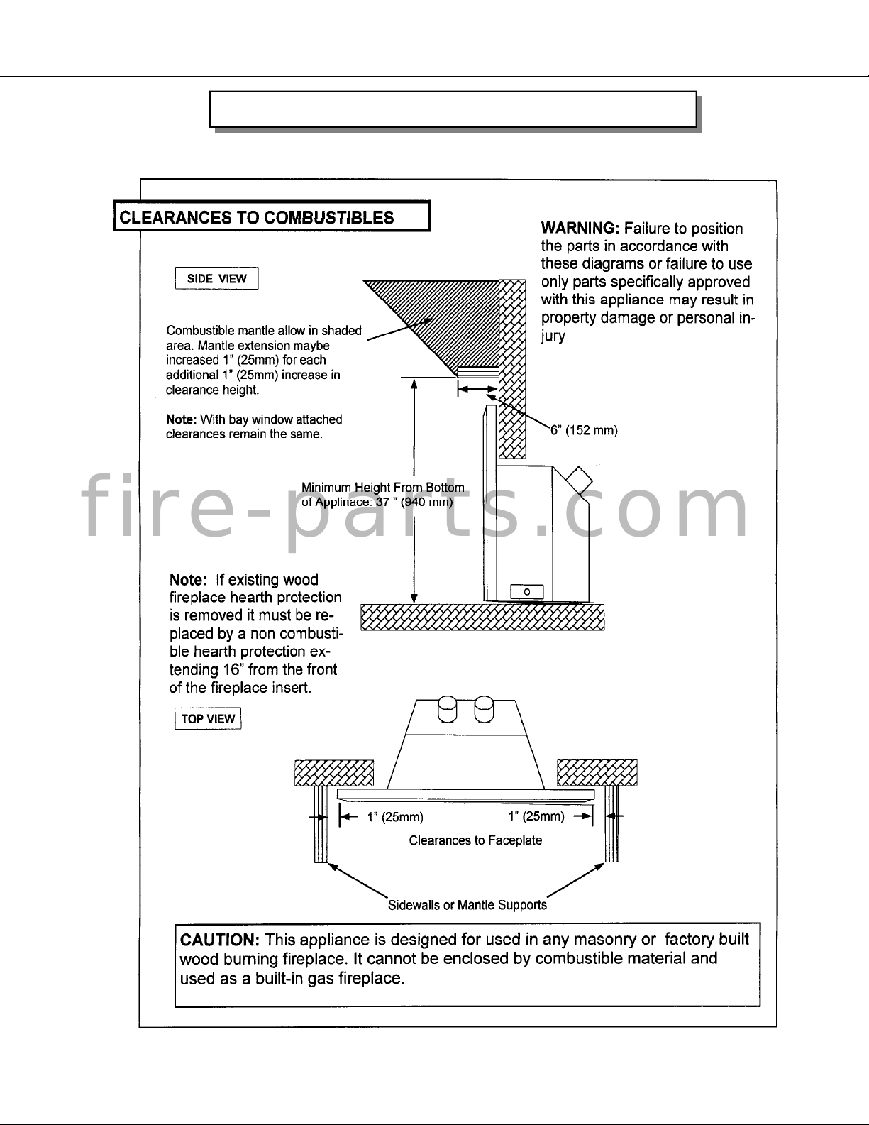
Before placing the appliance into the fireplace, check the hearth of the fireplace to see if it is
level with the front of the fireplace. If it is not, measure the depth of the hearth. Loosen the
three screws of the leveling “L” bracket at the back of the appliance. Lower it to the
measurement obtained and tighten the screws, now complete the flexible gas liners connection
to the appliance flue collars again, DO NOT MIX-UP THESE CONNECTIONS.
VENTING
INSTALLATION INSTRUCTIONS Cont...
Make sure the gas and electrical lines are properly con-
nected to the appliance. Slide the unit into the fireplace
and slide the excess flue liners material back onto the
chimney. Before the appliance is fully recessed into the
fireplace attach the faceplate onto the appliance. The re-
turn flange on the side of the face plate fits on the inside
of the mounting rails on the appliance. Attach the faceplate
to the appliance at the locations shown with the four (4)
black screws provided. Then finish with the wiring connec-
tion to the on/off switch on the side of the trim. Now fully
“seat” the unit into it’s final position
SCREW
LOCATIONS
fire-parts.com