manuals.online logo
Brands
  1. Home
  2. •
  3. Brands
  4. •
  5. Architectural Mailboxes
  6. •
  7. Outdoor Furnishing
  8. •
  9. Architectural Mailboxes 5500 Series User manual

Architectural Mailboxes 5500 Series User manual

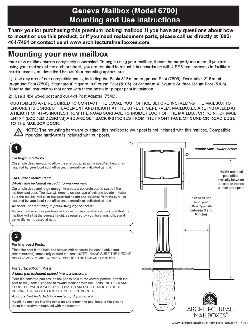
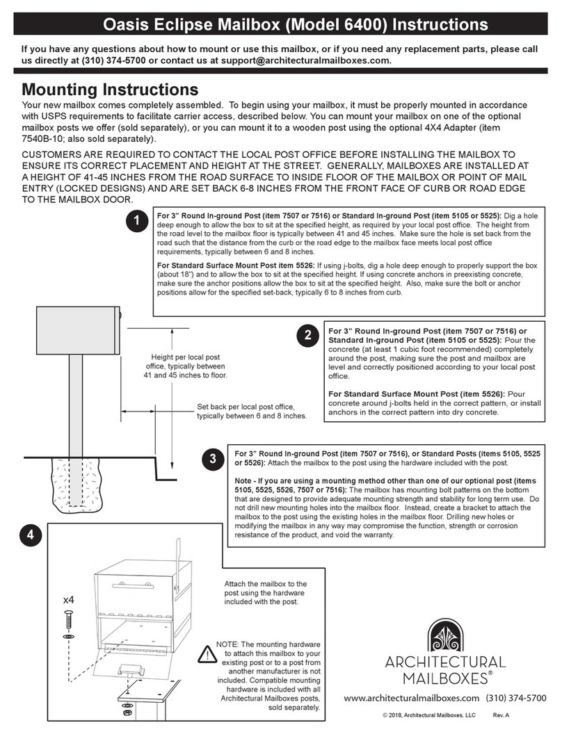
Your new mailbox comes completely assembled. To begin using your mailbox, it must be properly mounted in accordance
with USPS requirements to facilitate carrier access, described below. You can mount your mailbox on one of the optional
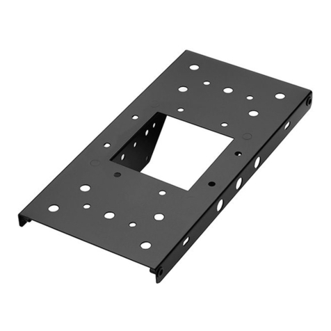
mailbox posts we offer, or you can mount it to a wooden post using the optional 4X4 Adapter (Item 7540).
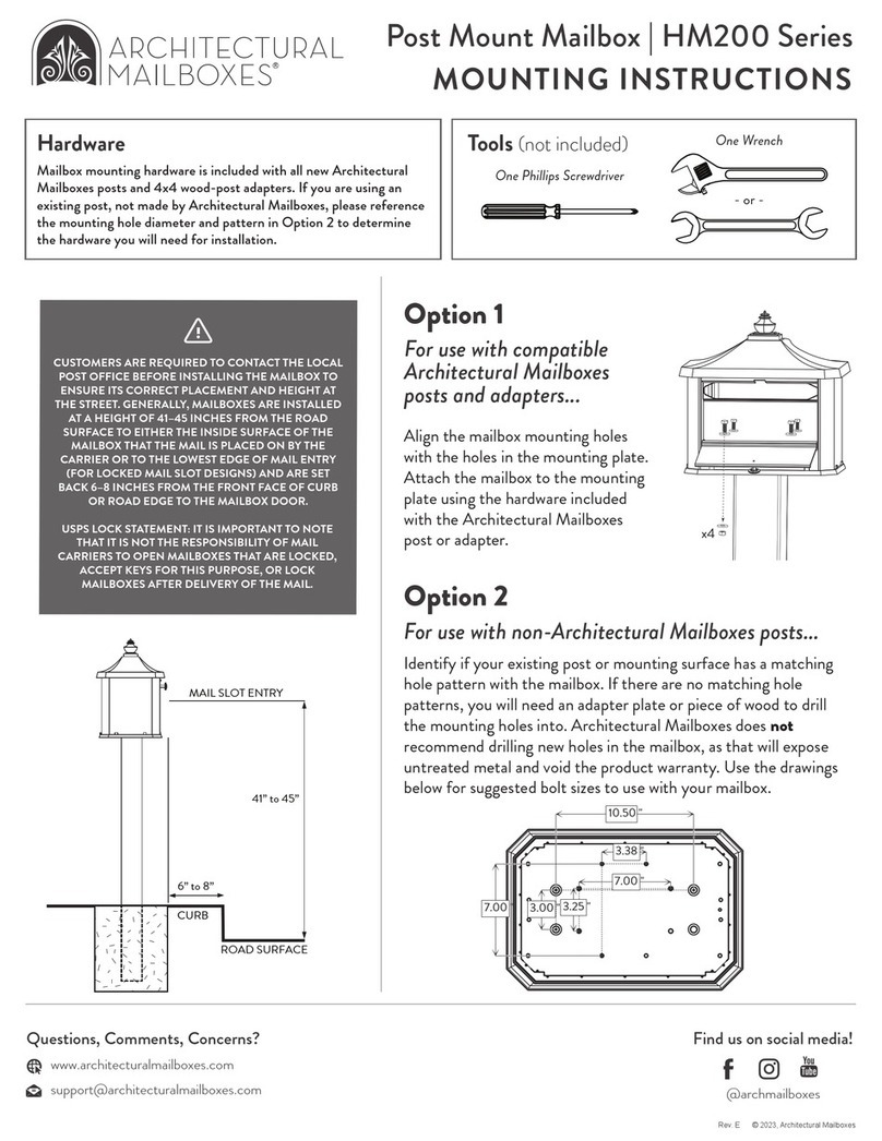
CUSTOMERS ARE REQUIRED TO CONTACT THE LOCAL POST OFFICE BEFORE INSTALLING THE MAILBOX TO
ENSURE ITS CORRECT PLACEMENT AND HEIGHT AT THE STREET. GENERALLY, MAILBOXES ARE INSTALLED AT
A HEIGHT OF 41-45 INCHES FROM THE ROAD SURFACE TO INSIDE FLOOR OF THE MAILBOX OR POINT OF MAIL
ENTRY (LOCKED DESIGNS) AND ARE SET BACK 6-8 INCHES FROM THE FRONT FACE OF CURB OR ROAD EDGE
TO THE MAILBOX DOOR.
Series 5500 Mailboxes Instructions
Mounting Instructions
Thank you for purchasing this premium mailbox. We know you'll be satisfied with the years of service it will
provide. If you have any questions about how to mount or use this mailbox, or if you need any replacement parts,
please call us directly at (310) 374-5700 or contact us at [email protected].
© 2018, Architectural Mailboxes, LLC Rev. C
Height per local post
office, typically between
41 and 45 inches to floor.
Set back per local post office,
typically between 6 and 8 inches.
For 3” Round In-ground Post (item 7507 or 7516) or Standard In-ground Post (item 5525): Dig a hole deep
enough to allow the box to sit at the specified height, as required by your local post office. The height from the
road level to the mailbox floor is typically between 41 and 45 inches. Make sure the hole is set back from the road
such that the distance from the curb or the road edge to the mailbox face meets local post office requirements,
typically between 6 and 8 inches.
For Standard Surface Mount Post (item 5526): If using j-bolts, dig a hole deep enough to properly support the
box (about 18") and to allow the box to sit at the specified height. If using concrete anchors in preexisting concrete,
make sure the anchor positions allow the box to sit at the specified height. Also, make sure the bolt or anchor
positions allow for the specified set-back, typically 6 to 8 inches from curb.
For Decorative Post (item 7510 or 7513): Refer to the instructions included with the post.
1
For 3” Round In-ground Post (item 7507 or 7516) or
Standard In-ground Post (item 5525): Pour the concrete (at
least 1 cubic foot recommended) completely around the post,
making sure the post and mailbox are level and correctly
positioned according to your local post office.
For Standard Surface Mount Post (item 5526): Pour concrete
around j-bolts held in the correct pattern, or install anchors in
the correct pattern into dry concrete.
For Decorative Post (item 7510 or 7513): Refer to the
instructions included with the post.
2
For 3” Round In-ground Post (item 7507 or 7516), or Standard Posts (items 5525 or
5526): Attach the mailbox to the post using the hardware included with the post.
For Decorative Post (item 7510 or7513): Refer to the instructions included with the post.
Note - If you are using a mounting method other than an optional post (items 5525,
5526, 7507, 7510, 7513, or 7516): The mailbox has mounting bolt patterns on the bottom
that are designed to provide adequate mounting strength and stability for long term use. Do
not drill new mounting holes into the mailbox floor. Instead, create a bracket to attach the
mailbox to the post using the existing holes in the mailbox floor. Drilling new holes or
modifying the mailbox in any way may compromise the function, strength or corrosion
resistance of the product.
3
www.architecturalmailboxes.com (310) 374-5700
R
NOTE: The mounting hardware to
attach this mailbox to your post is
not included with this mailbox.
Compatible mounting hardware is
included with our posts.
!
(310) 374-5700 www.architecturalmailboxes.com © 2018, Architectural Mailboxes 7510 Rev K
3
Attach the two halves of
the decorative post cover
to each other around the
post using the 4 tapping
screws. The cover will be
slightly loose so that it can
be raised during gardening
or lawn maintenance.
x4
Locate the correct height for the
support arm. According to USPS
requirments, the top surface of
the arm should rest from 41” to
45“ from the road surface. Refer
to the mailbox instructions for
more details.
Press the rubber pads into the
grooves of the support arm
pieces.
x6
6
Attach the finial to
the top of the post
using the 12mm
Phillips screws.
x2
Assembly Instructions
5
Attach the mailbox to the post
using the 4 large hex bolts
and 4 large washers.
Attach the mailbox to the post with 4
long Phillips screws.
If you are mounting a wider (T2 sized)
mailbox, insert a spacer in between the
mailbox and post arm at each of the
side hole locations.
Hardware (included)
Tools (not included)
Two open end wrenches Phillips head screwdriver
- or -
Thank you for purchase this premium mailbox post. We know you’ll be satisfied with the years of service it will provide. If you have any
questions about how to assemble or install this product, or if you need any replacement parts, please call us directly at (310) 374-5700 or
contact us at [email protected].
3” Round Mailbox Post with Cover and Finial (Model 7510)
Assembly Instructions
R
Then, attach the arm to the post using
the six 3/8” Phillips screws. Make sure
all screws are even and snug.
4a
4b
x 4
1a Lay post pieces on a flat surface, making sure to align
the screw holes.
2
A concrete footing is
highly recommended for
cantilever style posts.
Install the assembled post
into the ground as described
in the instructions for the
mailbox. Typical post depths
range from 12”-18” and may
vary based on your
installation application. Pay
particular attention to the
location, height, and distance
from the street.
TO INSTALL USING
TOP MOUNTING HOLES TO INSTALL USING
SIDE MOUNTING HOLES
To join the two post pieces:
x 3, large sheet metal screws
To join the two decorative covers:
x 4, tapping screws x 6, 3/8” Phillips screws
To join the two support arm
pieces:
x 4, rubber pads
To attach the finial:
x 2, 12mm Phillips screws
To attach the mailbox using
the top mounting holes:
x 4, large hex bolts
x 4x large washers
To attach the mailbox using
the side mounting holes:
x 4, long Phillips screws
x 4, nylon spacers (optional)
1
3
4 5 6
1b
x4
x4
optional
x3
!
Join the two post pieces together using the 3 sheet
metal screws.
Tighten until snug.

This manual suits for next models

1

Other Architectural Mailboxes Outdoor Furnishing manuals

Architectural Mailboxes Oasis Eclipse User manual

Architectural Mailboxes

Architectural Mailboxes Oasis Eclipse User manual

Architectural Mailboxes Geneva 6700 Guide

Architectural Mailboxes

Architectural Mailboxes Geneva 6700 Guide

Architectural Mailboxes MONTROSO MON00BPEC User manual

Architectural Mailboxes

Architectural Mailboxes MONTROSO MON00BPEC User manual

Architectural Mailboxes 7540 User manual

Architectural Mailboxes

Architectural Mailboxes 7540 User manual

Architectural Mailboxes Hamilton HM200 Series User manual

Architectural Mailboxes

Architectural Mailboxes Hamilton HM200 Series User manual

Architectural Mailboxes 2572 User manual

Architectural Mailboxes

Architectural Mailboxes 2572 User manual

Popular Outdoor Furnishing manuals by other brands

SNOWJOE Sunjoy L-GZ724PST-BPK-1 Assembly instructions

SNOWJOE

SNOWJOE Sunjoy L-GZ724PST-BPK-1 Assembly instructions

Hanover Monaco MONDN7PCSW-2-BLU manual

Hanover

Hanover Monaco MONDN7PCSW-2-BLU manual

Whittier Wood Furniture John Greenleaf Rustic Lodge 373KFDC Assembly instructions

Whittier Wood Furniture

Whittier Wood Furniture John Greenleaf Rustic Lodge 373KFDC Assembly instructions

Yardistry SENECA PRIVACY ARBOR SPA8 YM14126 installation manual

Yardistry

Yardistry SENECA PRIVACY ARBOR SPA8 YM14126 installation manual

MASTERCANOPY GHG-041 Assembly and operating instructions

MASTERCANOPY

MASTERCANOPY GHG-041 Assembly and operating instructions

PHI VILLA THD7-326-3501 Use and care guide

PHI VILLA

PHI VILLA THD7-326-3501 Use and care guide

Titan GLIDCHR Operator's manual

Titan

Titan GLIDCHR Operator's manual

Atleisure UMB-952590 Assembly & care instructions

Atleisure

Atleisure UMB-952590 Assembly & care instructions

Oxford & Garden CH60SW quick start guide

Oxford & Garden

Oxford & Garden CH60SW quick start guide

Hanover Monaco MONACO5PCSW quick start guide

Hanover

Hanover Monaco MONACO5PCSW quick start guide

Belleze 048-GM-48104 owner's manual

Belleze

Belleze 048-GM-48104 owner's manual

Safavieh PAT6745 quick start guide

Safavieh

Safavieh PAT6745 quick start guide

Hornbach 10476778 user manual

Hornbach

Hornbach 10476778 user manual

PHI VILLA 3PCS Rattan Sofa Set Assembly instructions and user's manual

PHI VILLA

PHI VILLA 3PCS Rattan Sofa Set Assembly instructions and user's manual

Forever Redwood ILLUMINATI PORCH PAVILION Assembly instructions

Forever Redwood

Forever Redwood ILLUMINATI PORCH PAVILION Assembly instructions

Sunjoy A102007903 Assembly and safety instructions

Sunjoy

Sunjoy A102007903 Assembly and safety instructions

Mosaic 155507 Assembly instructions & user manual

Mosaic

Mosaic 155507 Assembly instructions & user manual

Mercia Garden Products 0619LOG002-V4 General instructions

Mercia Garden Products

Mercia Garden Products 0619LOG002-V4 General instructions

manuals.online logo
manuals.online logoBrands
  • About & Mission
  • Contact us
  • Privacy Policy
  • Terms and Conditions

Copyright 2025 Manuals.Online. All Rights Reserved.