3
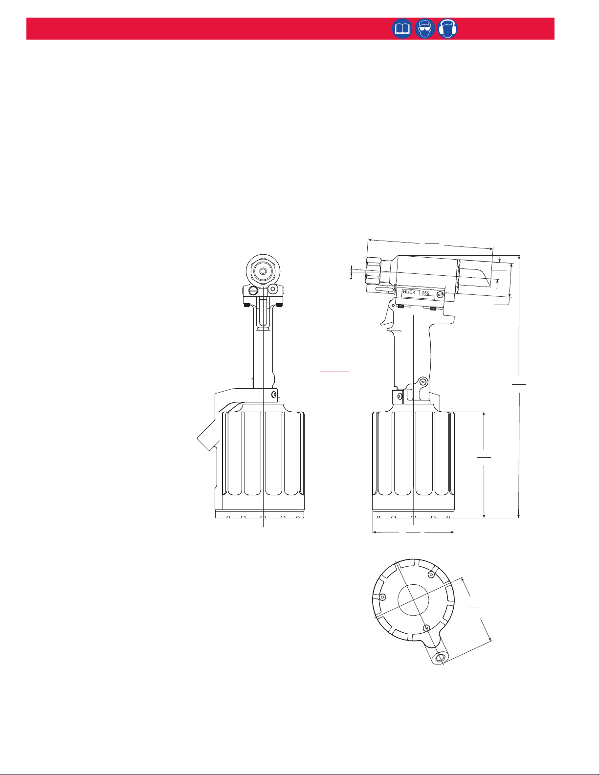
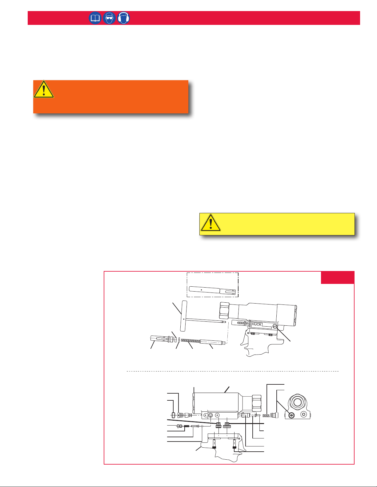
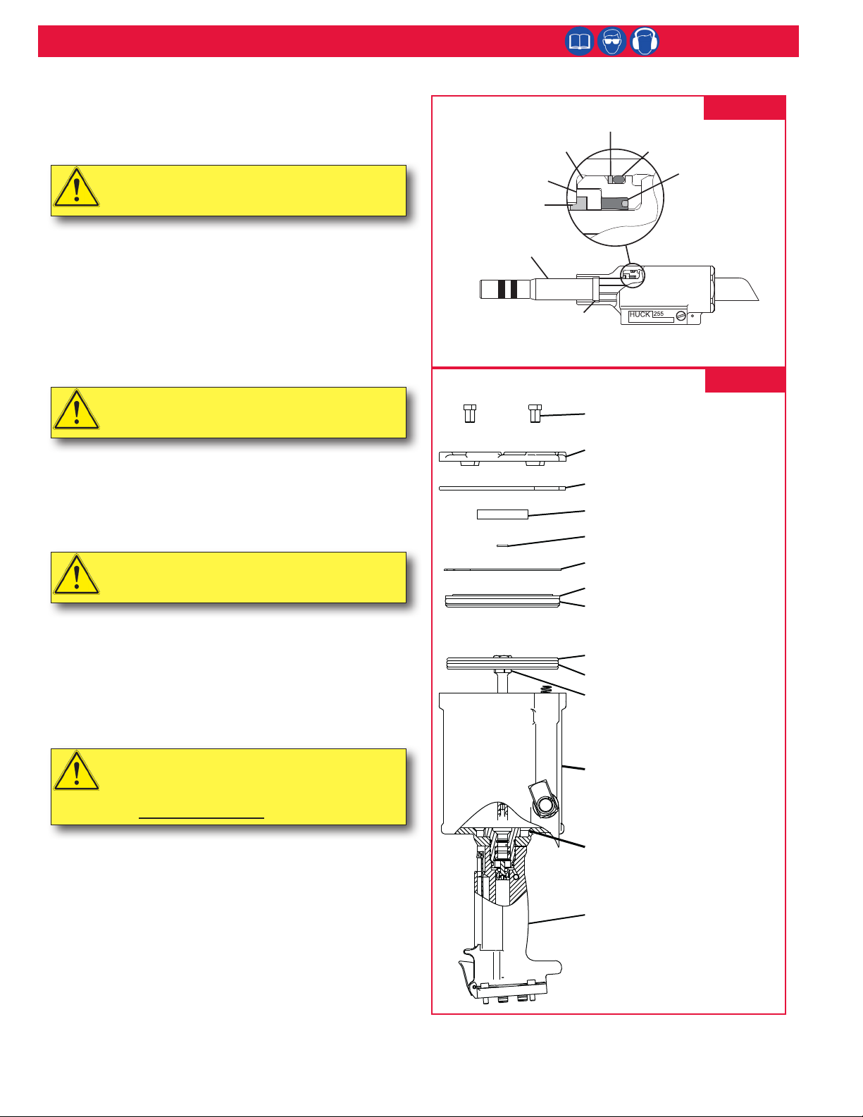
255 Blankdraulic Installation Tool (HK1014)
I. GENERAL SAFETY RULES:
1.Ahalfhourlonghands-ontrainingsessionwithqualiedpersonnelis
recommendedbeforeusingHuckequipment.
2.Huckequipmentmustbemaintainedinasafeworkingconditionatall
times.Toolsandhosesshouldbeinspectedatthebeginningofeach
shift/dayfordamageorwear.Anyrepairshouldbedonebyaqualied
repairmantrainedonHuckprocedures.
3.Formultiplehazards,readandunderstandthesafetyinstructionsbefore
installing,operating,repairing,maintaining,changingaccessorieson,
orworkingneartheassemblypowertool.Failuretodosocanresultin
serious bodily injury.
4.Onlyqualiedandtrainedoperatorsshouldinstall,adjustorusethe
assemblypowertool.
5.Donotmodifythisassemblypowertool.Thiscanreduceeectivenessof
safetymeasuresandincreaseoperatorrisk.
6.Donotdiscardsafetyinstructions;givethemtotheoperator.
7.Donotuseassemblypowertoolifithasbeendamaged.
8.Toolsshallbeinspectedperiodicallytoverifyallratingsandmarkings
required, and listed in the manual, are legibly marked on the tool. The
employer/operatorshallcontactthemanufacturertoobtainreplacement
markinglabelswhennecessary.Refertoassemblydrawingandpartslist
forreplacement.
9. Tool is only to be used as stated in this manual. Any other use is
prohibited.
10.ReadMSDSSpecicationsbeforeservicingthetool.MSDS
specicationsareavailablefromtheproductmanufactureroryourHuck
representative.
11.OnlygenuineHuckpartsshallbeusedforreplacementsorspares.Use
ofanyotherpartscanresultintoolingdamageorpersonalinjury.
12.Neverremoveanysafetyguardsorpintaildeectors.
13.Neverinstallafastenerinfreeair.Personalinjuryfromfastenerejecting
may occur.
14.Whereapplicable,alwaysclearspentpintailoutofnoseassembly
before installing the next fastener.
15.Checkclearancebetweentriggerandworkpiecetoensurethereisno
pinchpointwhentoolisactivated.Remotetriggersareavailablefor
hydraulictoolingifpinchpointisunavoidable.
16.Donotabusetoolbydroppingorusingitasahammer.Neveruse
hydraulicorairlinesasahandleortobendorprythetool.Reasonable
careofinstallationtoolsbyoperatorsisanimportantfactorin
maintainingtooleciency,eliminatingdowntime,andpreventingan
accidentwhichmaycauseseverepersonalinjury.
17.Neverplacehandsbetweennoseassemblyandworkpiece.Keephands
clear from front of tool.
18.Toolswithejectorrodsshouldneverbecycledwithoutnoseassembly
installed.
19.Whentwopiecelockboltsarebeingusedalwaysmakesurethecollar
orientationiscorrect.Seefastenerdatasheetforcorrectpositioning.
II. PROJECTILE HAZARDS:
1.Riskofwhippingcompressedairhoseiftoolispneudraulicorpneumatic.
2.Disconnecttheassemblypowertoolfromenergysourcewhenchanging
inserted tools or accessories.
3.Beawarethatfailureoftheworkpiece,accessories,ortheinsertedtool
itselfcangeneratehighvelocityprojectiles.
4.Alwayswearimpactresistanteyeprotectionduringtooloperation.The
gradeofprotectionrequiredshouldbeassessedforeachuse.
5. The risk of others should also be assessed at this time.
6.Ensurethattheworkpieceissecurelyxed.
7.Checkthatthemeansofprotectionfromejectionoffastenerorpintailis
inplaceandoperative.
8.Thereispossibilityofforcibleejectionofpintailsorspentmandrelsfrom
front of tool.
III. OPERATING HAZARDS:
1.Useoftoolcanexposetheoperator’shandstohazardsincluding:
crushing,impacts,cuts,abrasionsandheat.Wearsuitableglovesto
protecthands.
2.Operatorsandmaintenancepersonnelshallbephysicallyabletohandle
thebulk,weightandpowerofthetool.
3. Hold the tool correctly and be ready to counteract normal or sudden
movementswithbothhandsavailable.
4.Maintainabalancedbodypositionandsecurefooting.
5.Releasetriggerorstopstartdeviceincaseofinterruptionofenergy
supply.
6.Useonlyuidsandlubricantsrecommendedbythemanufacturer.
7.Avoidunsuitablepostures,asitislikelyforthesenottoallow
counteractingofnormalorunexpectedtoolmovement.
8.Iftheassemblypowertoolisxedtoasuspensiondevice,makesure
thatxationissecure.
9.Bewareoftheriskofcrushingorpinchingifnoseequipmentisnottted.
IV. REPETITIVE MOTION HAZARDS:
1.Whenusingassemblypowertool,theoperatorcanexperience
discomfortinthehands,arms,shoulders,neckorotherpartsofthe
body.
2.Whenusingtool,theoperatorshouldadoptacomfortableposture
whilemaintainingasecurefootingandavoidawkwardorobalanced
postures.
3.Theoperatorshouldchangepostureduringextendedtaskstohelpavoid
discomfort and fatigue.
4.Iftheoperatorexperiencessymptomssuchaspersistentorrecurring
discomfort,pain,throbbing,aching,tingling,numbness,burning
sensationsorstiness,thesewarningsshouldnotbeignored.The
operatorshouldtelltheemployerandconsultaqualiedhealth
professional.
V. ACCESSORIES HAZARDS:
1.Disconnecttoolfromenergysupplybeforechanginginsertedtoolor
accessory.
2.Useonlysizesandtypesofaccessoriesandconsumablesthatare
recommended.Donotuseothertypesorsizesofaccessoriesor
consumables.
VI. WORKPLACE HAZARDS:
1.Beawareofslipperysurfacescausedbyuseofthetoolandoftrip
hazardscausedbytheairlineorhydraulichose.
2. Proceed with caution while in unfamiliar surroundings; there could be
hiddenhazardssuchaselectricityorotherutilitylines.
3.Theassemblypowertoolisnotintendedforuseinpotentiallyexplosive
environments.
4.Toolisnotinsulatedagainstcontactwithelectricalpower.
5.Ensuretherearenoelectricalcables,gaspipes,etc.,whichcancausea
hazardifdamagedbyuseofthetool.
VII. NOISE HAZARDS:
1.Exposuretohighnoiselevelscancausepermanent,disablinghearing
lossandotherproblemssuchastinnitus,thereforeriskassessmentand
theimplementationofpropercontrolsisessential.
2.Appropriatecontrolstoreducetheriskmayincludeactionssuchas
dampingmaterialstopreventworkpiecefrom‘ringing’.
3.Usehearingprotectioninaccordancewithemployer’sinstructionsandas
requiredbyoccupationalhealthandsafetyregulations.
4.Operateandmaintaintoolasrecommendedintheinstructionhandbook
topreventanunnecessaryincreaseinthenoiselevel.
5.Select,maintainandreplacetheconsumable/insertedtoolas
recommendedtopreventanunnecessaryincreaseinnoise.
6.Ifthepowertoolhasasilencer,alwaysensurethatitisinplaceandin
goodworkingorderwhenthetoolisbeingoperated.
VIII. VIBRATION HAZARDS:
1.Exposuretovibrationcancausedisablingdamagetothenervesand
bloodsupplytothehandsandarms.
2.Wearwarmclothingwhenworkingincoldconditionsandkeephands
warm and dry.
3.Ifnumbness,tingling,painorwhiteningoftheskininthengersor
hands,stopusingthetool,tellyouremployerandconsultaphysician.
4.Supporttheweightofthetoolinastand,tensionerorbalancerinorder
tohavealightergriponthetool.
IX. PNEUMATIC / PNEUDRAULIC TOOL SAFETY INSTRUCTIONS:
1.Airunderpressurecancausesevereinjury.
2.Alwaysshutoairsupply,drainhoseofairpressureanddisconnecttool
fromairsupplywhennotinuse,beforechangingaccessoriesorwhen
makingrepairs.
3.Neverdirectairatyourselforanyoneelse.
4.Whippinghosescancausesevereinjury,alwayscheckfordamagedor
loosehosesandttings.
5. Cold air should be directed away from hands.
6.Wheneveruniversaltwistcouplings(clawcouplings)areused,lockpins
shallbeinstalledandwhip-checksafetycablesshallbeusedtosafeguard
againstpossiblehosetohoseorhosetotoolconnectionfailure.
7.Donotexceedmaximumairpressurestatedontool.
8.Nevercarryanairtoolbythehose.
Safety Instructions
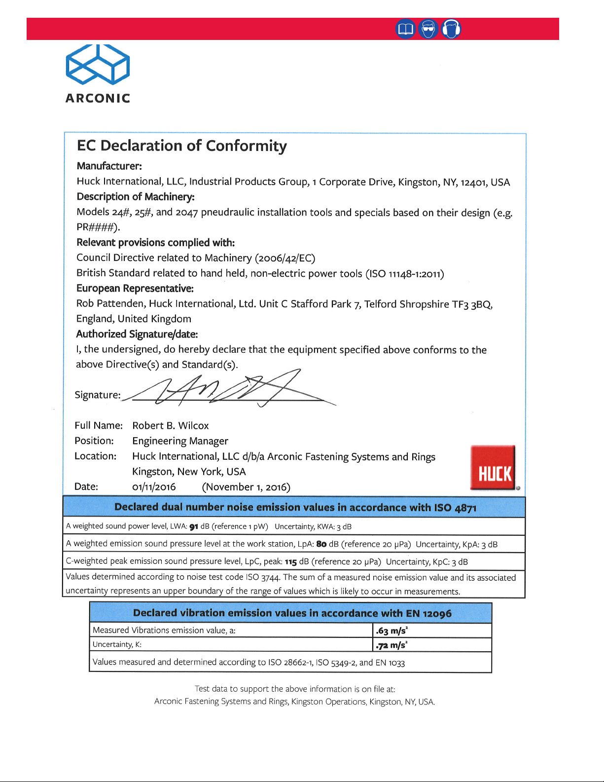
GLOSSARYOFTERMSANDSYMBOLS:
- Productcomplieswithrequirementssetforthby
therelevantEuropeandirectives.
- Readmanualpriortousingthisequipment.
- Eyeprotectionisrequiredwhileusingthis
equipment.
- Hearingprotectionisrequiredwhileusingthis
equipment.
Notes:areremindersofrequiredprocedures.
Bold, Italic type, and underline:emphasizeaspecic
instruction.
WARNINGS: Must be understood to avoid
severe personal injury.
CAUTIONS: Show conditions that will damage
equipment or structure.