Ariens 926502 - PB936 Owner's manual

Owner/Operator Manual
Models
926502 - PB936
All Seasons Power Brush
00437500 7/05
Printed in USA
ENGLIS
H
FRANÇAI
S
ESPAÑO
L
Transfer
model &
serialnumber
label from
product
registration
here.
Coller l’autocollant du
modèle et du numéro de
série dans cet encadré.
Transferir aquí la etiqueta
del modelo y número de
serie del registro del
producto.

GB - 2
Safety. . . . . . . . . . . . . . . . . . . . . . . . . . . . . . . . . . . 3
Assembly . . . . . . . . . . . . . . . . . . . . . . . . . . . . . . . . 6
Controls & Features. . . . . . . . . . . . . . . . . . . . . . . . 7
Operation. . . . . . . . . . . . . . . . . . . . . . . . . . . . . . . . 8
Storage. . . . . . . . . . . . . . . . . . . . . . . . . . . . . . . . . 11
Maintenance . . . . . . . . . . . . . . . . . . . . . . . . . . . . 12
Service & Adjustments. . . . . . . . . . . . . . . . . . . . . 14
Troubleshooting . . . . . . . . . . . . . . . . . . . . . . . . . . 17
Specifications. . . . . . . . . . . . . . . . . . . . . . . . . . . . 18
Service Parts . . . . . . . . . . . . . . . . . . . . . . . . . . . . 18
Accessories . . . . . . . . . . . . . . . . . . . . . . . . . . . . . 18
Warranty. . . . . . . . . . . . . . . . . . . . . . . . . . . . . . . . 19
THE MANUAL
Before operation of unit, carefully and completely read
your manuals. If used improperly, this unit could be
dangerous and cause personal injury or property
damage. The contents will provide you with safety
instructions for the safe use of your unit during normal
operation and maintenance.
All reference to left, right, front, or rear are given from
operator standing in operation position and facing the
direction of forward travel.
MODEL AND SERIAL NUMBERS
When ordering replacement parts or making service
inquiries, know the Model and Serial numbers of your
unit and engine.
Numbers are located on the product registration form in
the unit literature package. They are printed on a serial
number label, located on the frame of your unit.
• Record Unit Model and Serial number here.
• Record Engine Model and Serial number here.
PRODUCT REGISTRATION
The Ariens dealer must register the product at the time
of purchase. Registering the product will help the
company process warranty claims or contact you with
the latest service information. All claims meeting
requirements during the limited warranty period will be
honored, whether or not the product registration card is
returned. Keep a proof of purchase if you do not
register your unit.
Customer Note: If Dealer does not register your
product, please fill out, sign and return the product
registration card to Ariens or go to www.ariens.com.
UNAUTHORIZED REPLACEMENT PARTS
Use only Ariens replacement parts. The replacement of
any part on this unit with anything other than an Ariens
authorized replacement part may adversely affect the
performance, durability, or safety of this unit and may
void the warranty. Ariens disclaims liability for any
claims or damages, whether warranty, property
damage, personal injury or death arising out of the use
of unauthorized replacement parts.
For a brief list of replacement parts see Service Parts
in this manual. To obtain a complete parts manual, find
your model and serial number. Then go to
www.ariens.com or call 1-920-756-4664.
DISCLAIMER
Ariens reserves the right to discontinue, make changes
to, and add improvements upon its products at any
time without public notice or obligation. The
descriptions and specifications contained in this
manual were in effect at printing. Equipment described
within this manual may be optional. Some illustrations
may not be applicable to your unit.
DELIVERY
Customer Note: If you have purchased this product
without complete assembly and instruction by your
retailer, it is your responsibility to:
1. Read and understand all assembly instructions in
this manual. If you do not understand or have
difficulty following the instructions, contact your
nearest Ariens Dealer for assistance. Make sure
all assembly has been properly completed.
NOTE: To locate your nearest Ariens Dealer, call
1-920-756-4664 or go to www.ariens.com on the
internet.
TABLE OF CONTENTS
INTRODUCTION
Serial Number
Label
OS1960
Figure 1
WARNING: Improper assembly or
adjustments can cause serious injury.
© Copyright 2001, 2005 Ariens Company

GB - 3
2. Understand all Safety Precautions provided in the
manuals.
3. Review control functions and operation of the
unit. Do not operate the unit unless all controls
function as described in this manual.
4. Review recommended lubrication, maintenance
and adjustments.
5. Review Limited Warranty Policy.
6. Fill out Original Purchaser Registration Card and
return the card to Ariens Company or go to
www.ariens.com on the internet.
SAFETY ALERTS
Look for these symbols to point out
important safety precautions. They
mean:
Attention!
Personal Safety Is Involved!
Become Alert!
Obey The Message!
The safety alert symbols above and signal words below
are used on decals and in this manual. Read and
understand all safety messages.
NOTATIONS
NOTE: General reference information for proper
operation and maintenance practices.
IMPORTANT: Specific procedures or information
required to prevent damage to unit or attachment.
PRACTICES AND LAWS
Practice usual and customary safe working
precautions, for the benefit of yourself and others.
Understand and follow all safety messages. Be alert to
unsafe conditions and the possibility of minor,
moderate, or serious injury or death. Learn applicable
rules and laws in your area.
REQUIRED OPERATOR TRAINING
Original purchaser of this unit was instructed by the
seller on safe and proper operation. If unit is to be used
by someone other than original purchaser; loaned,
rented or sold, ALWAYS provide this manual and any
needed safety training before operation.
SAFETY DECALS AND LOCATIONS
ALWAYS replace missing or damaged Safety Decals.
Refer to figure below for Safety Decal locations.
1. WARNING!
SAFETY
WARNING: To avoid injury to hands and
feet, always disengage clutches, shut off
engine, and wait for all movement to stop
before unclogging or working on snow
brush.
Keep hands and feet away from brush.
DANGER: IMMINENTLY HAZARDOUS
SITUATION! If not avoided, WILL RESULT
in death or serious injury.
WARNING: POTENTIALLY HAZARDOUS
SITUATION! If not avoided, COULD
RESULT in death or serious injury.
CAUTION: POTENTIALLY HAZARDOUS
SITUATION! If not avoided, MAY RESULT
in minor or moderate injury. It may also be
used to alert against unsafe practices.
Read Owner/Operator Manual.
• Allow operation only by properly
trained adult, never children.
08000018
1
Figure 2 OS3010
2
3

GB - 4
2. DANGER!
• Read the Owner’s Manual.
• Adjust brush height before operating.
• Engage traction drive clutch before attachment
clutch.
• Operating on irregular terrain could cause the
brush to dig in and drive the machine rearward.
3. CAUTION!
Engage traction drive clutch before attachment clutch.
SAFETY RULES
Read, understand, and follow all safety practices in
Owner/Operator Manual before beginning assembly or
operating. Failure to follow instructions could result in
personal injury and/or damage to unit.
ALWAYS remove key and/or wire from spark plug
before assembly, maintenance or service.
Unintentional engine start up can cause death or
serious injury.
Complete a walk around inspection of unit and work
area to understand:
• Work area • Your unit • All safety decals
ALWAYS check overhead and side clearances
carefully before operation. ALWAYS be aware of traffic
when operating along streets or curbs.
Keep children and people away. Keep children out of
work area and under watchful care of a responsible
adult.
NEVER allow children to operate or play on or near
unit. Be alert and shut off unit if children enter area.
DO NOT allow adults to operate unit without proper
training.
Keep area of operation clear of all toys, pets, and
debris. Thrown objects can cause injury.
Check for weak spots on docks, ramps or floors. Avoid
uneven work areas and rough terrain. Stay alert for
hidden hazards.
Avoid uneven and rough terrain. DO NOT operate near
drop-offs, ditches, or embankments. Unit can suddenly
turn over if a wheel is over the edge of a cliff or ditch, or
if an edge caves in.
Falling snow, fog, etc. can reduce vision and cause an
accident. Operate unit only when there is good visibility
and light.
Only trained adults may operate unit.
Training includes actual operation.
NEVER operate unit after or during the use of
medication, drugs or alcohol. Safe operation requires
your complete and unimpaired attention at all times.
NEVER allow anyone to operate this unit when their
alertness or coordination is impaired.
DO NOT operate unit without wearing adequate outer
garments. Wear adequate safety gear, including safety
glasses with side shields, and protective gloves. Wear
proper footwear to improve footing on slippery
surfaces.
DO NOT wear loose clothing or jewelry and tie back
hair that may get caught in rotating parts.
Protect eyes, face and head from objects that may be
thrown from unit. Wear appropriate hearing protection.
Avoid sharp edges. Sharp edges can cut. Moving parts
can cut off fingers or a hand.
ALWAYS keep hands and feet away from all rotating
parts during operation. Rotating parts can cut off body
parts.
NEVER place your hands or any part of your body or
clothing inside or near any moving part while unit is
running.
ALWAYS keep hands away from all pinch points.
DO NOT touch unit parts which might be hot from
operation. Allow parts to cool before attempting to
maintain, adjust or service.
Never direct discharge towards persons or property
that may be injured or damaged by thrown objects. Use
extreme caution on gravel surfaces. Stay alert for
hidden hazards or traffic.
Deflected materials can cause injury and property
damage.
Always stand clear of the discharge area when
operating this unit.
Keep people away from unit while
operating.
Never direct discharge towards
persons or property that may be
injured or damaged by thrown objects.
Stop engine, remove key, read
manual before making any repairs,
adjustments.
ONLY use clean-out tool to clear
blockages. NEVER use your hands.
Wear appropriate hearing protection.
OL437
0
OL091
0
OL4010
OL4690

GB - 5
Fumes from engine exhaust can cause injury or death.
DO NOT run engine in an enclosed area. Always
provide good ventilation.
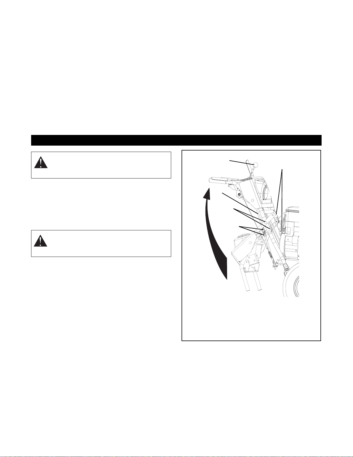
ALWAYS disengage attachment, stop unit and engine,
remove key and allow moving parts to stop before
leaving operator’s position.
Read, understand, and follow all instructions in the
manual and on the machine before starting.
Understand:
• How to operate all controls.
• The functions of all controls.
• How to STOP in an emergency.
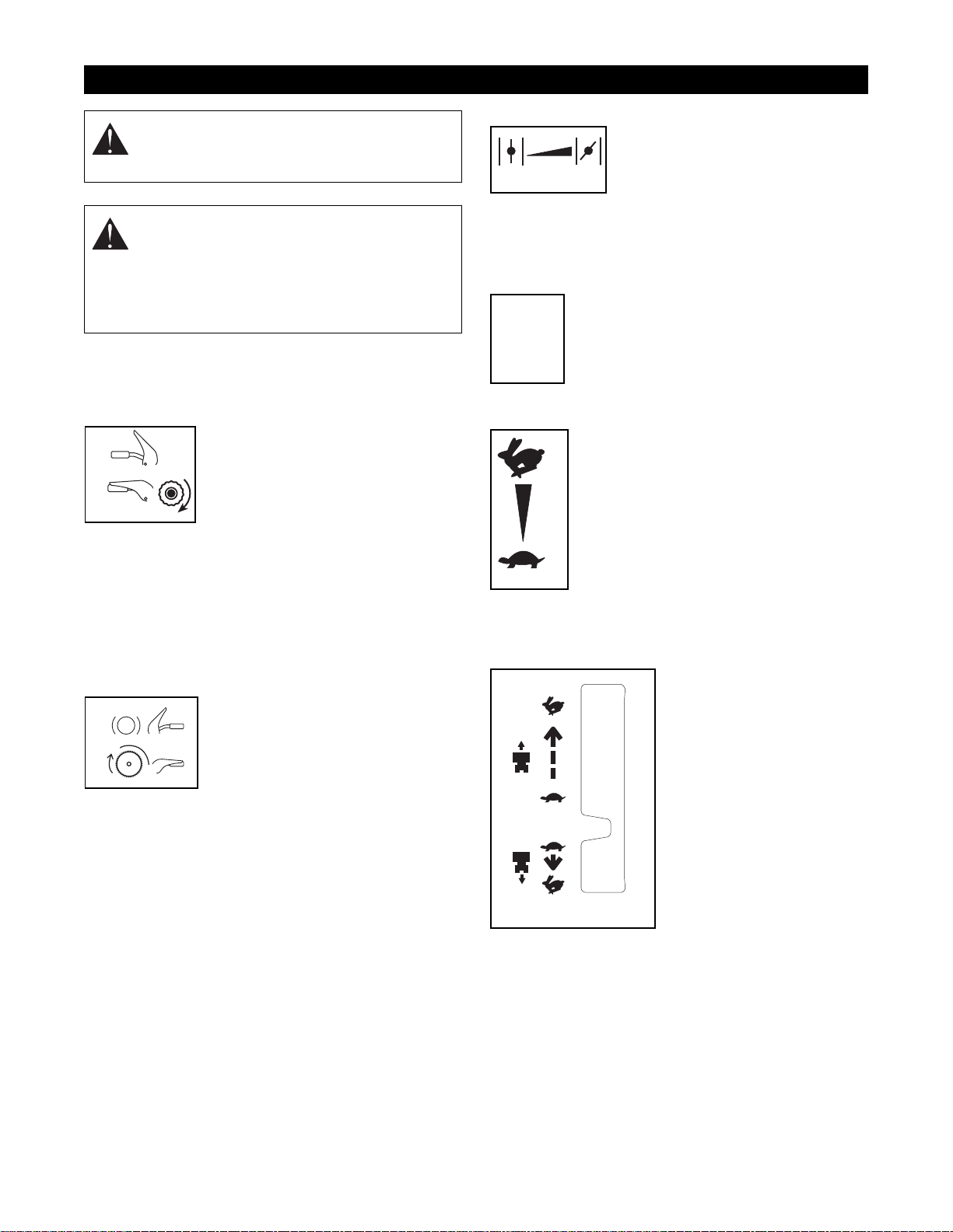
Before starting engine, disengage control(s).
Use only approved extension cords and receptacles
when starting units equipped with electric starter. DO
NOT connect electric starter cord to any wiring system
that is not a three-wire grounded system.
ALWAYS allow unit and engine to adjust to outdoor
temperatures before clearing snow.
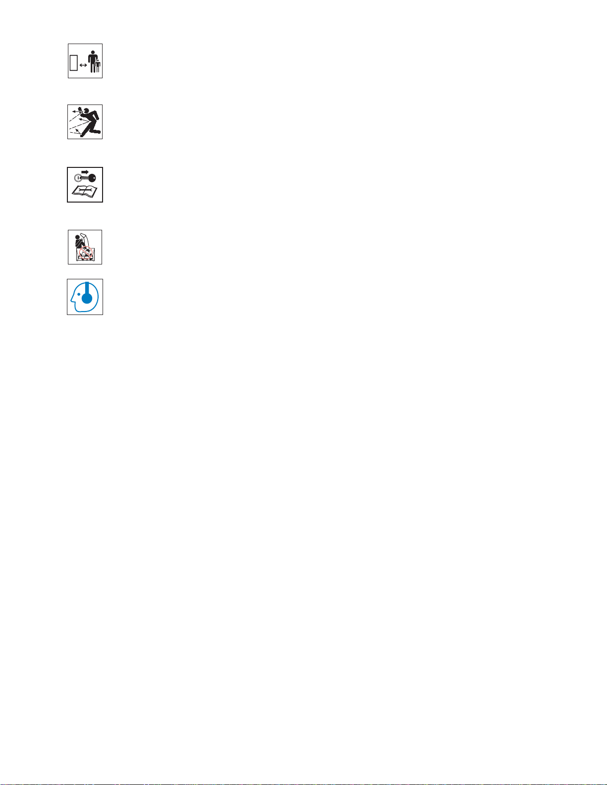
Always be sure of your footing, especially when
operating in reverse or leaving the operator’s position.
Walk, never run during operation.
DO NOT operate at too fast a rate.
Slow down and turn corners slowly.
Do not operate in reverse unless absolutely necessary.
ALWAYS back up slowly. Always look down and behind
before and while backing.
Disengage attachment drive when traveling from one
work area to another.
Abnormal Vibrations are a warning of trouble. Striking a
foreign object can damage unit. Immediately stop unit
and engine. Remove key and wait for all moving parts
to stop. Remove wire from spark plug. Inspect unit and
make any necessary repairs before restart.
Before cleaning, removing clogs or making any
inspections, repairs, etc.: disengage clutch(es),
stop unit and engine, remove key, allow moving
parts to stop. Allow hot parts to cool.
Run unit a few minutes after clearing snow to prevent
freeze-up of attachment.
Disengage attachment when not in use. Never leave a
running unit unattended. ALWAYS shut off engine
before leaving unit. ALWAYS remove key to prevent
unauthorized use.
Never carry passengers.
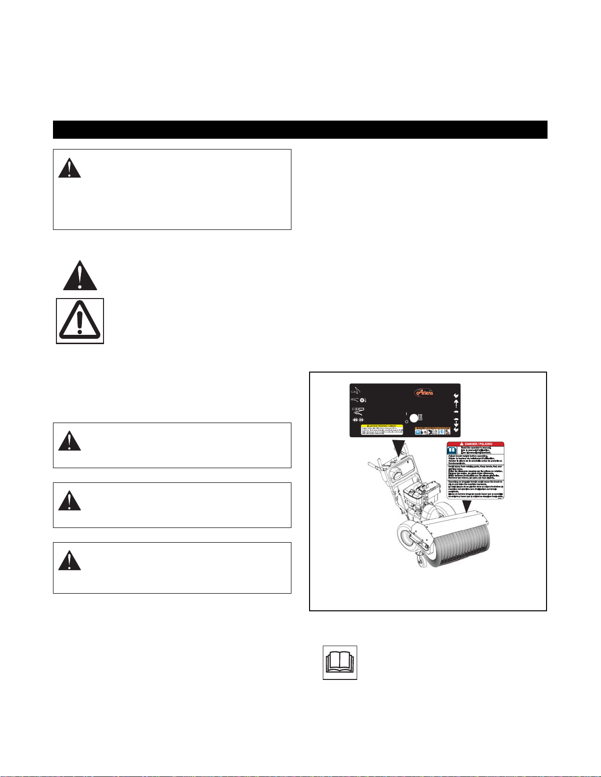
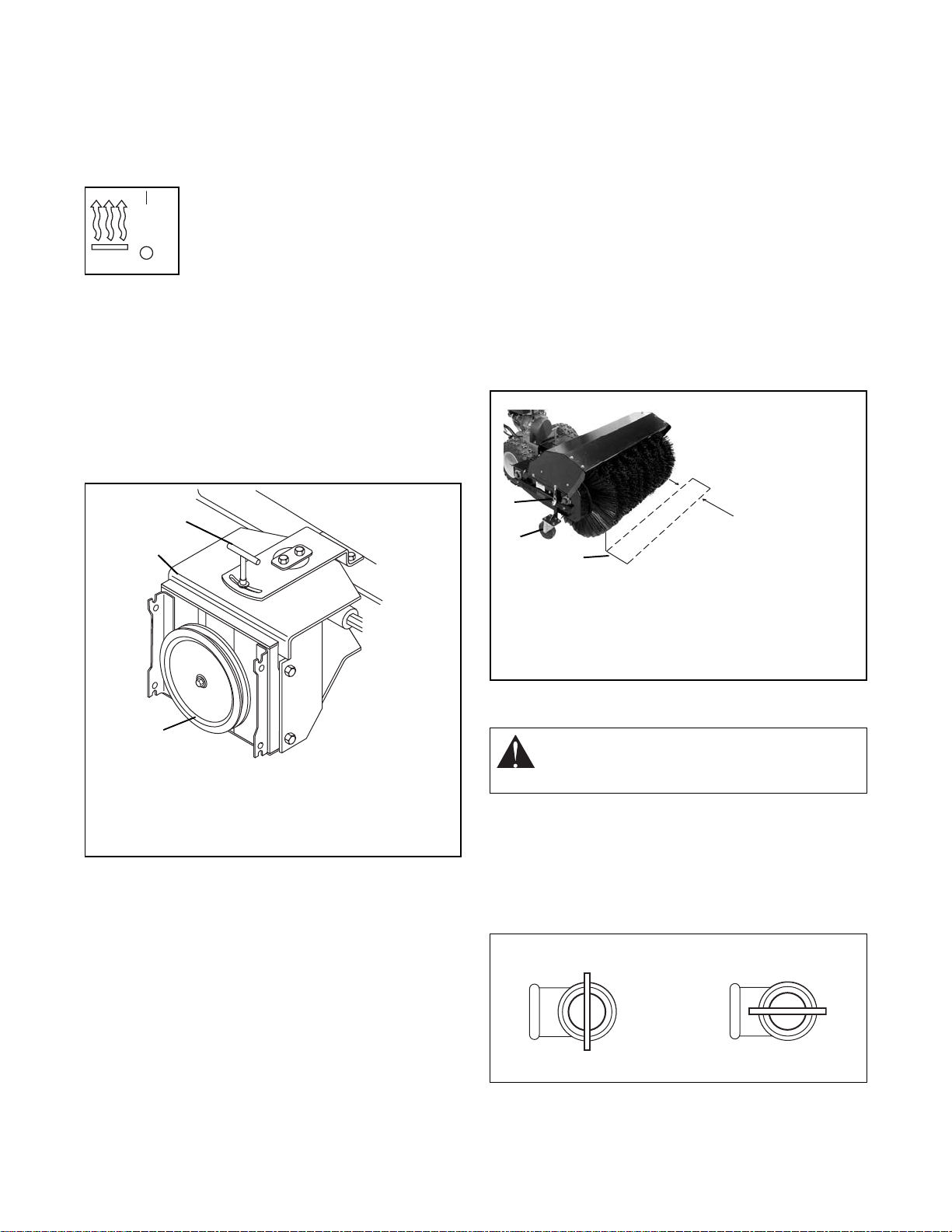
Adjust brush height before operating. Engage traction
drive clutch before attachment clutch. If brush is set too
low or if terrain is irregular brush can drive machine
rearward.
DO NOT operate on steep slopes. DO NOT clear snow
across the face of slopes. Keep all movement on
slopes slow and gradual. DO NOT make sudden
changes in speed or direction. Use a slow speed to
avoid stops or shifts on slopes. Avoid starting or
stopping on a slope.
DO NOT park unit on a slope unless absolutely
necessary. When parking on a slope always block the
wheels.
ALWAYS shut off engine, remove key, and close fuel
shut-off valve or drain fuel when transporting unit on a
truck or trailer.
Use extra care when loading or unloading unit onto
trailer or truck.
Secure unit chassis to transport vehicle. NEVER
secure from rods or linkages that could be damaged.
DO NOT transport machine while engine is running.
Keep unit free of ice or other debris. Clean up oil or fuel
spills.
This product is equipped with an internal combustion
type engine. DO NOT use unit on or near any
unimproved, forest-covered or brush covered land
unless exhaust system is equipped with a spark
arrester meeting applicable local, state or federal laws.
A spark arrester, if it is used, must be maintained in
effective working order by operator.
Fuel is highly flammable and its vapors are explosive.
Handle with care. Use an approved fuel container.
NO smoking, NO sparks, NO flames. ALWAYS allow
engine to cool before servicing.
NEVER fill fuel tank when engine is running or hot from
operation.
NEVER fill or drain fuel tank indoors.
Replace fuel cap securely and clean up spilled fuel.
Never fill containers inside a vehicle or on a truck or
trailer bed with a plastic liner. Always place containers
on the ground away from your vehicle before filling.
When practical, remove gas-powered equipment from
the truck or trailer and refuel it on the ground. If this is
not possible, then refuel such equipment on a trailer
with a portable container, rather than from a gasoline
dispenser nozzle.
Keep the nozzle in contact with the rim of the fuel tank
or container opening at all times until fueling is
complete. Do not use a nozzle lock-open device.
If fuel is spilled on clothing, change clothing
immediately.
Before tipping unit up onto housing, remove fuel so no
spills will occur. Ensure unit is secure and will not tip
over during maintenance.
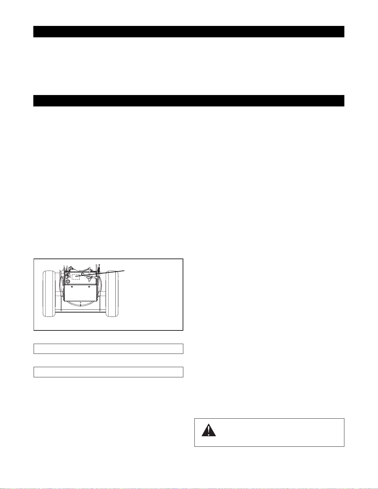
Adjust brush height before operating. Refer to
Operation.

GB - 6
Before separating brush attachment from unit frame,
remove fuel so no spills will occur. Ensure unit is
secure and will not tip over during maintenance.
ALWAYS keep protective structures, guards, and
panels in good repair, in place and securely fastened.
NEVER modify or remove safety devices.
DO NOT change engine governor settings or
over-speed engine.
Fumes from engine exhaust can cause injury or death.
DO NOT run engine in an enclosed area. Always
provide good ventilation.
ALWAYS maintain unit in safe operating condition.
Damaged or worn out muffler can cause fire or
explosion.
Keep all hardware properly tightened.
Maintain or replace safety and instruction labels, as
necessary.
NEVER store unit with fuel in fuel tank, inside a
building where any ignition sources are present such
as hot water heaters, space heaters, or clothes dryers.
Allow the engine to cool before storing in any
enclosure.
Shut off fuel and allow engine to cool completely before
storing in closed area or covering unit.
For extended storage, clean unit thoroughly. See
Engine Manual for proper storage.
Use only attachments or accessories designed for your
unit.
Check components frequently. If worn or damaged,
replace with manufacturer’s recommended parts.
Tools Required:
• Open-End Wrenches: 3/8, 7/16, 1/2, 9/16" and/or
Adjustable Wrench
• Tire Gauge
Unpacking Unit
Unfold Handlebar (Figure 3)
1. Remove the lower and loosen the upper wing
knobs on the handlebar assembly.
2. Loosen the wing nuts on the shift rod.
3. Put the speed selector lever in the first forward
position.
4. Rotate the handlebars into operating position.
5. Install and tighten all wing knobs and wing nuts
on the handlebar assembly and shift rod.
Check Function of Dual Handle Interlock
Without the engine running, press down (engage) both
clutch levers. Release attachment clutch lever.
Attachment clutch should remain engaged until traction
clutch lever is released, then both clutches must
disengage. If they do not, contact your dealer for
repairs.
Check Tire Pressure
Check tire pressure and adjust to the pressure listed on
tire sidewall.
ASSEMBLY
WARNING: AVOID INJURY. Read and
understand the entire Safety section
before proceeding.
WARNING: Dropping or tipping over
boxed unit could result in personal injury or
damage to unit.
1.Wing Knobs
2.Wing Nut
3.Bolt
4.Shift Rod
5.SpeedSelector
Lever
Figure 3 OS3020
1
1
4
2, 3
5

GB - 7
Check Engine Crankcase Oil
IMPORTANT: Engine is shipped with 5W-30 oil in
crankcase. Refer to Engine Manual for detailed
instructions.
Fill Engine Fuel Tank
Refer to Engine Manual for proper type and capacity.
Check Function of all Controls
Ensure unit runs and performs properly. Refer to
Operation.
Run-in Attachment Belt
1. Start unit in a well-ventilated area according to
Starting and Shut Off on page 10.
2. Engage attachment clutch lever and run
attachment for about 15 minutes.
3. Stop unit, wait for all moving parts to stop, and
remove spark plug wire.
4. Adjust belt finger, if necessary. See Attachment
Drive Belt Replacement on page 16.
5. Adjust clutch idler according to Attachment
Clutch/Brake Adjustment on page 14.
1. Traction Drive Clutch Lever
2. Heated Handles Switch
3. Speed Selector Lever
4. Attachment Clutch Lever
5. Recoil Starter Handle
6. Engine Shut Off Switch
7. Throttle
8. Oil Fill/Dipstick
9. Brush Guard
10. Brush
11. Height Adjustment Wheels
12. Fuel Shut Off Valve
13. Fuel Fill Cap
14. Remote Differential Lock
15. Choke
16. Engine Air Cleaner (Climate Guard)
17. Oil Drain Plug
18. Heated Handles
CONTROLS AND FEATURES
Figure 4
8
913
5
4
3
1
10
11
18
2
15
7
16
14 6
12
17 OS3025
OS3030
OS3035

GB - 8
STANDARD CONTROLS
See 4 for all Controls and Features locations.
Traction Drive Clutch - Left Hand Lever
Squeeze the Traction Drive Clutch
Lever against the Handlebar (1) to
engage wheel drive for propelling
unit.
Release lever (2) to stop movement.
NOTE: When traveling to or from the
area to be cleared, press down on the handlebars
enough to raise the front of the unit slightly off the
surface. Engage the traction drive clutch without
engaging the attachment drive clutch.
NOTE: Traction drive clutch should be engaged before
the attachment clutch when brushing.
Attachment Drive Clutch - Right Hand Lever
Squeeze Attachment Clutch Lever
against Handlebar (1) to engage
brush. Release clutch lever (2) to
disengage power and apply brake to
brush.
IMPORTANT: If the belt squeals
when the attachment clutch lever is engaged, the
attachment drive may be frozen. Immediately release
the attachment clutch lever and move the unit into a
heated area to thaw.
Dual Handle Interlock
When Attachment Clutch and then Traction Drive
Clutch are engaged, the Attachment Clutch will remain
engaged (lever down) if released. To stop brush,
release Traction Drive Clutch and both clutches will
disengage.
Choke Control Move choke control right to close
choke (2). A closed choke reduces
air to engine for easier start. Move
choke control to the left to open
choke for normal operation (1).
IMPORTANT: Gradually open choke after engine
starts.
Engine Shut Off Switch
Press the switch to "O" (off) to stop the
engine. The switch must be pressed to "I"
(on) to start the engine.
1. On
2. Off
Throttle The Throttle controls the engine speed. To
increase or decrease the engine speed,
adjust to:
1. Fast (normal or warm starts)
2. Part-Throttle
3. Slow (cold weather starts)
Speed Selector
Position the Speed Selector in the appropriate speed
notch to control forward and reverse travel.
Forward:
(6) Fastest
(1) Slowest
Reverse:
(1) Slow
(2) Fast
IMPORTANT: DO NOT
change motion from forward
to reverse with clutch
engaged. Forward speed can
be changed without
declutching.
Recoil Starter Handle
When pulled, handle will turn engine over.
Headlight
The headlight operates only when the engine is
running.
OPERATION
WARNING: AVOID INJURY. Read and
understand the entire Safety section
before proceeding.
WARNING: To avoid injury to hands and
feet, always disengage clutches, shut off
engine, and wait for all movement to stop
before unclogging or working on snow
brush.
Keep hands and feet away from brush.
2
1
OL270
1
2
1OL269
1
21 OS202
0
OM100
1
I
O
ON
OFF
1
2
3
OL2073
OS1192
6
1
1
2

GB - 9
Remote Differential
Squeeze and hold the remote differential lever to lock
differential so both wheels drive and provide better
traction. Release the remote differential lever to allow
easier steering.
Heated Handles
Turn the heated handles switch to the
ON (1) position to activate. Turn the
switch to the OFF (2) position to
deactivate.
IMPORTANT: Do not activate heated
handles when using brush in warm weather.
BRUSH ANGLE ADJUSTMENT
To change the angle of the brush:
1. Release the attachment clutch and then the
traction clutch.
2. Loosen the T-nut on top of the adapter frame and
turn the brush as needed. See Figure 5.
3. Retighten the T-nut.
BRUSH HEIGHT ADJUSTMENT
IMPORTANT: If brush height is set too low, brush can
drive machine rearward when attachment clutch is
engaged. Engage brush slowly with brush set at proper
height.
Adjust caster wheels to the hole nearest 1/8-1/4 inch
(3-6 mm) above surface. For hard surfaces, adjust the
caster wheels so that brush just touches surface. The
brush works best with the brush properly leveled. To
adjust the brush height:
1. Move the brush to a dusty, flat surface. Leave the
engine running.
2. Start the brush at a slow speed. Run the brush in
a stationary position for 30 seconds.
3. Lift the brush head assembly off the ground and
reverse the unit to move it away from the swept
area.
4. Stop engine and allow all moving parts to stop.
5. Check the width of the swept area. The brush
pattern should be 2-3 inches (5.08-7.6 cm) wide,
running the length of the brush. (See Figure 6).
6. To adjust, remove the caster wheel support pins
(one each side). Slide caster wheel supports up
or down as required. Align the holes in the outer
sleeve with the holes in the wheel supports.
7. Reinstall the adjustment pins at the new position.
8. Repeat steps 1- 7 until proper adjustment is
attained.
FUEL SHUT-OFF VALVE
IMPORTANT: The fuel shut-off valve MUST be in the
closed position prior to transporting the unit.
The fuel shut-off valve has two positions:
• Closed Position: Use this position to service,
transport, or store the unit.
• Open Position: Use this position to run the unit.
OS1950
1
2
Figure 5
1.T-Nut
2.Brush Adapter Housing
3.Attachment Drive Pulley
1
2
3
OSs0083
WARNING: AVOID INJURY. Read and
understand the entire Safety section before
proceeding.
Figure 6
1.Swept Area
2.Caster Wheel 3.Height
Adjusting Pin
1
2
3
2-3 in
(5.08-7.6 cm)
OS0061
Figure 7
OPENCLOSED

GB - 10
FILLING FUEL TANK
To add fuel to the tank:
1. ALWAYS place unit in an open, well- ventilated
area.
2. Stop engine and allow to cool.
3. Clean fuel cap and surrounding area to prevent
dirt from entering the fuel tank.
4. Remove cap.
IMPORTANT: See engine manual for correct type and
grade of fuel to use.
5. Fill fuel tank to within 1/2 inch (1.27 cm) below
bottom of filler neck. Tank capacity is 4.0 qts
(3.8 liters).
6. Replace fuel cap and tighten.
7. ALWAYS clean up any spilled fuel.
PRE-START
1. Check Engine Air Cleaner Position (Climate
Guard)
IMPORTANT: See Engine Manual for correct
orientation of air cleaner cover prior to starting engine.
2. Check Function of Clutches
Brush must stop quickly when attachment clutch lever
is released.
Wheels must stop quickly when traction drive clutch
lever is released.
If clutches do not engage or disengage properly, adjust
or repair before operation (see Service and
Adjustments).
3. Check Dual Handle Interlock
Without the engine running, press down (engage) both
clutch levers. Release attachment clutch lever.
Attachment clutch should remain engaged until traction
clutch lever is released, then both clutches must
disengage.
If clutches do not engage or disengage properly, adjust
or repair before operation (see Service and
Adjustments).
4. Check Remote Differential
Test the remote differential lock before starting.
Squeeze and hold the remote differential lever to lock
differential so both wheels drive and provide better
traction. Release the remote differential lever to allow
easier steering.
5. Adjust Brush
Adjust brush height and angle before operation. See
Brush Adjustments.
6. Check Engine Fuel and Crankcase Oil
Check and add fuel if required. Check that the engine
crankcase oil is full using dipstick. Refer to Engine
Manual for detailed instructions.
TO STOP IN AN EMERGENCY
Immediately release both control levers to stop unit in
an emergency. Stop engine and wait for all rotating
parts to stop before leaving operator’s position.
STARTING AND SHUT OFF
IMPORTANT: At start-up, allow unit and engine to
adjust to the outside temperature before operating.
Before shut-off, run unit a few minutes to prevent
freeze-up.
NOTE: Try out each control without the engine running
to see how they work and what they do.
Manual Start
1. Make sure that the traction clutch and attachment
clutch levers are fully disengaged.
2. Turn on engine shut-off switch ("I").
3. If engine is cold, apply choke. A warm engine
requires less choking than a cold engine. See
Engine Manual for detailed instructions.
4. Set throttle to proper starting position.
5. Pull rope with a rapid continuous full arm stroke.
Let rope rewind slowly.
IMPORTANT: DO NOT let Starter Handle snap against
Starter.
WARNING: FLAMMABLE FUEL and its
EXPLOSIVE VAPORS can result in death
or serious injury. Handle fuel with extreme
care. ALWAYS use an approved fuel
container. NO Smoking! NO Lighted
Materials! No Open Flames! Allow engine
to cool before any service.
This side out for use ABOVE 32°F
(0°C).
This side out for use BELOW 32°F
(0°C).
WARNING: AVOID INJURY. Read and
understand the entire Safety section
before proceeding.

GB - 11
6. Repeat until engine starts. (If engine does not
start, refer to Troubleshooting.)
7. Adjust choke as needed.
8. Set throttle to Part Throttle or Slow position for
adaptation to outside temperature or travel. Set
throttle to Fast position for normal operation.
Shut Off
1. Release attachment clutch lever and wait for all
moving parts to come to a complete stop.
2. Release traction drive clutch lever and allow unit
to come to a complete stop.
3. Run unit a few minutes after use to prevent
freeze-up.
4. Move throttle to Part Throttle or Slow position.
5. Turn off engine shut-off switch ("O").
USING THE BRUSH
After proper Pre-Start and Starting:
1. Select speed control position and direction.
IMPORTANT: DO NOT overload unit capacity by
sweeping at too fast a rate.
2. Engage the traction drive clutch first.
3. Engage the attachment clutch next.
Tips for Sweeping
To clear an area, run unit in an overlapping series of
paths. For large areas, start in the middle and sweep
debris to each side, so it is not cleared more than once.
ALWAYS direct discharge away from area to be
cleared and with direction of the wind.
Snow is best removed as soon as possible after snow
fall.
Tips for Dethatching
Dethatch in the spring to clear winter undergrowth.
Adjust brush height so it just touches the grass.
Set the brush angle full left or full right so thatch gets
cleared only once.
Dethatch dry grass.
Use a slow speed to clear thatch without damaging the
lawn.
TRAVELING
To travel from one work area to another:
1. Set throttle to SLOW position or slightly higher.
2. Press down the handlebars enough to raise the
front of the unit slightly off the surface.
3. Engage traction clutch without engaging the
attachment drive clutch.
TRANSPORT
ALWAYS shut off engine and close fuel shut-off when
transporting unit on a truck or trailer.
Use extra care when loading or unloading unit onto
trailer or truck.
Secure unit chassis to transport vehicle. NEVER
secure from rods or linkages that could be damaged.
DO NOT transport machine while engine is running.
SHORT TERM
IMPORTANT: NEVER spray unit with high-pressure
water or store unit outdoors.
Run unit a few minutes after each use to free unit of
any debris.
Inspect unit for visible signs of wear, breakage or
damage.
Keep all nuts, bolts and screws properly tightened and
know unit is in safe working condition.
Close fuel shut-off valve.
Store unit in a cool, dry protected area.
LONG TERM
Clean unit thoroughly with mild soap and low pressure
water and lubricate (see Maintenance). Touch up all
scratched painted surfaces.
Remove weight from wheels by putting blocks under
frame or axle.
When storing unit for extended periods of time, remove
all fuel from tank and carburetor (run dry). Refer to
Engine Manual.
STORAGE
WARNING: AVOID INJURY. Read and
understand the entire Safety section
before proceeding.

GB - 12
Ariens Dealers will provide any service or adjustments
which may be required to keep your unit operating at
peak efficiency. Should engine service be required,
contact an Ariens dealer or an authorized engine
manufacturer's service center.
SERVICE POSITION
IMPORTANT: DO NOT tip unit up onto brush. Remove
the brush if maintenance requires tipping the unit
forward. Ensure unit is secure and will not tip over.
Strap or clamp unit onto bench if required.
To access components in the unit frame:
1. Shut off engine and allow unit to cool completely.
Place unit on a flat level surface.
2. Remove belt cover (Figure 8).
3. Remove the rear cap screws from the bottom
cover. Loosen the side cap screws and remove
the bottom cover before separating unit.
4. Loosen cap screws and carefully rotate belt
fingers away from belt and sheave (Figure 8).
IMPORTANT: Use care when rotating the belt fingers.
DO NOT bend belt fingers out of shape.
5. Remove attachment drive belt from engine
sheave (it may be necessary to turn engine
sheave using recoil starter handle).
6. Support unit frame and brush attachment.
7. Remove cap screws securing attachment to unit
frame (one on each side). Tip attachment and
frame apart on pivot rod.
8. Remove attachment belt from attachment pulley.
9. Separate frame from brush.
MAINTENANCE SCHEDULE
The chart below shows the recommended
maintenance schedule that should be performed on a
regular basis. More frequent service may be required
due to working conditions (heavy loads, high ambient
temperatures, dusty conditions, or airborne debris).
*After first five hours of operation.
**After first two hours of operation.
*** Grease universal joint after first 16 hours of
operation and every 8 hours thereafter.
MAINTENANCE
WARNING: AVOID INJURY. Read and
understand the entire Safety section
before proceeding.
CAUTION: Always support unit frame and
brush attachment when loosening the cap
screws holding them together.
MAINTENANCE SCHEDULE
Service Performed Each Use Every 5
hrs. Every 25
hrs. Yearly
Check Dual Handle
Interlock •
Check Fasteners •
Check Clutch
Operation •
Check Clutch Spring
Adjustments *•
Clean Engine •
Check Engine Oil •
Change Engine Oil ** •
Check Tire Pressure •
General Lubrication *** ••
Figure 8
1.Belt Cover
2.Rear Cap Screws
3.Bottom Cover
4.Side Cap Screws
5.Pivot Rod
6.Brush Frame Adapter
7.Brush Mounting Cap
Screw
1
4
5
67
OSS0271
3
2
4

GB - 13
CHECK DUAL HANDLE INTERLOCK
Without the engine running, press down (engage) both
clutch levers. Release attachment clutch lever.
Attachment clutch should remain engaged until traction
clutch lever is released, then both clutches must
disengage.
CHECK FASTENERS
Make sure all hardware is tightened properly.
CHECK CLUTCH OPERATION
Brush must stop quickly when attachment clutch lever
is released.
Wheels must stop quickly when traction drive clutch
lever is released.
If clutches do not engage or disengage properly, adjust
or repair before operation (see Service and
Adjustments).
CHECK CLUTCH SPRING ADJUSTMENT
Make sure the attachment clutch and traction drive
clutch are adjusted to the range specified in
Attachment Clutch/Brake Adjustment on page 14 and
in Traction Drive Clutch Adjustment on page 15.
CLEAN ENGINE
Refer to Engine Manual for detailed instructions.
CHECK ENGINE OIL
The engine crankcase oil should be checked every 5
hours of operation. Oil level MUST be maintained in
safe operating range on dipstick at all times or engine
damage will result (see Engine Manual).
Park unit on a level surface. Refer to Engine Manual for
detailed instructions.
CHANGE ENGINE OIL
Change oil after first 2 hours of operation, thereafter
change oil every 25 hours (more often if required).
Refer to Engine Manual for detailed instructions.
Run engine just prior to changing oil. Warm oil will flow
more freely and carry away more contamination.
CHECK TIRE PRESSURE
Keep tires at pressure listed on the tire sidewall.
GENERAL LUBRICATION
Brush
1. Follow the instructions for removing the brush
attachment from unit frame. See Service Position.
IMPORTANT: Wipe each lube fitting clean before and
after lubrication. DO NOT allow grease or oil to get on
the friction disc, drive disc or belts.
2. Apply grease to lube fitting on universal joint after
the first 16 hours of use and every 8 hours
thereafter.
NOTE: Apply Stens Mix Hi-Temp Grease or equivalent.
3. Apply a few drops of oil to the chain, idler pivot
and other pivot points at the beginning of the
season or every 25 operating hours.
4. Attachment gear box is lubricated at the factory
and should not require additional lubrication.
Drive
IMPORTANT: Wipe each lube fitting clean before and
after lubrication. DO NOT allow grease or oil to get on
the friction disc, drive disc or belts.
NOTE: Apply Stens Mix Hi-Temp Grease or equivalent
to the lube fittings (Figure 9).
Figure 9 OS0743
Grease Oil

GB - 14
SPEED SELECTOR ADJUSTMENT
To adjust (Figure 10):
1. Place unit into service position.
2. Disconnect adjustment pivot pin from speed
selector lever.
3. Place the speed selector in the fastest forward
speed position.
4. Turn the speed selector lever straight down
towards the ground as far as it will go.
5. Thread the adjustment pivot pin along the shift
rod until it aligns with the mating hole on the
speed selector lever. Insert the pivot pin into hole.
6. Secure adjustment pivot pin with hairpin.
7. Make sure the speed selector shifts into each
speed position.
ATTACHMENT CLUTCH/BRAKE ADJUSTMENT
(Figures 11 and 12)
1. Measure spring extension.
a. Measure the length of the clutch cable spring.
b. While holding the attachment clutch lever
against the handlebar, measure the length of
the spring again. The spring should be
1/2-11/16 in. (12.7-17.5 mm) longer when the
lever is engaged.
2. Reposition the idler on the attachment belt idler
arm to adjust the spring extension, if necessary.
a. Remove belt cover and loosen idler
adjustment nut.
b. To increase spring extension, move idler
closer to the engine sheave.
c. To decrease spring extension, move idler
farther from the engine sheave.
d. Tighten the idler adjustment nut.
NOTE: Moving the idler approximately 1/8 in. (3 mm)
will change the spring extension approximately 1/8 in.
(3 mm).
SERVICE AND ADJUSTMENTS
WARNING: AVOID INJURY. Read and
understand the entire Safety section
before proceeding.
Figure10
1.Shift Rod
2.Adjustment Pivot Pin
3.Speed Selector Lever
4.Hairpin
2
3
1
4
IMPORTANT: IMPROPER ADJUSTMENT
could result in unexpected movement of
auger and impeller causing death or serious
injury. Auger / impeller must stop within 5
seconds when Attachment Clutch/Impeller
Brake lever is released.
Figure 11
1/2 -11/16 in.
(12.7-17.5 mm)

GB - 15
3. Check brake.
When the clutch lever is disengaged, the brake
must contact attachment belt.
When the clutch lever is engaged, the brake must
be more than 1/16 in. (1.6 mm) away from the
belt (Figure 13).
4. Repeat steps 1 – 3 until spring extension and
brake clearance are within specified range.
5. Check belt finger clearance (Figure 15).
With clutch lever engaged, belt finger on the side
opposite the belt idler should be 1/16 – 1/8 in.
(1.6 –3 mm) from belt. Adjust belt finger as
necessary.
6. Replace bottom cover.
7. Replace belt cover.
TRACTION DRIVE CLUTCH ADJUSTMENT
If drive slips, adjust traction clutch to compensate for
friction disc wear.
To adjust traction clutch:
1. Place speed selector in fastest forward speed.
2. Place unit in service position.
3. Measure the length of the traction drive clutch
spring at the top of the traction cable. See Figure
14.
4. Engage and hold the traction drive clutch lever
and measure the spring again. The spring should
be 1/2 -11/16 in. (12.7-17.5 mm) longer when the
lever is engaged.
5. Adjust spring extension.
a.With the traction drive clutch lever disengaged,
loosen the jam nut on the cable adjuster.
b.Turn the adjuster body up the cable for more
spring extension.
c.Turn the adjuster body down the cable for less
spring extension.
Figure 12
1.Engine Sheave
2.Attachment Drive Belt
3.Belt Finger
4.Attachment Belt Idler
5.Attachment Pulley
6.Attachment Idler
Adjustment Nut
OS3320
12
3
3
4
5
6
Figure 13
1.Drive Belt
2.Brake Shoe and Pad
OS0660
Minimum of 1/16 in.
(1.6 mm)
1
2
Figure 14
1/2 -11/16 in.
(12.7-17.5 mm)
1.Traction Drive Clutch Spring
2.Jam Nut
3.Adjuster Body
1
2
3

GB - 16
d.Finger tighten the jam nut, and then hold the
adjuster body with pliers and tighten the jam nut
with wrench.
6. Measure the extension of the traction drive clutch
spring.
7. Repeat step 5 until traction drive clutch spring
lengthens 1/2 -11/16 in.(12.7-17.5 mm) when the
traction drive clutch lever is engaged.
8. With the clutch disengaged, check that there is
more than 1/32 in. (0.8 mm) clearance between
friction disc and drive plate assembly.
IMPORTANT: If spring length cannot be adjusted
within specified range, see your Dealer for repairs.
ATTACHMENT DRIVE BELT
REPLACEMENT
Remove old attachment drive belt:
IMPORTANT: To avoid bending bottom cover when
tipping unit apart, support handlebars firmly and
remove bottom cover by removing six cap screws
before separating unit.
1. Follow the instructions for removing the brush
attachment from the unit frame under Service
Position.
2. Remove attachment drive belt from engine
sheave (it may be necessary to turn engine
sheave using recoil starter handle).
Install new attachment drive belt:
1. Place new attachment belt onto attachment
pulley.
NOTE: Holding down the attachment clutch lever will
make it easier to reconnect the housing and frame.
2. Tip attachment and frame back together and
secure with cap screws.
3. Place belt onto engine sheave.
4. Reposition and secure belt fingers.
IMPORTANT: Make sure belt fingers are 1/16 to 1/8 in
(1.6-3 mm) from belt when attachment clutch is
engaged.
5. Check clutch adjustment (see Attachment Clutch
Adjustment).
6. Replace belt cover.
TRACTION DRIVE BELT REPLACEMENT
IMPORTANT: To avoid bending bottom cover when
tipping unit apart, support handlebars firmly and
remove bottom cover by removing six cap screws
before separating unit.
1. Follow the instructions for removing the brush
attachment from the unit frame under Service
Position.
2. Remove attachment drive belt (see Attachment
Drive Belt Replacement on page 16).
3. To gain belt clearance, back out the stop bolt from
the frame until the drive plate assembly can
swing past it (Figure 16).
4. Pull idler away from traction drive belt and
remove belt from idler pulley, engine sheave and
driven pulley (it may be necessary to turn engine
pulley using recoil handle).
5. Install new traction drive belt onto attachment
pulley and engine sheaves.
6. Pull the drive plate assembly toward the friction
disc and tighten the stop bolt.
NOTE: Make sure the drive plate assembly return
spring remains connected to the frame.
7. Replace attachment drive belt (See Replace
Attachment Drive Belt).
FRICTION DISC REPLACEMENT
1. Place unit into service position.
2. Remove bottom cover by removing six hex bolts.
3. With axle locked, hold one wheel so friction disc
will not rotate and remove three cap screws
holding friction disc to carrier.
4. Remove both wheels.
5. Remove right and left bearing flanges from frame.
6. Slide hex shaft to the left enough to remove
pinion sprocket from hex shaft.
Figure 15
1.Traction Drive Belt
2.Engine Sheave
3.Attachment Drive Belt
4.Belt Finger
5.Attachment Belt Idler
6.Attachment Pulley
7.Attachment Idler
Adjustment Nut
8.Traction Belt Idler
9.Traction Drive Pulley
OS3320
123
4
5
8
9
6
7

GB - 17
7. Slide hex shaft to the right enough to remove
friction disc.
8. Slide new friction disc onto hex shaft.
9. Install pinion sprocket and chain on hex shaft,
then replace bearing flanges.
10. Hold wheel so friction disc will not rotate and
secure new friction disc to carrier with three hex
screws removed in step 3.
11. Replace wheels.
12. Replace bottom cover.
13. Adjust traction drive clutch (see Traction Drive
Clutch Adjustment on page 15).
Figure 16 OS0612
1.Cap Screw
2.Hex Screw
3.Friction Disc
4.Pinion Sprocket
5.Bearing Cap
6.Idler Hex Shaft
7.Drive Plate Assembly
8.Stop Bolt
1231
5
6
1
1
8
7
4
TROUBLESHOOTING
PROBLEM PROBABLE CAUSE CORRECTION
Engine will not
crank/start. 1. Fuel tank is empty.
2. Fuel shut-off valve closed.
3. Engine shut off switch
turned off.
4. Engine ignition problems.
1. Fill fuel tank.
2. Open fuel shut-off valve.
3. Turn on engine shut off switch.
4. See Engine Manual.
Engine stops. 1. Out of fuel.
2. Mechanical jam in brush.
3. Polluted fuel supply.
4. Faulty spark plug.
1. Fill fuel tank.
2. Turn off engine and wait for all moving
parts to stop. Check for and remove
obstruction and repair before restart.
3. Replace with clean fuel.
4. Replace or clean spark plug.
Engine problems. 1. See Engine Manual.
Does not operate in
Forward/Reverse. 1. Friction disc not adjusted
properly.
2. Traction belt not
functioning.
1. Repair or replace friction disc. See
Service and Adjustments.
2. Repair or replace traction drive belt. See
Service and Adjustments.
Small rubber beads
collect in frame 1. Friction disc wear. 1. Normal friction disc wear. Chunks or large
pieces of rubber mean friction disc should
be checked and replaced as necessary.

GB - 18
To obtain a complete parts manual, find your model
and serial number. Then go to www.ariens.com or call
1-920-756-4664.
SPECIFICATIONS
Model Number 926502
Engine-Tecumseh OH318EA-222719E
Max-HP (kw/min-1)9 (6.7)
Fast Idle Speed-RPM 3600±150
Electric Start Optional
Fuel See Engine Manual
Tank Capacity-qts. (L) 4 (3.8)
Clearing Width-in (cm) 36 (91.4)
Brush Diameter-in (cm) 24 (61)
Brush Rotation Speed-RPM 190
Drive Disc-O-Matic
Drive Speeds 6 Forward
2 Reverse
Pneumatic Tires-in (cm) 16/6.5 x 8
(40.6/16.5 x 20.3)
Brush Rotation Angle 40°
Size Length-in (cm) 76.5 (194.3)
Height-in (cm) 43 (109.2)
Width-in (cm) 44 (111.8)
Weight-lbs. (Kg) 319 (144.7)
ACCESSORIES
See your authorized Ariens dealer to add these optional
accessories to your unit.
Part No. Description
72403600 120V Electric Starter
SERVICE PARTS
Order the following parts through your Dealer:
Part No. Description
07211200 Traction Drive Belt
07200020 Attachment Drive Belt
21533500 Spark Plug
00170800 Friction Disc
00036800 Stens Mix Hi-Temp Grease (Three 3 oz.
cartridges)

Ariens Company • 655 W. Ryan St, P.O. Box 157 • Brillion, WI 54110-0157• (920) 756-2141 • www.ariens.com ALW2 - 71505
AriensLimited
Warranties
2-Year Limited Lawn and Garden
Consumer Warranty
Ariens Company (Ariens) warrants to the original
purchaser that Ariens and Gravely brand consumer
products manufactured by Ariens Company will be free from
defects in material and workmanship for a period of two (2)
years after the date of purchase, and that Ariens will repair
any defect in material or workmanship, and repair or replace
any defective part, subject to the conditions, limitations and
exclusions set forth herein. Such repair or replacement will
be free of charge to the original purchaser (labor and
parts), except as noted below.
The two-year duration of this warranty applies only if the
product is put to ordinary, reasonable, and usual personal,
family, or household uses. If the product is put to any
business, commercial, or industrial use such as, but not
limited to, commercial landscaping, mowing or snow
removal services, or golf course or park maintenance, or
agricultural or farmstead use, then the duration of this
warranty is ninety (90) days after the date of purchase, or
one (1) year after the date of purchase if the product is
labeled as a Professional/Commercial Product. The duration
of this warranty shall be ninety (90) days after the date of
purchase if any product is rented or leased.
2-Year Limited Lawn and Garden
Commercial Warranty
The Ariens Company (Ariens) warrants to the original
purchaser that all Gravely Pro and ProMaster products
manufactured by Ariens will be free from defects in material
and workmanship for a period of two (2) years after the date
of purchase or 1000 hours of use, whichever comes first. An
authorized Gravely dealer will repair any defect in material or
workmanship, and repair or replace any defective part,
subject to the conditions, limitations and exclusions set forth
herein. Such repair or replacement will be free of charge to
the original purchaser (labor and parts), except as noted
below.
The duration of this warranty shall be ninety (90) days after
the date of purchase or 1000 hours of use, whichever comes
first, if any product is rented or leased.
3-Year Limited Sno-Thro Warranty
Ariens Company (Ariens) warrants to the original
purchaser that Sno-Thro products manufactured by Ariens
Company will be free from defects in material and
workmanship for a period of three (3) years after the date of
purchase, and will repair any defect in material or
workmanship, and repair or replace any defective part,
subject to the conditions, limitations and exclusions set forth
herein. Such repair or replacement will be free of charge to
the original purchaser (labor and parts), except as noted
below.
The three-year duration of this warranty applies only if the
product is put to ordinary, reasonable, and usual personal,
family, or household uses. If the product is put to any
business, commercial, or industrial use, then the duration of
this warranty is ninety (90) days after the date of purchase,
or one (1) year after the date of purchase if the product is
labeled as a Professional/Commercial Product. The duration
of this warranty shall be ninety (90) days after the date of
purchase if any product is rented or leased.
DURA-CLEAN™ Auger Limited Lifetime
Warranty
Ariens Company (Ariens) warrants to the original
purchaser that the rubber components of the
DURA-CLEAN™ Auger manufactured by Ariens Company
will be free from defects in material and workmanship and
will not wear out for the life of the Sno-Thro, except as noted
below.
Ariens Company will provide for the replacement of any of
the rubber components of the DURA-CLEAN™ Auger found
upon examination by the Ariens Company to be defective or
worn out. Replacements will be supplied free of charge.
Labor is not included after two (2) years from the date of
purchase of the Sno-Thro.
The lifetime limited warranty shall apply if the product is put
to ordinary, reasonable, and usual personal household use.
If the product is put to any business, commercial, industrial,
rental, or leased use, the warranty shall be against defects in
material and workmanship for ninety (90) days following the
date of purchase.

Ariens Company • 655 W. Ryan St, P.O. Box 157 • Brillion, WI 54110-0157• (920) 756-2141 • www.ariens.com ALW2 - 71505
Exceptions, Limitations, Exclusions
These warranties are subject to the following conditions, limitations, and exclusions:
To obtain warranty service, the following conditions must be
met:
• The purchaser must perform the maintenance and
minor adjustments explained in the owner’s manual.
• The purchaser must promptly notify Ariens Company or
an authorized Ariens service representative of the need
for warranty service.
• The purchaser must transport the product to and from
the place of warranty service.
• Warranty service must be performed by a respective
Ariens or Gravely authorized service representative.
• To find an Ariens or Gravely authorized service
representative, contact Ariens at:
655 W. Ryan St, P.O. Box 157
Brillion, WI 54110-0157
(920) 756 - 2141
www.ariens.com
www.gravely.com
This warranty is subject to the following limitations:
• Genuine Ariens or Gravely brand service parts and
accessories not purchased with the product covered by
this warranty, but which are later purchased and used
with that product, are warranted to be free from defects
in material and workmanship for a period of ninety (90)
days after date of purchase, and Ariens Company will
repair or replace any such part or accessory free of
charge, except for labor, during that period.
• Batteries are warranted only for a period of twelve (12)
months after date of purchase, on a prorated basis. For
the first ninety (90) days of the warranty period, a
defective battery will be replaced free of charge. If the
applicable warranty period is more than 90 days, Ariens
Company will cover the prorated cost of any defective
battery, for up to twelve (12) months after the date of
purchase.
The following items are excluded from this warranty:
• Engines and engine accessories are covered only by
the engine manufacturer’s warranty and are not covered
by this warranty.
• Peerless gearboxes and/or transmissions are covered
only by Peerless’ warranty and are not covered by this
warranty.
• Hydro-Gear transmissions and/or Hydro-Gear drive
components are covered only by the Hydro-Gear
warranty and are not covered by this warranty.
• Parts that are not genuine Ariens or Gravely brand
service parts are not covered by this warranty.
• Except as specifically warranted, normal maintenance,
services, and normal replacement items, such as spark
plugs, oil, oil filters, air filters, mufflers, belts, tires,
shoes, runners, scraper blades, shear bolts, mower
blades, mower vanes, headlights, light bulbs, knives,
etc. are not covered by this warranty except as noted
below.
• Mufflers, belts, and tires on consumer lawn and garden
products are warranted to the original purchaser for
two years.
• Friction discs, idlers, cables, and electrical components
on Sno-Thros put to usual personal household use are
warranted to the original purchaser for two years.
• Any defect which is the result of misuse, alteration,
improper assembly, improper adjustment, neglect, or
accident is not covered by this warranty.
• This warranty applies only to products purchased in the
United States (including Puerto Rico) and Canada. In all
other countries, contact place of purchase for warranty
information.
Ariens may from time to time change the design of its products. Nothing contained in this warranty shall be construed as
obligating Ariens to incorporate such design changes into previously manufactured products, nor shall such changes be
construed as an admission that previous designs were defective.
LIMITATION OF REMEDY AND DAMAGES
Ariens Company’s liability under this warranty, and under
any implied warranty that may exist, is limited to repair of
any defect in workmanship, and repair or replacement of
any defective part. Ariens Company shall not be liable for
incidental, special, or consequential damages (including lost
profits). Some states do not allow the exclusion of incidental
or consequential damages, so the above limitation or
exclusion may not apply to you.
DISCLAIMER OF FURTHER WARRANTY
Ariens Company makes no warranty, express or
implied, other than what is expressly made in this
warranty. If the law of your state provides that an
implied warranty of merchantability, or an implied
warranty of fitness for particular purpose, or any other
implied warranty, applies to Ariens Company, then any
such implied warranty is limited to the duration of this
warranty. Some states do not allow limitations on how
long an implied warranty lasts, so the above limitation
may not apply to you.
This warranty gives you specific legal rights, and you may also have other rights which vary from state to state.
Other manuals for 926502 - PB936
1
This manual suits for next models
1
Table of contents
Other Ariens Steam Cleaner manuals