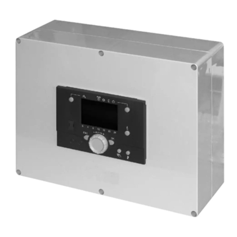
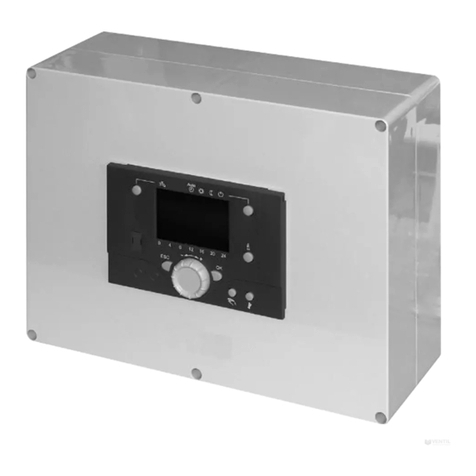
Ariston AST 100 Guide

SOLARcomfort
Solar Hot Water
Systems
AST 100 Solar
Controller
Installation,
Commissioning and User
Instructions
LEAVE THESE INSTRUCTIONS WITH THE
END USER
Country of Destination GB/IE

1
TABLE OF CONTENTS
1. GENERAL INFORMATION...............2
1.1 GUARANTEE ..........................................2
1.2 SYSTEM CONTENTS................................2
1.3 SYSTEM INSTRUCTION BOOKS ..................2
1.4 SOLARCOMFORT.................................3
1.5 LIFESTYLE ............................................3
1.6 HOW THE SYSTEM WORKS.......................3
2. SAFETY ...........................................4
3. TECHNICAL DATA ...........................6
3.1 COMPONENT LIST ..................................7
3.2 DIMENSIONS .........................................7
4. REGULATIONS & STANDARDS......8
4.1 WATER REGULATIONS .............................8
4.2 BUILDING REGULATIONS ..........................8
4.3 GENERAL GUIDANCE ...............................8
4.4 BRITISH & EUROPEAN STANDARDS ............9
4.5 UK REGULATIONS (WATER HEATING) ........9
4.6 UK REGULATIONS (CONSTRUCTION) .........9
4.7 EU DIRECTIVES ..................................10
4.8 OTHER PUBLICATIONS ...........................10
4.9 ELECTRICAL CONNECTION .....................10
4.10 THERMAL INSULATION ............................10
5. OPERATION & FUNCTIONS .........11
5.1 CONTROLLER LAYOUT ...........................11
5.2 CONTROLLER FUNCTIONS ......................12
5.3 MENU OPTION &VALUE DISPLAY ............12
5.4 MENU NAVIGATION ...............................12
5.5 CONTROLLER SETTINGS ........................13
5.6 SYSTEM IMAGE ....................................14
5.7 SYSTEM IMAGE ICONS ...........................14
5.8 TOOL BAR .........................................15
5.9 OPERATING MODE HND1 & HND2 ......16
5.10 CONTROLLER SETTINGS........................16
6. INSTALLATION...............................17
6.1 POSITIONING CONTROLLER....................17
6.2 WALL MOUNTING CONTROLLER ..............17
6.3 ELECTRICAL CONNECTIONS....................18
6.4 WIRING DIAGRAM STANDARD SYSTEM
ARR 1...............................................19
6.5 WIRING DIAGRAM SYSTEM WITH AUXILIARY
HEATING ARR 2 ..................................20
7. COMMISSIONING SYSTEM ..........21
7.1 INITIAL SETTING ...................................21
7.2 OPTIONS FOR STANDARD SYSTEM
ARR 1...............................................23
7.3 OPTIONS FOR SYSTEM WITH AUXILIARY HEAT
ARR 2...............................................24
7.4 INFORMATION ONLY MENU OPTIONS .........25
7.5 SETUP PARAMETERS MENU OPTIONS .......27
8. MAINTENANCE .............................32
8.1 FUSE REPLACEMENT.............................32
8.2 SENSOR FAILURE .................................32
8.3 CONTROLLER FAILURE ..........................32
8.4 FAULT FINDING ....................................32
9. USER INSTRUCTIONS .................35
9.1 CONTROLLER FUNCTIONS ......................35
9.2 MENU OPTION AND VALUE DISPLAY .........35
9.3 HOUSEHOLDER RESET OPTIONS .............35
9.4 HOW TO RESET COUNTERS ...................36
9.5 FAULT CONDITION ................................36

2
1. GENERAL
INFORMATION
This manual is an integral and essential part of the product. It should be
kept with the product.
Please read carefully the instructions and notes about SOLARcomfort
contained in this manual as they provide important information regarding
theinstallation, commissioninganduser instructionsof theAST 100 Solar
Controller and the SOLARcomfort system.
IMPORTANT
Failure to follow these instructions correctly may invalidate the
guarantee.
IMPORTANT
Solar domestic hot water heating systems must be installed to
comply with the current Building Regulations, British Standards
and any applicable local regulations refer to section 5.
The SOLARcomfort AST100 Solar Controller is guaranteed for 2 years -
see terms and conditions of guarantee on back page.
The complete SOLARcomfort solar water heating system is supplied in
the following consignments:-
1. 800201 Collector 1 per box
2. 3107024/5 Roof Fittings Kit 1cardboardtube
3. 3820011/2 System Components 1 box
4. 3820001 Tyfocor antifreeze heat transfer fluid
1 x 20l container
The following instruction booklets are supplied with a complete
SOLARcomfort solar water heating system:-
1. SOLARcomfort Solar HotWater Systems Collectors 2 & 3 Collector
Set.
Covers collector installation and plumbing connection.
Supplied in System Components box.
2. SOLARcomfort Solar Hot Water Systems Pump Group 40/60.
Covers installation, plumbingconnection, systemfilling,flushing and
commissioning.
Supplied in System Components box.
3. SolarController AST 100
Covers installation, wiring connection and User Instructions.
Supplied in System Components box.
1.1 GUARANTEE
1.2 SYSTEM CONTENTS
1.3 SYSTEM INSTRUCTION BOOKS

3
SOLARcomfort systems are highly efficient and provide cost savings on
the energy used for heating hot water wherever they are used in the UK.
However, the savings made will depend on local climate, installation
characteristics and the households use of hot water.
It is important that the SOLARcomfort system is correctly sized for the
local climate condition and the householders domestic hot water
requirements.
After installation of the SOLARcomfort system, changes to the
householders use of hot water will be beneficial. Simple changes such as
bathing in the evening instead of the morning, and putting automatic
washing machines on when free hot water is available by solar energy.
In addition the timing of the dwelling’s boiler controls must be modified to
ensure the‘hot water ON’time is set so that the water temperature in the
cylinder is at a minimum by the start of the ‘solar day’.
The solar collectors are heated by the sun’s rays. The heat generated is
storedinahotwaterstoragecylindere.g.anAristonPrimotwincoilstainless
steel cylinder. The AST 100 Solar Controller continually compares the
temperature of the water within the cylinder with the temperature of the
solarcollectors.
Wheneverthesolar collectorsarehotter thanthewater within thecylinder,
thecontroller switcheson thesystem’s circulating pump. The temperature
differential between the collectors and the cylinder is set via the AST 100
Solar Controller. The heat transfer fluid within the solar system is then
circulatedthroughthe collectors andthecylinder’sheat exchanger,heating
the cylinder in just the same way as a central heating boiler.
The cylinder typically has two coils (heat exchangers), the lower coil is
heated by the solar system, therefore solar is the primary heat source.
Theupper cylinder isheatedbyanauxiliary heatsource,typicallyacentral
heating boiler, which is used to heat water when there is insufficient heat
generated by the solar system. The Ariston Primo twin cylinder also has
twoimmersionheatersmaking itsuitablefor electriconly heating systems.
The SOLARcomfort system is a forced circulation sealed system and
therefore requires an expansion vessel and a pressure relief valve (PRV),
bothsupplied withSOLARcomfort.
Theairseparatormodulewithanintegralairventtogetherwithan automatic
air vent positioned at the highest point on the system ensures that the
sealed system remains free of air.
1.6 HOW THE SYSTEM WORKS
See fig. 1.6A
1.4 SOLARCOMFORT
1.5 LIFESTYLE

4
FIG. 1.6ASOLAR BASIC PRINCIPLES
Roof mounted collectors
(two collector system shown)
Pump group
Expansion
vessel
Solar system
low level fill
point
Ariston ITSI 210/300
twin coil cylinder
Upper coil
heated by boiler
or other heat
source
Lower coil heated by
solar energy
AST 100
Controller
Air vent
PRValve
Solar system
drain point
Temperature
Sensor S1
Temperature
Sensor S3
Temperature
Sensor S2 PRV discharge
vessel
Energy
Monitoring
Sensor S4
(option)

5
2. SAFETY WARNING
All wiring should be carried out to and comply with the current IEEWiring
Regulations.
All electrical work must comply with any relevant regulations that apply at
the time of the installation.
All electrical installation and maintenance of the AST 100 Controller must
be carried out by a competent qualified installer.
WARNING
TYFOCOR LS HeatTransfer Fluid.
Although non-toxic it should not be swallowed.
Refer to label on its container for storage and safety information.
A detailed technical specification is available from Ariston on request.
Caution
SOLARcomfort should be installed and commissioned by approved
contractors. Failure to do so may invalidate the warranty.
Caution
The controller should be positioned so that it is inaccessible to children
and cannot be tampered with.

6
3. TECHNICAL DATA CONTROLLER
Type AST100
Housing PC-ABS & PMMA
Dimensions 173 x 110 x 46
Mounting Wall (2 screws)
Operation 3 Push Buttons
Protection IP20 / DIN 40050
Environmental Temperature 0 - 40°C
FUNCTIONS
Temperature Differential Control Standard
Operating Hours Counter Standard
Energy Monitor Option
ELECTRICAL
Power Supply 210-240V
Electromechanical Relay 250V
Controller Mains Cable 1.0mm² 3 core heat resistant flex 3093y
Pump Cable (R1 and R2) 1.0mm² 3 core heat resistant flex 3093y
SENSORS
Collector Sensor S1
Cylinder lower S2
Cylinder upper S3
Energy monitor (collector return) S4

7
3.1 COMPONENT LIST
FIG. 3.1ACONTROLLER COMPONENT LIST
Listedbelow are allthe componentssuppliedwith theController.
Item Description Qty
1 Controller 1
2 Sensor- Collector 1
3 Sensor-Cylinder Upper 1
4 Sensor-Cylinder Lower 1
5 Spare Fuse -T4A 1
6 CableClips andscrews 4
7 FixingScrews 2
8 Wall Plug 2
FIG. 3.2ACONTROLLER DIMENSIONS
3.2 DIMENSIONS
47 110
11
13
173
130
155
104
==
HANGING
POINT
FIXING
POINT

8
4. REGULATIONS &
STANDARDS
SOLARcomfort hot water heating systems should be installed in
compliance with the following standards and regulations.
Water Supply (WaterFittings) Regulations 1999/ www.wras.co.uk
These regulations (bye-laws in Scotland) ensure a good supply of
wholesome water and that only approved materials, pipes and fittings are
used to convey water.
Theseare statutory documentsand take priority over all otherregulations
and recommendations. The installation of an unvented hot water storage
cylinderis classifiedas a“Controlled Service”and RegulationG3 applies.
To meet the requirements of the Regulations, installation of an unvented
system should be undertaken by a “competent installer”.
All installations of unvented hot water storage systems having a capacity
of more than 15 litres should be notified to the relevant Local Authority by
means of building notice or by the submission of full plans. It is important
to note that it is a criminal offence to install an unvented hot water storage
systemwithoutnotifyingtheLocalAuthority. Theinstallationoftheunvented
cylinder and hot water system must comply with BS 6700 and the HSE
Legionella Code of Practice.
Current guidance notes do not cover the connection of a solar thermal
circuit to an unvented storage vessel (cylinder). However, if guidance is
sought for compliance with current regulations the fundamental principle
is to provide a fail-safe means of shutting off the solar input to the heat
exchangerifthecylindertemperatureshould riseabovethesettemperature
of the cylinder’s energy cut out. (See Note 1).
As with all unvented hot water systems, notification of intention to install
should be given to your local building control.
Option A. A nonself-resettingmechanical shut-offshould be installedon
the solar primary flow to the cylinder. The mechanical shut-off should be
suitable for usewithasolar primarycircuit(i.e.high temperature andglycol
resistant). The mechanical shut-off should be integrated electrically with
thecylinder energycutout/s and ifnecessarythesolar circuittemperature
control, please refer to the solar controller manufacturer for further
information.
Option B. Where the solar controller and hydraulic system demonstrate
that by no lesser means the requirement in Option A is satisfied by other
means;certification by an approvals body is required to demonstrate that
in the event of the stored water going over temperature, the heat input to
the cylinder is isolated by physical means and is non self-resetting.
Thesesystems shouldbeclearlyidentifiedwith referencetotheapprovals
body. (See Note 2).
Note 1 : Whilst most solar cylinders use a coil type heat exchanger other
options such as external plate to plate devices, external annulars or‘tank
in tank’systems may be used but the same control options always apply.
Note 2 : Current approved bodies include the British Board of Agrèment
(BBA),WRc-NSF Limited, or KIWA.
4.1 WATER REGULATIONS
4.2 BUILDING REGULATIONS
4.3 GENERAL GUIDANCE

9
4.4 BRITISH & EUROPEAN
STANDARDS
Connection of thermal solar heating systems
EN 12976: Thermal solar heating systems and their components
(prefabricated systems).
ENV12977:Thermalsolarheatingsystem andtheircomponents(bespoke
systems).
BS5918:Latest version:Solar heating systems for domestic hot water.
Installation and equipment of DHW cylinders
BS5546:2000 Specification forinstallationofhotwater supplies fordomestic
purposes, using gas-fired appliances of rated input not exceeding 70 kW.
BS6700: 1997 Specification for design, installation, testing and
maintenance,of servicing,supplying waterfordomesticusewithinbuildings
and their curtilages.
The local water company by-laws.
Electrical connection
Current IEE wiring regulations.
Health and Safety document No 635 (Electricity atWork Regulations)
The Pressure Equipment Regulations (PED) 1999 - www.eurodyn.com
TheBuildingRegulations(L1A&B)2006andDomesticHeatingCompliance
Guide- www.communities.gov.uk
TheBuilding Regulations(P)2005 -www.communities.gov.uk
Controlof SubstancesHazardous to HealthRegulations (COSHH)1994-
www.hse.gov.uk
Further details available from:www.hse.gov.uk
Health & Safety At Work Act (HSW) 1974
Work at Height Regulations 2005.
Reportingof Injuries,Diseasesand DangerousOccurrences Regulations
(RIDDOR) 1995.
Management Health & Safety at Work Regulations (MHSWR) 1999.
Noise atWork Regulations 1989.
Construction (Health, Safety &Welfare) Regulations (CHSWA) 1996.
Electricity at Work Regulations 1989.
Construction Regulations (Head Protection) 1989.
Control of Substances Hazardous to Health Regulations (COSHH) 1994.
Construction (Design and Management) Regulations (CDM) 1994.
Personal Protective Equipment at Work Regulations 1992.
Lifting Operations and Lifting Equipment Regulations (LOLER) 1998.
Confined Spaces Regulations 1997.
Manual Handling Operations Regulations 1992.
TheWorkplace(Health,SafetyandWelfare) Regulations 1992(WHSWA).
Provision and Use ofWork Equipment Regulations (PUWER) 1998.
Healthand Safety(First Aid)Regulations 1981.
LZC - Low or zero carbon energy sources: strategic guide.
4.5 UK REGULATIONS
PARTICULARLY RELEVANT FOR
WATER HEATING EQUIPMENT
4.6 UK REGULATIONS
PARTICULARLY RELEVANT FOR
CONSTRUCTION

10
Further details available from: www.europa.eu.int
ConstructionDirective:89/106/EEC
Electromagnetic:89/336/EEC
Lowvoltage:73/23/EEC
MachineryDirective: 98/37/EC
Preventing hot water scalding in bathrooms:usingTMVs (IP 14/03).
DTI testing of solar systems (SP300275 1-3).
Review of issues related to active solar heating systems (SP300246).
Activesolar performanceanddata review(SP300270).
Solar heating systems for hot water (BS 5918).
Hardwater scalein hotwaterstorage cylinders(IP13/93).
Heating systems in buildings – design for water-based heating systems
(PrEN 12828).
Building log books (GPG 348).
Solar heating (CIBSE DBSPWGG).
Sun in Action II (ESTIF – Sun in Action II).
Minimising the risk of legionnaires’disease (TM 13).
BRE Digest 489.
EnergySavingTrust -www.est.org.uk
CE131 Solar Water Heating Systems - Guidance for professionals,
conventionalIndirect Models.
BS76712001Amended2004
APD P:
P1 - Design, Installation, Inspection andTesting
P2 - Provision of information
ThermalInsulation StandardTIMSA (ThermalInsulationManufacturersand
SuppliersAssociation).
4.7 EU DIRECTIVES
4.8 OTHER PUBLICATIONS
4.9 ELECTRICAL CONNECTION
4.10 THERMAL INSULATION

11
FIG. 5.1AAST 100 CONTROLLER
AST 100
°C
Indicator light
Backward
button
Set button
Display
Forward button
Cover retaining screw
Cable entry through
bottom only
Typical operating display for
standard system.
(The cylinder can be either a twin coil or
a single coil buffer type, controlled by
AST 100 Controller)
Arr 1 (default) Arr 2
5. OPERATION &
FUNCTIONS
Typical operating display for
system with auxiliary heat
source control.
(Upper coil shown only when it is
controlled by AST 100 Controller R2)
5.1 CONTROLLER LAYOUT

12
AST 100
5.2 CONTROLLER FUNCTIONS Indicator Light
Off No power to the SOLARcomfort controller.
Green Power is On - normal condition.
Red/Greenflashing Initialisationphase.
HND1 or HND2 are set to On.
Redflashing Fault condition. Indicates one of the sensors is
defective or not connected. Also a sensor symbol
on the display will flash rapidly indicating which
sensor is causing fault - see 5.7.
Thecontoller isoperatedby threepush buttonssituatedbelowthedisplay.
Forward Button
Use to scroll forward through menu options on the display.
Use to increase the value of a menu option when is displayed.
Backward Button
Use to scroll backward through menu options on the display.
Use to decrease value of a menu option when is displayed.
Set Button
Use to change and save, or zero menu option settings.
Menu Option
Displays the option selected using the forward and backward
buttons.
Value
Displays the current set value for the menu option selected.
When isalso displayeditindicates thatthe value canbe changed or
set to zero using the set button - refer to Section 5.5.
IMPORTANT
Menu options are set during commissioning and should not be
changed by the householder without first contacting the installer.
TheSOLARcomfort controllerhas two levelsofmenuoptions, information
only and setup parameters.
Whenpower is switchedonto the controlleritgoes through aninitialisation
phase and then shows the first of the‘infomation only’options (COL).
The forward and backward buttons can then be used to index
throughthe‘informationonly’options.
To access the‘setup parameters’use the forward button to reach the
last ‘infomation only’ option, then press and hold the forward button
until the first of the‘setup parameters’is shown (Arr).
The forward and backward buttons can then be used to index
throughthe‘setup parameters’.
BACKWARD
FORWARD
SET
INDICATOR
LIGHT
5.4 MENU NAVIGATION
5.3 MENU OPTION AND VALUE
DISPLAY
°C
Menu option
Value
Example shown menu option‘COL’

13
First
Information only options
Arr VERS
°C
FORWARDBACKWARD FORWARDBACKWARD
COL hP
Press
and hold
LastFirst Last
Set p parameters
The backward button indexes the options back from the ‘setup
parameters’through tothe‘infomation only’options. Fromhere the‘system
setup parameters’ has to be accessed again by pressing and holding the
forward button at the last‘display only’option.
FIG. 5.4AMENU NAVIGATION
5.5 CONTROLLER SETTINGS Tochange themenu optionsettings:-
1. Navigate to the required menu option - see above.
If the menu option can be changed or reset will also be
displayed.
TO CHANGE A VALUE
2. Press and hold set button until flashes.
3. The current setting will be displayed.
Record current value so value is not forgotten.
Pressforwardbuttontoincreasevalueorbackwardbuttontodecrease
value.
4. Press and hold set button again until stops flashing.
The new value will now be saved.
TO RESET A VALUE
2. Press and hold set button until flashes, the value will be reset
to 0.
3. To confirm press set again until it stops flashing.
To interrupt reset or change procedure, do not press any button for
about 5 seconds and the controller option will return to previous setting.
AST 100
BACKWARD
FORWARD
SET
INDICATOR
LIGHT
Menuoption
Value
Example shown menu option‘Arr’

14
5.7 SYSTEM IMAGE ICONS
Arr 1 shown
Collector(with sensor)
Cylinderwith heat exchanger
Cylindericon willeither show:-
one heater exchanger control when Arr 1 is selected, or
two heat exchanger controls when Arr 2 is selected.
Auxiliary heat source with burner symbol.
Only displayed when Arr 2 is selected.
Temperature Sensors
IconsforS1, S2 andS3 flash whenthe following optionsareselected from
the information only menu:-
Arr 1
S1 flashes when COL is selected - Collectortemperature
S2 flashes when TST is selected -Lowercylinder temperature
S3 flashes when S3 is selected - Uppercylindertemperature
Arr 2
S1 flashes when COL is selected - Collectortemperature
S2 flashes when TSTL is selected - Lower cylindertemperature
S3 flashes when TSTU is selected -Uppercylinder temperature
Whenicons flashrapidlyitindicates afault withtherelevant sensor,orthat
the sensor is not connected - consult engineer.
Arr 1 Arr 2
S1
S3
S2
5.6 SYSTEM IMAGE
Note:-
‘Arr’ is set on commissioning to
suit the installed system and
should not be changed - see 7.1.
FIG. 5.5ADISPLAY FOR S ETTINGS A RR 1 AND A RR 2
There are two operating displays for SOLARcomfort, which one is shown
depends on thesetting for setup parameter option ‘Arr’:-
1. Standard system for twin or single coil cylinders - Arr 1.
Only bottom coil is controlled by AST 100 (R1).
2. System with auxiliary heat source control - Arr 2.
Both coils are controlled by AST 100 (R1 & R2).
Typical operating display for
standard system
Arr 1 (default) Arr 2
Typical operating display for
system with auxiliary heat
source control

15
5.8 TOOL BAR The tool bar icons show the current system status.
nocIsutatSnoitacidnI
nOnOpmupralos-delbane1RyaleR
nOnOpmup.xua-delbane2RyaleR
nO dedeecxeerutarepmet'XMS'timilerotsmumixamteS
)f
fOsi'CERO'gniloocernehwylno(
gnihsalF nOottes'XCO'gniloocmetsyS
.eulavXMCtesotmetsysloocotgninnursipmupd
na
nOnOottes'FCO'noitcnufezeerfitnA
gnihsalF
.nOottes'CERO'noitcnufgnilooceR
dnanOsi'NCO'noitcnufpmetrotce
llocmuminiM-rO
pmetrotcellocmuminimteswolebsipmetrotcelloc
.'NMC'
rotcellocdnaNOottessi'FCO'noitcnufezee
rfitnA-rO
.'RFC'erutarepmetezeerfitnateswolebsi.pmet
gnihsalF
-:e.ievitcanwodtuhsytirucesrotcelloC
.dedee
cxeneebsah'ME'pmetrotcellocycnegremeteS
-:e.ievitcanwodtuhsytirucesrednilyC-rO
dedeecxeneebsah'XMS'pmet
rednilycmumixaM
gnihsalF oslanocirosnestnaveler,detcennoctonrotcefedrosneS
yldiparsehsalf
gnihsalFnOottes'
2DNH'ro'DNH'noitarepolaunaM
nO ottesrodegnahcebnaceulavnoitpounemdeyalpsiD
nottubtesgnisuorez
gnihsalF.eva
sotnottubtessserp,degnahcneebsaheulaV
SolarPump
Shown in pipework to collectors.
Flasheswhen solarpump is running(R1 On).
Auxiliary Heating Pump Arr 2 only
Shown in pipework to auxiliary heat source.
Flasheswhen auxiliarypump is running(R2 On).

16
5.10 CONTROLLER SETTINGS On power up the controller will go through an initialisation phase during
which the operating control light flashes red then green.
The controller then shows the system image display see 5.6.
To display menu options use forward button to scroll forward and back
button to scroll backwards.
Tochangethe menuoption settings:-
1. Pressforward buttontoscroll throughto requiredoption.
Ifthemenuoptioncanbechangedorreset will alsobedisplayed.
TOCHANGE AVALUE
2. Press and hold set button until flashes.
3. The current setting will be displayed.
Record current value so value is not forgotten.
Press forward button to increase value or back button to decrease
value.
4. Press and hold set button again until stops flashing.
The new value will now be saved.
TO RESET A VALUE
2. Press and hold set button until flashes, the value will be reset
to 0.
3. To confirm press again until it stops flashing.
To interrupt reset or change procedure, do not press any button for about
5 seconds and the counter will return to previous setting.
AST 100
BACK
FORWARD
SET
INDICATOR
LIGHT
Menu option
Value
Example shown menu option‘Arr’
5.9 OPERATING MODE HND1 &
HND2 When HND1 and/or HND2 are set to On or Off the following icons will be
displayed flashing
HND 1
Set to Auto - Normal operation.
Set to On - Relay R1 On - solar pump running - pump icon flashes.
Set to Off - Relay R1 Off - solar pump not running - pump icon not
flashing.
HND2
Set to Auto -Normaloperation.
Set to On - Relay R2 On - auxiliary heat pump running - pump icon
flashes.
Set to Off - Relay R2 Off - auxiliary heat pump not running - pump icon
not flashing.
Solar pump icon
Arr 1 Arr2
Auxiliary heat
source pump icon

17
Thepumpmoduleandairseparatormodulesshouldnormallybewallmounted
in close proximity to the cylinder.
Fig. 6.1A gives a typical layout.
TheAST100Solar Controller shouldbepositionedsothatthe householder
haseasy accesswithgood visibilityofthe display. Also, considerationhas
togiventoroutingfor connection tothepumpmodule,cylinder andcollector
temperaturesensors.
Cables supplied with the sensors and control unit are nominal length and
may require terminal boxes and extra cable lengths to make connections.
The controller should be positioned so that it is inaccessible to children
and cannot be tampered with.
6.1 POSITIONING CONTROLLER
6. INSTALLATION
6.2 WALL MOUNTING
CONTROLLER
The controller is wall mounted with two screws. The upper screw is used
to hang the unit on, the lower screw is used to fix the unit to the wall - see
fig.4.2A.
Two wall plugs and screws are supplied.
FIG. 6.1ASUGGESTED LOCATION
To Collector
Temperature
Sensor S1
From Collectors
To Collectors
AST 100
Controller
Cylinder
PRV
discharge
vessel
Fillpoint
Expansion
Vessel
Pump
Group
S3
S2

18
6:3 ELECTRICAL CONNECTIONS All wiring should be carried out to and comply with the current IEE
Wiring Regulations.
All electrical work must comply with any relevant regulations that
apply at the time of the installation.
All electrical installation and maintenance of SOLARcomfort must be
carried out by a competent qualified installer.
DO NOT drill casing for cable entry.
1. All cable sheath clamps must be correctly fitted.
2. The conductor sheaths must be continuous into joint enclosures.
3. Conductors must be correctly fastened to terminals.
4. Conductor insulation to be within 2mm of terminals.
5. All cable conductors external to joint enclosures must be insulated
and sheathed.
MAINS SUPPLY
The mains supply must be from a fused double pole isolating switch fitted
with 5 amp fuse or a BS1383/A kite marked domestic plug fitted with 5
amp fuse.
IMPORTANT
The mains supply cable must be separated from the sensor cables by
a minimum of 15mm.
ELECTROMECHANICALRELAYS
TheSOLARcomfortcontrollerincorporatestwostandardelectromechanical
relays which have a breaking capacity of 2(1)A 250V~.
AUXILIARY HEAT SOURCE PUMP
When the AST 100 is installed with an auxiliary heat source (and set as
Arr2), thepump for thisis wiredto the controller(R2) -see wiringdiagram
6.5B.
The auxiliary pump must not be set at maximum speed.
ARISTONPRIMOTWIN CYLINDERS
When using an Ariston Primo twin cylinder the following must be done:-
1. The lower cylinder temperature thermostat must be completely
removed.
2. The manual reset overheat thermostat must be wired as shown on
wiringdiagram Fig. 6.4A.
3. The AST 100 sensor S1 must be inserted into the cylinder’s lower
temperature sensor pocket together with the overheat temperature
sensor.
For other makes and models of cylinder, please refer to the
manufacturer’s instructions.
Note: All makes of cylinders with a
manualreset overheat thermostat
have to be connected in the same
way.

19
FIG. 6.4AWIRING DIAGRAM - STANDARD SYSTEM
12
S1
34
S2
56
S3
78
S4
Temp. Sensor
Pt1000
12
N
14 15 16 17
R2
18
NR1
20
NL
FUSE 4A
19
13
LN
SOLARcomfort P mp
(P mp Mod le)
brown
g/y
blue
brown
g/y
blue
brown
g/y
blue
g/y
g/y
blue
brown
blue
brown
FUSE 5A
Mains S pply
220-240V
Cylinder
S3 Upper
Sensor
S2 Lower
Sensor
S1 Collector
Sensor
Collector Collector
S4 Energy
Monitoring
Sensor (option)
BS 1383/A kite marked
Domestic Pl g - f sed 5A
or
Do ble Pole Isolating
Switch f sed 5A (as shown)
Cylinder
Man al Reset
Overheat
Stat NC
R1 2(1)A 220-240V~
1.0mm² 3 core heat resistant flex 3093y
1.0mm² 3 core
heat resistant
flex 3093y
1.0mm² 3 core
heat resistant
flex 3093y
6.4 WIRING DIAGRAM
STANDARD SYSTEM - Arr 1
Arr 1
IMPORTANT
The mains supply cable must be
separated from the sensor cables by a
minimum of 15mm.
Table of contents
Other Ariston Controllers manuals