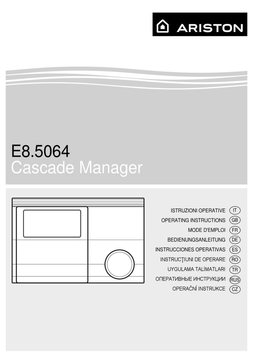
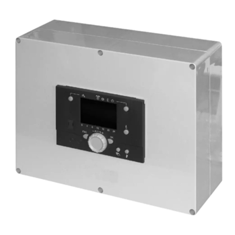
Ariston RVS 63 User manual

genuine original accessories
Istruzioni operative
Operating Instructions
RVS 63
CASCADE
MANAGER
3590475
420010550500 - 09/2013

2
GB
TABLE OF CONTENTS
Wall-mounting instructions ……………………………………………………………………………… pg. 3
Peripherals connection …………………………………………………………………………………… pg. 4
Product description…………………………………………………………………………………………… pg. 7
Management of zone control devices ……………………………………………………………… pg. 8
Electrical diagrams …………………………………………………………………………………………… pg. 10
Parameter setting …………………………………………………………………………………………… pg. 18
Temperature adjustment curve ………………………………………………………………………… pg. 20
Technical data …………………………………………………………………………………………………… pg. 21

3
GB
WALL-MOUNTING
INSTRUCTIONS
PRECAUTIONS
PRIOR TO INSTALLATION
The device is designed for wall-mounting.
Verify that all components are intact follow-
ing transport and handling, and have not
been damaged by knocks.
In case of evident damages to the product,
do not proceed with installation.
CAUTION
When drilling the wall, take care not to
damage any electrical wiring or existing
piping.
After identifying a suitable wall, be careful
not to damage any electrical wiring or exist-
ing piping and proceed as follows:
- Loosen the 6 screws on the temperature
adjuster body (Fig.1).
- Remove the cover (Fig.2).
- Position the temperature adjuster body
on the wall and mark the 4 fixing holes
(5mm)(Fig.3).
- Drill the 4 fixing holes.
- Secure the temperature adjuster body
using the wall plugs and screws provided.
- It is advisable to lay a cable tray (Fig.3a)
(which, once mounted, will conceal all
the cable outlets) near the cable outlets
on the device's body. Optimal cable tray
depth = 60 mm.
Prior to mounting the cable tray, drill
the latter in the area of the cable outlets
to facilitate insertion of the cables and
secure these with the cable clamp (Fig.
4).
- Once all the cables have been connected,
replace the cover from bottom to top
and secure it with the 6 screws so that
the bristle strip remains inside the
temperature adjuster body.
- Proceed with the initial start-up and
parameter setting of the and domestic
hot water production circuits, on the
basis of the parameter lists and system
requirements.
CAUTION
Before carrying out any work, disconnect
the power supply through the external bi-
polar switch.
ELECTRICAL CONNECTIONS
For greater safety, ask a qualified
technician to perform a thorough check of
the electrical system.
The manufacturer shall not be responsible
for any damage caused by the absence
of a suitable earthing system or by the
malfunctioning of the electricity mains
supply. Ensure that the electrical system
can provide the maximum power required
by the module (as indicated on the data
plate). Ensure that the wires have a suitable
cross-sectional area of at least 1.5 mm2.
Proper connection to an efficient earthing
system is essential for ensuring safe
operation of the device.
The power supply cable must be connected
to a 230 V-50 Hz network, while observing
the L-N poles and ensuring connection to
earth.
H05 V2V2-F
Important!
The connection to the mains must be
permanent (not using a plug) and equipped
with a bipolar switch with a contact air gap
of at least 3 mm when open.
Fig. 2
Fig. 3
Fig. 4
a
Fig. 1

4
GB
N
N
FLAME
L
L
BUS
TB
FLOOR
TA2
SE TNK SOL TA1
CN14
CN13
CN19
CN1
CN15
CN2 CN11
CN4
1
11
CN8
CN25
1
CN6
11
CN9
1
1
1
1
CN6
DL1
FT1
DL2
SW1
LPB
BUS
BTMB DB
PERIPHERALS CONNECTION
Connecting boilers to the control unit
The cascade interface PCB is used to
connect the RVS control unit to the boilers.
One cascade interface PCB must be used
for every boiler of the cascade (e.g. 3 boilers
with 3 interfaces).
A. boiler connection via BridgeNet BUS
B. RVS63 connection via LPB
C. LED
D. LED
E. micro-switches
CAUTION!
Prior to performing the electrical
connections or allocating the code,
disconnect the power supply to the boiler
and control unit.
Observe the polarities when performing
the connections.
Boiler address allocation
Every boiler communicates with the control
unit through the cascade interface PCB.
In the cascade operation (maximum 8
elements) it is necessary to allocate an
LPB (Siemens BUS) address to each boiler.
For the cascade to function properly,
a single address must be allocated to
each boiler through the corresponding
configuration of the “E” micro-switches on
the interface.
Refer to the adjacent figure for setting the
addresses.
IMPORTANT:
The identification numbers must be
entered in succession, always starting
from boiler number 1.
Diagnostics
• LEDs C and D OFF
cascade interface not connected
• LED C ON
cascade interface powered
• LED D flashing
LPB communication present
• LED D OFF
LPB communication absent
Connecting the cascade interface PCB to
the boiler
The cascade interface PCB is housed in the
boiler's instrument compartment.
Each PCB is connected to its boiler through
the Bridgenet BUS connection.
All cascade interface PCBs are connected
in parallel to the RVS control unit through
LPB.
+
-~
~
C10
C6
C2
R3
R46
R28
R31
Q4
R24A
C13
C1
R23
D2
Q3
IC8
C12
R45
IC7
IC5
DL1
R32
R5
R35
D6
R33
C11
R39
IC3
R22A
R22
IC9
R26
C14
R11
C16
R18
R36
Q6
R1
R30
Q2 R25
R49
R4
DZ1
C4
R21A
R27
C9
IC4
IC6
R20
R38
D4
D7
IC1
Q7 CN2
R6
R29
C5
D5
D3
CN4
R50
R23A
R16
FT1
R24
R43
C7
R9
C18
C3
DL2
C17
Q5
R13
CN5
R19
R12
R44
R48
R17
R34
R7
R14
R37
R2
R42
R40
R15
CN3
R41
RB1
Q1
R8
R47
SW1
X1
IC2
R21
C8
C19
IC10
D1
C15
R10
LPB
BUS
BTMB DB
AB
D
E
C
CASCADE
INTERFACE PCB
CASCADE
INTERFACE PCB
BOILER PCB
ON
caldaia nr. 1
ON
caldaia nr. 2
ON
caldaia nr. 3
ON
caldaia nr. 4
ON
caldaia nr. 5
ON
caldaia nr. 6
ON
caldaia nr. 7
ON
caldaia nr. 8
boiler no. 1 boiler no. 5
boiler no. 2 boiler no. 6
boiler no. 3 boiler no. 7
boiler no. 4 boiler no. 8

5
GB
QX4 QX3 N NQX4 FX4 EX2 QX2 NY6 Y5 NY2 Y1NQ6 NQX1 NQ2 NQ3 SK2 SK1 4 S3 T2 T1 L1NS3 L1 L1N
LPQRSTUTSUUZ N
n n n n n n k h f b b b anp p
M UX M BX4 M BX3 M H3 M B12 M BX2 M BX1 M B1 M H1 M B9 M B3 M MB DB XBD BSB
LPB
B2 G+ CL- CL+CL- CL+CL- CL+
N
N
FLAME
L
L
BUS
TB
FLOOR
TA2
SE TNK SOL TA1
CN14
CN13
CN19
CN1
CN15
CN2 CN11
CN4
1
11
CN8
CN25
1
CN6
11
CN9
1
1
1
1
CN6
DL1
FT1
DL2
SW1
LPB
BUS
BTMB DB
Once all connections to the control unit
have been effected, power the cascade
and verify whether the devices are properly
detected.
(If the control unit has a separate power
supply to the boiler, first power the control
unit then the boilers).
Verifying detection of cascade interface
PCB
After effecting all the connections, it is
necessary to verify whether the boiler has
identified the interface correctly.
ARISTON TOP MODELS
- Simultaneously press the back “ “ and
“OK” buttons until “Enter code“ appears
on the display.
- Turn the knob to enter the technical code
(234) then press OK; TECHNICAL AREA
will appear on the display.
Turn the knob and select:
- Full menu
Press the OK button.
Turn the knob and select:
- 0 Network
Press the OK button.
Turn the knob and select:
- 0.2 Bus network
Press the OK button.
Turn the knob to scroll the list and verify
that “Gateway LPB” appears among the
available devices
CHAFFOTEAUX TOP MODELS
- Press the OK button and “CODE” will ap-
pear on the display. Press the OK button.
- Turn the heating knob to enter the techni-
cal code (234) then press OK; the display
will visualise MENU.
Press the OK button.
Turn the knob and select:
- 0 Network
Press the OK button.
Turn the knob and select:
- 0.2 Bus network
Press the OK button.
Turn the knob to scroll the list and verify
that “22” appears among the available de-
vices.
RVS CONTROL UNIT
Press the OK button, press and hold the “
” button until the list of utility levels
appears.
Select the path:
Initial start-up > Cascade diagnostics
From the “Cascade diagnostics” menu it is
possible to verify which boilers are present
by checking the priorities allocated by the
control unit to each boiler and the current
status of parameters 8102 to 8116 (see
adjacent table).
Example: Boiler no. 1 present with priority
1, boiler no. 2 present with priority 2:
RVS
BUS BUS BUSLPB BUS LPB BUS BUS
LPB BUS
Parameter 8102 ≠ 0 Boiler No. 1 present
Parameter 8104 ≠ 0 Boiler No. 2 present
Parameter 8106 ≠ 0 Boiler No. 3 present
Parameter 8108 ≠ 0 Boiler No. 4 present
Parameter 8110 ≠ 0 Boiler No. 5 present
Parameter 8112 ≠ 0 Boiler No. 6 present
Parameter 8114 ≠ 0 Boiler No. 7 present
Parameter 8116 ≠ 0 Boiler No. 8 present
CASCADE
INTERFACE PCB
BOILER PCB
CONTROL UNIT TERMINAL
BOARD

6
GB
n k h f b b b an p
BX2 M BX1 M B1 M H1 M B9 M B3 M MB DB XBD BSB
LPB
B2 G+ CL- CL+CL- CL+CL- CL+
ZONA 3
(UNITÀ INTERNA P)
ZONA 2
(UNITÀ INTERNA 2)
ZONA 1
(UNITÀ INTERNA 1)
QAA 75 REMOTE CONTROL
The QAA 75 remote control allows for fully
managing the functions for the zone in
which it is installed, in addition to viewing
any anomalies which may occur. It can also
be used for room or climate control for
managing a heating circuit.
Positioning
The device detects the room temperature,
therefore several factors should be taken
into account when choosing an installa-
tion site. Position the device far from heat
sources (radiators, sunlight, fireplaces,
etc.) and from draughts, doorways and win-
dows which could affect the temperature
readings.
It should be installed approximately 1.5 me-
tres above the floor level.
Installation
In case of wall-mounting, sufficient space
must be left above the unit so that it can
be removed and slid back into place (Fig. 5).
Removing the unit from its base disconnects
the power supply, thus the unit stops
functioning.
The system will continue operating on the
basis of the parameters entered last.
CAUTION
Observe the polarities when performing the
connections.
Electrical connections
The low voltage and mains voltage
connections must be kept separate.
The device must be wired in conformity to
the requirements of the Class II protection
rating, namely the network and probe
cables must not pass through the same
cable tray.
14
25
3
connection terminals
2
CL-
1
CL+
ZONE 1
(INTERNAL UNIT 1)
ZONE 3
(INTERNAL UNIT P)
ZONE 2
(INTERNAL UNIT 2)

7
GB
PRODUCT DESCRIPTION
Buttons
1. DHW operating mode button
For activating domestic hot water
production
(bar on the display beneath the tap
symbol)
2. Heating circuit operating mode button
For setting 4 different heating operating
modes:
automatic clock-based: automatic
operation
based on time schedule
day 24 hours: heating with comfort
set-point
night 24 hours: heating with reduced
set-point
anti-freeze mode: heating
disengaged, anti-freeze function
activated.
3. Information button
For consulting information without
affecting temperature control, heating/
DHW operating status,
error signals
5. Room temperature control knob
For adjusting the room temperature
For selecting and modifying settings
during programming.
4. ESC button (4)
6. Confirm button (OK)
Both buttons are used together with
the - + knob for programming and
configuring the control unit.
Pressing ESC allows for accessing the
upper level each time; the modified
values are not restored.
For skipping to the next control level or
saving modified data,
press the OK button.
1.
2.
3.
4. 5. 6. 7. 8.
Xxxxxxxxxxxxxxxxxxxxxxxxxxx
ECOINFO
12
PROG
No.
7. Manual operation button
Pressing the button engages the
manual operating mode;
all pumps function, the mixing valve
is no longer controlled and the burner
is set to 60°C (the screwdriver symbol
appears on the display).
8. Chimney sweep function button
This button has no function.
Display
Heating with comfort set-point
Heating with reduced set-point
Heating with Frost protection
setpoint
Process running - wait
Burner in operation
Error signals
INFO Information level activated
PROG Programming activated
ECO Heating temporarily off; ECO
function active
Holiday function active
1 2
Heating circuit indicator
Manual mode
No. Command line number
(parameter number)
Basic visualisation
Press the OK button once.
Technical Area visualisation
press the OK button once
press the INFO button
until the menu list appears
- Turn the knob and select the desired
menu
- Confirm with the OK button
- Turn the knob and set the desired value
- Confirm with the OK button
- Press ESC to return to the basic
visualisation
- Turn the knob and select the desired
menu
- Confirm with the OK button
- Enduser
- Commissioning
- Engineer
- OEM (not configurable)
- Turn the knob and select the desired
parameter
- Confirm with the OK button
- Turn the knob and set the desired value
- Confirm with the OK button
- Press ESC to return to the basic
visualisation

8
GB
ZONE 1 ZONE 2 ZONE 3
QAA75 Room thermostat Room thermostat
Parameter 40 Internal unit 1 Parameter 5950 Optg mode
changeover HC2 Parameter 5960 Optg mode
changeover HCP
Parameter 42 Heating circuit 1 Parameter 5951 NC Parameter 5961 NC
Electrical connection CL+ / CL- Electrical connection H1 / M Electrical connection H3 / M
Room thermostat QAA75 Room thermostat
Parameter 5950 Optg mode
changeover HC1 Parameter 40 Internal unit 2 Parameter 5960 Optg mode
changeover HCP
Parameter 5951 NC Parameter 42 Heating circuit 2 Parameter 5961 NC
Electrical connection H1 / M Electrical connection CL+ / CL- Electrical connection H3 / M
Room thermostat Room thermostat QAA75
Parameter 5950 Optg mode
changeover HC1 Parameter 5960 Optg mode
changeover HC2 Parameter 40 Internal unit P
Parameter 5951 NC Parameter 5961 NC Parameter 42 Heating circuit 3
Electrical connection H1 / M Electrical connection H3 / M Electrical connection CL+ / CL-
QAA75 QAA75 Room thermostat
Parameter 40 Internal unit 1 Parameter 40 Internal unit 2 Parameter 5950 Optg mode
changeover HCP
Parameter 42 Heating circuit 1 Parameter 42 Heating circuit 2 Parameter 5951 NC
Electrical connection CL+ / CL- Electrical connection CL+ / CL- Electrical connection H1 / M
QAA75 Room thermostat QAA75
Parameter 40 Internal unit 1 Parameter 5950 Optg mode
changeover HC2 Parameter 40 Internal unit P
Parameter 42 Heating circuit 1 Parameter 5951 NC Parameter 42 Heating circuit 3
Electrical connection CL+ / CL- Electrical connection H1 / M Electrical connection CL+ / CL-
Room thermostat QAA75 QAA75
Parameter 5950 Optg mode
changeover HC1 Parameter 40 Internal unit 2 Parameter 40 Internal unit P
Parameter 5951 NC Parameter 42 Heating circuit 2 Parameter 42 Heating circuit 3
Electrical connection H1 / M Electrical connection CL+ / CL- Electrical connection CL+ / CL-
QAA75 QAA75 QAA75
Parameter 40 Internal unit 1 Parameter 40 Internal unit 2 Parameter 40 Internal unit P
Parameter 42 Heating circuit 1 Parameter 42 Heating circuit 2 Parameter 42 Heating circuit 3
Electrical connection CL+ / CL- Electrical connection CL+ / CL- Electrical connection CL+ / CL-
NOTE:
. Parameters 40 and 42 visible on remote control QAA 75
. Combinations possible even with 1 or 2 zones
. In systems with 3 zones it is necessary to use remote control QAA 75 for managing a zone.
MANAGEMENT OF ZONE CONTROL DEVICES

9
GB
Setting and operating mode of zone 1 and
zone 2 managed with Room Thermostat
- Press the heating circuit operating
mode button (2)
- Turn the knob (5) and select the desired
zone
- Press the OK button (6) to confirm
- Press the heating circuit operating
mode button (2) to select the desired
operating mode
- Press the OK button (6) to confirm
NOTE: it is necessary to have a heating
request (TA closed).
Setting and operating mode of zone 3
managed with Room Thermostat
(zone 3 enabled on parameter 5890 set to
“Heat circuit pump HCP Q20” value)
- Press the OK button (6) once
- Press the INFO button (3) until the
“menu list” appears
- Turn the knob (5) and select the
“Installateur” menu
- Press the OK button (6) to confirm
- Turn the knob (5) and select “heating
circuit P”
- Press the OK button (6) to confirm
- Turn the knob (5) and select the “1300
operating mode” parameter
- Press the OK button (6) to confirm
- Turn the knob (5) and select the desired
operating mode
- Press the OK button (6) to confirm
NOTE:
If zone management is performed via
remote control QAA75, the operating mode
must be set on the remote control itself.
1.
2.
3.
4. 5. 6. 7. 8.
TA
(ROOM THERMOSTAT) TA
(ROOM THERMOSTAT)
ZONE 1
(INTERNAL UNIT 1
QAA75) ZONE 2
(INTERNAL UNIT 2
QAA75) ZONE 3
(INTERNAL UNIT P
QAA75)
n
n n n n k h f b b b anp p
M
BX4 M BX3 M H3 M B12 M BX2 M BX1 M B1 M H1 M B9 M B3 M MB DB XBD BSB
LPB
B2 G+ CL- CL+CL- CL+CL- CL+

10
GB
QX4 QX3 N NQX4 FX4 EX2 QX2 NY6 Y5 NY2 Y1NQ6 NQX1 NQ2 NQ3 SK2 SK1 4 S3 T2 T1 L1NS3 L1 L1N
LPQRSTUTSUUZ N
n n n n n n k h f b b b anp p
M UX M BX4 M BX3 M H3 M B12 M BX2 M BX1 M B1 M H1 M B9 M B3 M MB DB XBD BSB
LPB
B2 G+ CL- CL+CL- CL+CL- CL+
B9
OUTDOOR PROBE RVS
CASCADE MANAGER
B2
MANIFOLD
PROBE
(T2 - T1)
BOILER 1
CONNECTION
(QX4 - FX4)
BOILER 2
CONNECTION
RVS
B9
B2
TA
COMPENSATOR
TA
GENERIC BOILERS DIAGRAM
MENU PARAMETER DESCRIPTION VALUE
Engineer
Configuration 5770 Source type 2x1 cascade
Engineer
Configuration 5894 Relay output QX4 Heat request K27
Engineer
Configuration 5950 Function input H1 Optg mode changeover HC1

11
GB
QX4 QX3 N NQX4 FX4 EX2 QX2 NY6 Y5 NY2 Y1NQ6 NQX1 NQ2 NQ3 SK2 SK1 4 S3 T2 T1 L1NS3 L1 L1N
LPQRSTUTSUUZ N
n n n n n n k h f b b b anp p
M UX M BX4 M BX3 M H3 M B12 M BX2 M BX1 M B1 M H1 M B9 M B3 M MB DB XBD BSB
LPB
B2 G+ CL- CL+CL- CL+CL- CL+
B9
OUTDOOR PROBE RVS
CASCADE MANAGER
BX1
MANIFOLD
PROBE
BUS
BOILER
CONNECTION
RVS
B9
BX1
BUS BUS
LPB
COMPENSATOR
BUS BUS
LPB
BRIDGENET BUS BOILERS DIAGRAM
MENU PARAMETER DESCRIPTION VALUE
Engineer
Configuration 5950 Function input H1 Optg mode changeover HC1

12
GB
RVS
B9
BX1
BUS BUS
LPB
COMPENSATOR
BUS BUS
LPB
Q3
QX1
ZONE 3
Q6
ZONE 2
Q6
ZONE 2
CIRCULATION PUMP
+-+-
Y5/Y6 B12
B1
Y1/Y2
Y5 (+)/Y6(-)
ZONE 2
MIXING VALVE
Q2
ZONE 1
Q2
ZONE 1
CIRCULATION PUMP
Q3
STORAGE CYLINDER
CIRCULATION PUMP
VNR
B3
QX1
ZONE 3
CIRCULATION PUMP
QX4 QX3 N NQX4 FX4 EX2 QX2 NY6 Y5 NY2 Y1NQ6 NQX1 NQ2 NQ3 SK2 SK1 4 S3 T2 T1 L1NS3 L1 L1N
LPQRSTUTSUUZ N
n n n n n n k h f b b b anp p
M UX M BX4 M BX3 M H3 M B12 M BX2 M BX1 M B1 M H1 M B9 M B3 M MB DB XBD BSB
LPB
B2 G+ CL- CL+CL- CL+CL- CL+
B9
OUTDOOR PROBE
RVS
CASCADE MANAGER
BX1
MANIFOLD
PROBE
B12
ZONE 2 PROBE
B1
ZONE 1 PROBE
B3
STORAGE CYLINDER
PROBE
Y1(+)
Y2(-)
ZONE 1
MIX
BUS
BOILER
CONNECTION
BRIDGENET BUS BOILER DIAGRAM 1 DIRECT ZONE, 2 LOW TEMPERATURE ZONES
AND DOMESTIC HOT WATER STORAGE CYLINDER
MENU PARAMETER DESCRIPTION VALUE
Engineer
Configuration 5715 Heating circuit 2
(zone 2 activation) On
Engineer
Configuration 5890 Relay output QX1
(activation of zone 3 management) Heat circuit pump HCP Q20

13
GB
B9
OUTDOOR PROBE
BX1
MANIFOLD
PROBE
B3
STORAGE CYLINDER
PROBE
BUS
BOILER
CONNECTION
Q6
ZONE 2
CIRCULATION PUMP
Q2
ZONE 1
CIRCULATION PUMP
Q3
STORAGE CYLINDER
CIRCULATION PUMP
QX1
ZONE 3
CIRCULATION PUMP
RVS
B9
BX1
BUS BUS
LPB
COMPENSATOR
BUS BUS
LPB
Q3
Q2
ZONE 1
Q6
ZONE 2
QX1
ZONE 3
VNR
B3
QX4 QX3 N NQX4 FX4 EX2 QX2 NY6 Y5 NY2 Y1NQ6 NQX1 NQ2 NQ3 SK2 SK1 4 S3 T2 T1 L1NS3 L1 L1N
LPQRSTUTSUUZ N
n n n n n n k h f b b b anp p
M UX M BX4 M BX3 M H3 M B12 M BX2 M BX1 M B1 M H1 M B9 M B3 M MB DB XBD BSB
LPB
B2 G+CL- CL+CL- CL+CL- CL+
RVS
CASCADE MANAGER
BRIDGENET BUS BOILER DIAGRAM 3 DIRECT ZONES
AND DOMESTIC HOT WATER STORAGE CYLINDER
MENU PARAMETER DESCRIPTION VALUE
Engineer
Configuration 5715 Heating circuit 2
(zone 2 activation) On
Engineer
Configuration 5890 Relay output QX1
(activation of zone 3 management) Heat circuit pump HCP Q20

14
GB
RVS 1
B9
BX1
BUS BUS
LPB
COMPENSATOR
BUS BUS
LPB
RVS 2
Q3
QX1
ZONE 3
Q6
ZONE 2
Y5/Y6 B12
B1
Y1/Y2
Q2
ZONE 1
QX1
ZONE 6
Q6
ZONE 5
Y5/Y6
B12
B1
Y1/Y2 Q2
ZONE 4
VNR
B3
BRIDGENET BUS BOILER DIAGRAM 2 DIRECT ZONES, 4 LOW TEMPERATURE ZONES
AND DOMESTIC HOT WATER STORAGE CYLINDER
RVS 2 MENU PARAMETER DESCRIPTION VALUE
Engineer
Configuration 5715 Heating circuit 2
(zone 5 activation) On
Engineer
Configuration 5890 Relay output QX1
(activation of zone 6 management) Heat circuit pump HCP Q20
Engineer
LPB 6600 Device address 2
Engineer
LPB 6640 Clock mode Slave without remote setting
RVS 1 MENU PARAMETER DESCRIPTION VALUE
Engineer
Configuration 5715 Heating circuit 2
(zone 2 activation) On
Engineer
Configuration 5890 Relay output QX1
(activation of zone 3 management) Heat circuit pump HCP Q20

15
GB
Q6
ZONE 5
CIRCULATION PUMP
Q2
ZONE 4
CIRCULATION PUMP
QX1
ZONE 6
CIRCULATION PUMP
Q6
ZONE 2
CIRCULATION PUMP
Q2
ZONE 1
CIRCULATION PUMP
Q3
STORAGE CYLINDER
CIRCULATION PUMP
QX1
ZONE 3
CIRCULATION PUMP
+-+-
Y5 (+)/Y6(-)
ZONE 2
MIXING VALVE
+-+-
Y5 (+)/Y6(-)
ZONE 2
MIXING VALVE
QX4 QX3 N NQX4 FX4 EX2 QX2 NY6 Y5 NY2 Y1NQ6 NQX1 NQ2 NQ3 SK2 SK1 4 S3 T2 T1 L1NS3 L1 L1N
LPQRSTUTSUUZ N
n n n n n n k h f b b b anp p
M UX M BX4 M BX3 M H3 M B12 M BX2 M BX1 M B1 M H1 M B9 M B3 M MB DB XBD BSB
LPB
B2 G+ CL- CL+CL- CL+CL- CL+
RVS 2
CASCADE MANAGER
B12
ZONE 5 PROBE
B1
ZONE 4 PROBE
QX4 QX3 N NQX4 FX4 EX2 QX2 NY6 Y5 NY2 Y1NQ6 NQX1 NQ2 NQ3 SK2 SK1 4 S3 T2 T1 L1NS3 L1 L1N
LPQRSTUTSUUZ N
n n n n n n k h f b b b anp p
M UX M BX4 M BX3 M H3 M B12 M BX2 M BX1 M B1 M H1 M B9 M B3 M MB DB XBD BSB
LPB
B2 G+ CL- CL+CL- CL+CL- CL+
B9
OUTDOOR PROBE RVS 1
CASCADE MANAGER
BX1
MANIFOLD
PROBE
B12
ZONE 2 PROBE
B1
ZONE 1 PROBE
B3
STORAGE CYLINDER PROBE
BUS
BOILER
CONNECTION
Y1(+)
Y2(-)
ZONE 1
MIXING VALVE
Y1(+)
Y2(-)
ZONE 1
MIXING VALVE

16
GB
Q3
STORAGE CYLINDER FILLING
CIRCULATION PUMP
Q3
STORAGE CYLINDER
CIRCULATION PUMP
QX4 QX3 N NQX4 FX4 EX2 QX2 NY6 Y5 NY2 Y1NQ6 NQX1 NQ2 NQ3 SK2 SK1 4 S3 T2 T1 L1NS3 L1 L1N
LPQRSTUTSUUZ N
n n n n n n k h f b b b anp p
M UX M BX4 M BX3 M H3 M B12 M BX2 M BX1 M B1 M H1 M B9 M B3 M MB DB XBD BSB
LPB
B2 G+ CL- CL+CL- CL+CL- CL+
B9
OUTDOOR PROBE RVS
BOILER CONNECTION
BX1
MANIFOLD
PROBE
B3
STORAGE CYLINDER PROBE BUS
BOILER
CONNECTION
RVS
B9
BX1
BUS BUS
LPB
COMPENSATOR
BUS BUS
LPB
Q3
Q3
VNR
B3
BRIDGENET BUS BOILER DIAGRAM
EXTRA - HYDRAULIC UNIT FOR FILLING THE STORAGE CYLINDER
MENU PARAMETER DESCRIPTION VALUE
-- -- -- -- --

17
GB
Q3
STORAGE CYLINDER
CIRCULATION PUMP
QX2
RECIRCULATION
CIRCULATION PUMP
QX4 QX3 N NQX4 FX4 EX2 QX2 NY6 Y5 NY2 Y1NQ6 NQX1 NQ2 NQ3 SK2 SK1 4 S3 T2 T1 L1NS3 L1 L1N
LPQRSTUTSUUZ N
n n n n n n k h f b b b anp p
M UX M BX4 M BX3 M H3 M B12 M BX2 M BX1 M B1 M H1 M B9 M B3 M MB DB XBD BSB
LPB
B2 G+ CL- CL+CL- CL+CL- CL+
B9
OUTDOOR PROBE RVS
CASCADE MANAGER
BX2
RECIRCULATION
PROBE
BX1
MANIFOLD PROBE
B3
STORAGE
CYLINDER PROBE
BUS
BOILER
CONNECTION
RVS
CASCADE MANAGER
B9
OUTDOOR PROBE
BX1
MANIFOLD
PROBE
BUS BUS
LPB
COMPENSATOR
BUS BUS
LPB
Q3
STORAGE
CYLINDER
CIRCULATION PUMP
VNR
B3
STORAGE CYLINDER PROBE BX2
RECIRCULATION
PROBE
QX2
RECIRCULATION
CIRCULATION PUMP
BRIDGENET BUS BOILER DIAGRAM
EXTRA - DHW RECIRCULATION
MENU PARAMETER DESCRIPTION VALUE
Engineer
Configuration 5891 Relay output QX2
(recirculation pump activation) Circulating pump Q4
Engineer
Configuration 5931 Input probe BX2
(recirculation probe activation) DHW circulation sensor B39

18
GB
MENU PARAMETER DESCRIPTION
RANGE
VALUE
Engineer
Heating circuit 1
(ZONE 1)
710 Heating circuit 1 Comfort setpoint 16-35°C 20°C
712 Heating circuit 1 Reduced setpoint 16-35°C 16°C
714 Heating circuit 1
Frost protection setpoint 4-16°C 10°C
720 Heating circuit 1
Heating curve slope 0.10-4.00 1.50
721 Heating circuit 1
Heating curve displacement -4.5 - 4.5°C 0.0
730 Heating circuit 1
Summer/winter heating limit
- - -°C - 30.0°C
(--- = deactivated) 20.0°C
740 Heating circuit 1
Flow temp setpoint min 8°C at par. 741 8°C
741 Heating circuit 1
Flow temp setpoint max par. 740 at 95°C 80°C
Engineer
Heating circuit 2
(ZONE 2, only if
active)
1010 Heating circuit 2 Comfort setpoint 16-35°C 20°C
1012 Heating circuit 2 Reduced setpoint 16-35°C 16°C
1014 Heating circuit 2
Frost protection setpoint 4-16°C 10°C
1020 Heating circuit 2
Heating curve slope 0.10-4.00 1.50
1021 Heating circuit 2
Heating curve displacement -4.5 - 4.5°C 0.0
1030 Heating circuit 2
Summer/winter heating limit
- - -°C - 30.0°C
(--- = deactivated) 20.0°C
1040 Heating circuit 2
Flow temp setpoint min 8°C at par. 1041 8°C
1041 Heating circuit 2
Flow temp setpoint max par. 1041 at 95°C 80°C
Engineer
3/P heating circuit
(ZONE 3, only if
parameter 5890 is
active)
1310 Heating circuit 2 Comfort set-point 16-35°C 20°C
1312 Heating circuit 3 Reduced set-point 16-35°C 16°C
1314 Heating circuit 3
Frost protection setpoint 4-16°C
1320 Heating circuit 3
Heating curve slope 0.10-4.00 1.50
1321 Heating circuit 3
Heating curve displacement -4.5 - 4.5°C 0.0
1330 Heating circuit 3
Summer/winter heating limit
- - -°C - 30.0°C
(--- = deactivated) 20.0°C
1340 Heating circuit 3
Flow temp setpoint min 8°C at par. 1341 8°C
1341 Heating circuit 3
Flow temp setpoint max par. 741 at 95°C 80°C
Engineer
DHW
(Storage cylinder)
1610 Nominal setpoint par. 1612 at 65°C 55°C
1612 Reduced setpoint from 8°C par. 1610 40°C
Engineer
1640 Legionella function
- Off
- Periodically
(x =
days: par. 1641)
- Fixed weekday
(
par. 1642)
OFF
1641 Legionella funct periodically
(parameter 1640: periodic) 3 days 3 days
1642 Legionella funct weekday
(parameter 1640: fixed day) Monday... Sunday Monday
PARAMETER SETTING

19
GB
MENU PARAMETER DESCRIPTION
RANGE
VALUE
Engineer
DHW
(Storage cylinder)
1644 Legionella funct time
(function start time) --:--
1645
Legionella funct setpoint
(temperature at end of anti-Legionnaire's
disease function)
55-95°C 65°C
1646 Legionella funct duration
(maximum Legionella funct duration) --- ÷ 360nw 10 min
1647
Legionella funct circ pump
(DHW recirculation pump activation
during function)
On - Off On
Engineer
DHW
(Storage cylinder)
1620
Time program release
(this parameter sets the DHW storage
cylinder management according to the
following selection:
- 24h/day > always active
- Time programs HCs > follows the
heating time program
- Time program 4/DHW > dedicated time
schedule)
- 24h/day
- Time programs
HCs
- Time program
4/DHW
Time program 4/DHWl
1630
Charging priority
(Manages the Storage Cylinder priority
according to the following selection:
-Absolute > heating deactivated
- Shifting > when the generator's heat
output is no longer sufficient, the mixed
circuit and direct circuit are switched
off until storage cylinder filling is
completed
- None > storage cylinder simultaneous
to heating
-MC shifting, PC absolute. > the direct
circuits remain blocked until filling of
the DHW storage cylinder is completed.
When the generator's heat output is no
longer sufficient, the mixing circuits are
also limited.)
- Absolute
- Shifting
- None
- MC shifting, PC
absolute
MC shifting, PC absolute
Engineer
Cascade
3540
Auto kilde.sekv.omkobling
(switching time of the boiler ignition sequence.
By setting the “---” the ignition sequence
is fixed.
The first boiler of the sequence is settable
through parameter 2544)
10-990h
500h
3544
Leading source
(first boiler of the fixed sequence see
parameter 3540)
- Source 1
- Source 16
Engineer
DHW storage 5020
Flow setpoint boost
Manifold temperature increase during
heating up of the storage cylinder.
The system takes as reference the set
storage cylinder temperature that must be
added to the present parameter
E.g.: Nominal set-point (par. 1610) = 60°C
(par. 5020) = 15°C
60 + 15 = 75°C
This means that during heating up of the
storage cylinder the manifold operates at 75°C
0 - 30°C
16°C
Engineer
Configuration 6205
Reset to default parameters
(restores the parameters to the default
settings)
yes - no
no

20
GB
100
4 3,5 3 2,75 2,5 2,25
°C 2
1,75
1,5
1,25
1
0,75
0,5
0,25
90
80
70
60
50
40
30
20 10 0 -10 -30-20 °C
TEMPERATURE ADJUSTMENT CURVE
Characteristic curve
The heating curve is used to determine the
flow set-point on the basis of which the flow
temperature can be adjusted in relation to
the existing atmospheric conditions. The
heating curve can be adjusted with various
parameters, so that the device's power -
and thus the room temperature - can be
adapted to personal needs.
Heating curve slope
The slope of the heating curve determines
the flow temperature variation in relation to
the outdoor temperature.
If the room temperature varies with cool
outdoor temperatures but not with warm
temperatures, the slope must be corrected.
Increase the setting:
the flow temperature increases especially
with low outdoor temperatures.
Reduce the setting:
the flow temperature decreases especially
with low outdoor temperatures.
Heating curve displacement
The parallel displacement of the
characteristic curve modifies the flow
temperature in a uniform manner along the
entire outdoor temperature range. If the
room temperature is generally too warm
or too cold, it must be corrected through a
parallel displacement of the curve.
Curve adaptation
With the adaptation function, the
temperature adjuster
automatically adjusts the characteristic
curve to the existing conditions.
The correct slope and parallel displacement
become irrelevant.
The adaptation can only be set to active or
deactivated
To ensure correct operation, observe the
following rules:
• a room temperature probe must be
installed;
• the “Room influence” setting must range
between 1 and 99;
• in the reference room (where the room
temperature probe is installed) there should
not be any thermostatic valves for radiators
(any valves present must be fully opened).
MENU PARAMETER DESCRIPTION VALUE
Heating circuit 1
(ZONE 1)
720 Heating curve slope 1.5
721 Characteristic Heating curve
displacement 0.0
Heating circuit 2
(ZONE 2, only if active)
1020 Heating curve slope 1.5
1021 Characteristic Heating curve
displacement 0.0
3/P heating circuit
(ZONE 3, only if parameter
5890 is active)
1320 Heating curve slope 1.5
1321 Characteristic Heating curve
displacement 0.0
Table of contents
Languages:
Other Ariston Controllers manuals
Popular Controllers manuals by other brands

Toshiba
Toshiba V Series user manual

Panasonic
Panasonic AWRP605 - CCU & PAN/TILT CONTR operating instructions

Danfoss
Danfoss Old ICAD 600 series instruction manual

EuroLite
EuroLite LED LMCTC user manual

Morningstar
Morningstar SUNSAVER DUO Installation and operation manual

Vention
Vention MachineMotion V1E0 Safety guide