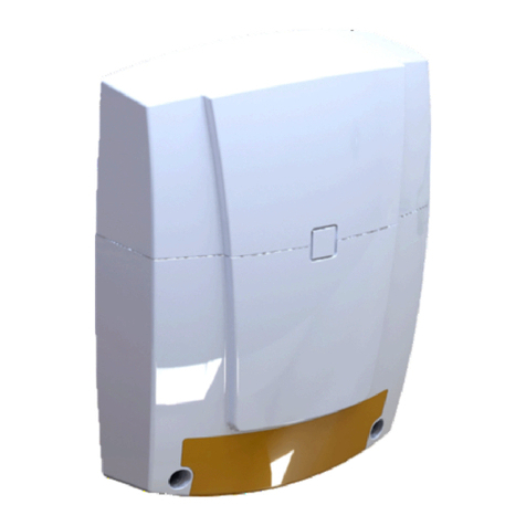
Aritech AS280G3 Assembly instructions

© 2023 Carrier 1 / 16 P/N PAK200953-ML • REV F • ISS 12JAN23
AS280G3 Internal Siren Installation Sheet
EN
FR
NL
1
2
3
4
5
EN: Installation Sheet
Operation
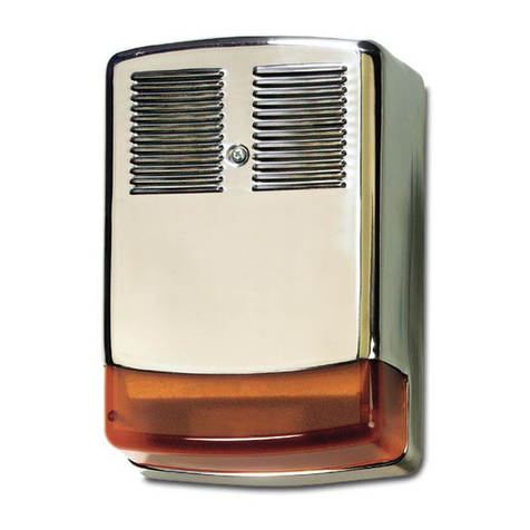
AS280G3 Internal Siren is used for notification of an alarm
condition as generated within an intruder, hold-up or other
alarm system. In response to commands from the alarm
system control panel, the AS280G3 will emit a high intensity
sound.
AS280G3 will detect any attempt to gain unauthorised access
to the sounder by removal of the cover, or any attempt to
remove it away from its mounting surface. This will generate a
Tamper (Auto-protection) signal which is normally fed back to
the alarm control panel. Integrity of the Trigger Command
(1)
(2)(1)
(3) (3)
(3) (3)
(5)
(4)
(6)
(11) CP
4K7
(5) (7) TMP
−
+
(3)AUX+
(4) 0V
(6) TMP IN
(9)Alarm−
(10) PROG OUT
(10) PROG OUT
(8) FLT IN
(8) FLT IN
BAT+
BAT−
ALIM+
ALIM−
AP(S)
AP(R)
FAUTE
FAUTE
BL+
ING
TEST
AS280G3
(1)
(2)
(13)AS280G3 (EOL)(12)AS280G3
ALIM+
ALIM−
AP(S)
AP(R)
FAUTE
FAUTE
BL+
ING
TEST
ALIM+
ALIM−
AP(S)
AP(R)
FAUTE
FAUTE
BL+
ING
TEST
(11) CP
4K7
(5)
(3)AUX+
(4) 0V
(6) TMP IN
(9)Alarm−
(10) PROG OUT
(8) FLT IN
(8) FLT IN
(10) PROG OUT
(7) TMP
(11)ATSx500A
(7) TMP
−
+
(3)AUX+
(4) 0V
(6) SIR TMP
(9) SIR. S1
(10) OUTPUT n
(10) OUTPUT n
(8) INPUT n
(8) INPUT C
BAT+
BAT−
ALIM+
ALIM−
AP(S)
AP(R)
FAUTE
FAUTE
BL+
ING
TEST
AS280G3
(1)
(2)
4K7 4K7
4K7
1K

2 / 16 P/N PAK200953-ML • REV F • ISS 12JAN23
(Ring Line) connection is constantly monitored and will cause
the unit to self-activate (if SAD mode selected) and generate a
Tamper signal to the control panel if loss of connection is
detected.
AS280G3 is classified as a self-powered sounder.
Note: BS122N battery should be purchased separately.
The battery can be recharged via the external power source.
This battery is used to operate the sounder if the external
power is removed. AS280G3 can be configured to self-activate
(SAD Mode ON) in the event that a Tamper condition is
detected and will always self-activate if the external power is
removed.
AS280G3 self-test, to check the integrity of its on-board battery
and battery charging circuit, is performed every 24 hours. If an
error condition is detected, a Fault (Faute) signal is generated.
This is normally connected back to the control panel. This self-
test can be triggered at any time by a Remote Test command
sent from the control panel. An on-board diagnostic LED
provides visual indication of Battery or Charger status.
To assist with commissioning, AS280G3 has an Engineer
Mode to provide silent start-up and audible confirmation to
indicate the correct closure of the tamper detection switches
and correct battery connection.
Features
•High efficiency operation
•Silent engineer start-up
•Selectable sound cut off timer
•Selectable SAB (SAD) mode
•Front and rear tamper
•Battery circuit protection with resettable fuse
•Diagnostic LED
•Battery test with fault output
•Remote test input
•Ring line monitoring
•Microprocessor controller
•Enclosed electronics module
•Audible tamper status to assist with commissioning
•Break-out rear tamper section for easy installation
Note: In accordance with Grade 3 requirements, the siren
tamper output is triggered when the siren detects:
•Sounder + power supply (ALIM+) cut
•0 V power supply cut
Caution: Do not connect the ALIM+ power supply to AUX+
power supply of the control panel, which disconnects during a
mains fault. It must be connected to a permanent + power
supply.
Functional information
Tamper circuit for single or multiple cascade installations
The AS280G3 sounder provides a tamper (Auto-protection)
circuit for both single (Figure 3) and multiple cascade
installations (Figure 4). In cascade installations with two or
more sounders, from the end-of-line sounder, moving back
towards the control panel, AP(R) of the sounder is connected
to AP(S) of the previous cascade sounder. Cascade units must
also have the white CASC link cut. Do not cut the CASC link
on the end-of-line sounder.
Engineer Mode (“ING”)
Selects silent start-up and silent maintenance. The Engineer /
ENG (ING) input may be brought back to the control panel and
connected to a programmable output (or manually connected
to ALIM+). Switching this control panel output high when
maintenance is required will prevent the sounder from self-
activating when the cover is removed or BL+ activated. The
Tamper output is open when ENG mode is activated, this
prevents inadvertent system setting.
Self-test and Fault output
The AS280G3 sounder performs a self-test every 24 hours.
This function tests the condition of the battery. If a fault is
found the Fault (Faute) output will open. The fault source can
be identified using the Diagnostic LED (see “Diagnostics” on
page 4). This is ONLY enabled when the cover is opened
(cover tamper active) for longer than 2 s, and the TEST input is
low or not connected.
The Fault output will be cleared (output closed) when:
•The fault has been cleared, for example, battery
connected
•The fault has been cleared and the sounder performs a
self-test (Remote input or 24-hour self-test)
•The fault has been cleared, and both ALIM+ and the
battery has been disconnected / reconnected,
—or —
TEST connected to ALIM+ to initiate self-test.
Remote Test
With the cover closed, taking the Remote Test/REM (TEST)
input high will force a self-test (ING input low or not
connected). The Fault output is immediately opened to
acknowledge receipt of the Remote Test command. The
battery is immediately tested. Any fault found will be indicated
by the Fault output remaining open after 25 s. The Fault output
will remain open until the fault has been cleared and another
Self-Test or Remote Test has been performed. If the self-test
has passed, the Fault output will close after 25 s from starting
the Remote Test.
Options selection
Table 1 below summarises the link options for various modes
of operation.
Table 1: Option selection links
BL INHIBIT** (BLi)
(Sound Trigger Inhibit-Off)
+ve*
None
FL INHIBIT** (FLi)
(Strobe Trigger Inhibit-Off)
+ve*
None
SAD (self-activation on
tamper detection)
On*
Off
Sound Cut-Off Timer
5 s***
90 s
3 min
15 min*
T1
T2
Link fitted Link NOT fitted
* Factory default setting.
** When BL INHIBIT link is fitted, BL+ cut line detection will not
report a Tamper to the control panel, however, it will still activate.

P/N PAK200953-ML • REV F • ISS 12JAN23 3 / 16
*** This cut-off time option intended for installation purposes only.
Hold Off Facility for Sound (BL+) Trigger Inputs
A Hold Off facility is provided by links Blocage/BL INHIBIT
(BLi) to enable triggering of the sounder from a control panel
configured for positive hold-off signalling (see Table 1 on page
2).
BLi connects internal pull-down resistors to the BL+ trigger
input. When the links is FITTED, an ALIM+ (AUX+) voltage
must be applied to BL+ to prevent (HOLD OFF) activation of
the sounder functions. Trigger by removing ALIM+.
When the BL Inhibit link is NOT FITTED, the control panel
must supply a transition from ALIM+ (AUX+) to 0 V on BL+ to
trigger sound.
SAD Mode
SAD (self-activation on tamper detection) selects the response
of the sounder to various tamper (Auto-protection) conditions
according to Table 2 below.
Table 2: SAD Mode Auto-protection Condition
Tamper (Auto-
protection) condition
SAD
Mode ON
SAD Mode
OFF
Tamper
output
Fault
output
Cover removed
Sounder
Active
Sounder
Silent
Open
Closed
Removed from
mounting surface
Connection to BL+ is
cut (BL INHIBIT link
NOT fitted)
ALIM+ or ALIM−power
connections cut
Sounder
Active
Connection to BL+ is
cut (BL inhibit link
fitted)
Closed
With SAD Mode OFF, the Auto-protection (AP) Output will still
open and signal an active tamper (Auto-protection) condition
back to the control panel under the conditions given in Table 2
above. If required, the sounder can be activated using a
normal sound trigger command from the control panel.
Sound Cut-off Timer
The AS280G3 sounder will automatically stop sounding after
the time period selected by the Sound Cut-off Timer link,
Table 1 on page 2, irrespective of the status of the sound
trigger (BL+) input. The 5 s option is provided to reduce
nuisance noise during testing.
Connections
Figure 3: Single AS280G3 connection
Figure 4: Multiple AS280G3 connection with tamper EOL
Figure 5: AS280G3 connection to ATSx500A (example)
(1) Battery + wire (red)
(2) Battery − wire (black)
(3) Auxiliary power +
(4) Auxiliary power 0V
(7) Tamper switch
(8) Fault input
(9) Siren output
(10) Programmable output
(11) Control panel
(5) When Ring trigger is not
pulled to greater than
+8.5 V by the control panel
in standby mode, an
external 4K7 resistor
should be fitted between
ALIM+ (AUX+) and siren
output at the control panel.
(6) Tamper input
(12) AS280G3 connected in
cascade. Note: CASC (LK1)
link must be cut in this siren.
See “Tamper circuit for single
or multiple cascade
installations” on page 2.
(13) AS280G3 connected as the last
one in the line
•BAT+: Positive connection to battery.
•BAT−: Negative battery connection. Connect black battery
lead after power is applied.
•ALIM+: Permanent positive hold-off supply.
•ALIM−: Permanent negative hold-off supply.
•AP(S): Connected to ALIM− via WHITE/BLANC Link (see
Figure 4 for multiple sirens)
•AP(R): Auto-protection return connection to control panel.
(See Figures 3 and 4)
•FAUTE: Fault output: Volt free contacts.
•BL+: Siren trigger, must be held to ALIM+ in standby
mode.
•ING: Optional Engineer input connection for silent
operation during installation or maintenance. Apply +12 V
to initiate Engineer mode (ENG).
•TEST: Remote test trigger input (connect to ALIM+ to
activate)
Note: If it is necessary to restore a siren from cascaded to
stand-alone use (for example, white link has been cut), fit a
shorting link between AP(S) and ALIM− terminals to restore
functionality.
Installation and setup
Figure 2: Mounting
(1) Mounting hole (required)
with break-out tamper
(2) Battery + cable
(3) Mounting hole
(4) Battery − cable
(5) Cable entry
(6) Cable tie hole
Remove the screw (Figure 1, item 1) to open the siren housing.
Place the siren on the mounting surface and mark the positions
of the mounting holes.
Drill holes as required for fixing the backplate to the wall and
for cable entry (Figure 2, item 5). Mounting holes are shown in
Figure 2 as items 1 and 2.
Feed cables through the cable entry.
Fix the back plate to the wall using provided M5 fixing screws
suitable for the mounting material. At least 3 fixing screws
should be used, and one of the fixing screws must be mounted
in the mounting hole with break-out tamper (Figure 2, item 1).
The break-out tamper is closed when the device is fixed on the
mounting surface. A tamper condition is activated when the
device if forcibly removed from its mounting surface, and the
weakened section of the enclosure breaks out. Take care not
to break this part when fixing the siren.
Connect the siren. See “Connections” above and
“Commissioning” on page 4 for details.
Close the housing and secure with the cover screw.

4 / 16 P/N PAK200953-ML • REV F • ISS 12JAN23
Commissioning
1. Fit option Links:
a. Sounder cut-off timer: T1 and T2
b. Select SAD mode on/off as required
c. Set the ring trigger / BLi link as required.
See “Options selection” on page 2 for details.
2. Connect AP(S)/AP(R) as required depending on single or
multiple Sounder installation, see Figures 3 and 4.
3. Connect FAUTE, BL+.
4. Connect TEST if the remote test facility is required.
5. Connect ING to ALIM+ or a switched output of control
panel set high (optional to disable sounder)
6. Connect ALIM+ and ALIM−.
7. Apply power to the sounder via ALIM+ and ALIM− from
control panel.
8. Connect the red and black battery leads to correct
terminals of battery.
Notes
- The battery must be installed to allow the activation of
the siren. A 10-second delay may be necessary to verify
the presence of the battery before the siren can be
activated. The relay fault output is open during this period,
and the diagnostic LED flashes 2 times in a cycle.
- AS280G3 is specified to function with the Aritech
BS122N battery, and it is essential that this battery is
used.
9. If the ING input has been connected as step 5, then once
the cover is fitted and screw tightened, the AS280G3 will
perform a self-test. This takes approximately 10 seconds.
If the battery is faulty the unit will indicate this with a series
of continuous fast clicks.
10. If ING input has been connected as step 5, then remove
this link.
Note: Sounder will activate if SAD Mode is selected, and
cover is removed.
11. Fully test sounder functionality.
Commissioning complete.
Note: If commissioning sequence is omitted (sounder is
connected to ALIM+ / ALIM− and battery supplies with ING
input at 0 V), then immediately after ALIM+ and ALIM−
connected, active Auto-protection conditions will not be
processed until:
a. 6 seconds after ALIM+ and ALIM− applied.
—and —
b. The Auto-protection condition is first cleared and then a new
Auto-protection event is generated.
Maintenance
The AS280G3 sounder should be tested for correct operation
on a periodic basis. A minimum of one check every 12 months
is recommended. The following features should be verified on
each maintenance visit:
1. Correct operation of sounder from control panel signals
2. Correct operation of cover and rear Tampers.
3. Remove the ALIM+ supply from the control panel and
check that the internal battery voltage as measured
between BAT+ and BAT−is greater than 12.0 VDC. If the
battery voltage is less than this value, replace the battery
and reconnect observing CORRECT polarity.
4. Check for signs of significant water or insect ingress.
Clean as necessary.
Battery removal
The battery may be removed for disposal at end of product life
or if it is detected faulty by the sounder self-test. To remove,
disconnect red and black leads from the battery terminals,
unclip rubber retaining band, and withdraw the battery from its
holder. To fit a new battery, insert into holder, and reconnect
positive (RED) and negative (BLACK) leads to CORRECT
positive and negative battery terminals. Refit rubber retaining
band.
IMPORTANT: Ensure correct polarity of connections. If either
battery lead has become detached from the terminal block,
ensure that exposed battery leads DO NOT accidentally cause
a short circuit, then secure positive (RED) lead to BAT+ and
negative (BLACK) lead to BAT−.
Dispose of used batteries in accordance with all national and
local regulations.
Diagnostics
Table 3 : Diagnostic tones
Commissioning
tones
Status Indicated
Action
Single click
Tamper closing
Use to ensure that the
cover Tamper has closed
properly when the lid is
attached and that the rear
Tamper breakout has not
failed.
Double click
Tamper opening
Use to verify correct
operation of Tamper circuit
Continuous slow
clicks
Break-out tamper
opening
Ensure that the tamper is
closed when the siren is
attached to the surface.
Continuous fast
clicks
Battery not connected
or faulty when cover
tamper is closed
Open cover and check that
battery is correctly
connected.
Note: Commissioning mode only activated when ING is
connected to 9 to 15 VDC.
Table 4 : Diagnostic LED
Diagnostic
LED
Status Indicated
Action
Single Flash
Battery voltage low
Change battery (unless newly
fitted and is still charging)
2 Flashes
Battery test failed
Check connection or change
battery
3 Flashes
Reserved for future
use
—
4 Flashes
Battery charger failure
Replace sounder
Note: Diagnostic LED only activated when the ING input is
connected to ALIM+.

P/N PAK200953-ML • REV F • ISS 12JAN23 5 / 16
Fault finding
Table 5 : Fault symptoms and actions
Symptom
Fault
Action
Sounder activated in
non-alarm condition
and Tamper shows
at panel
Cover not closed
correctly
Check cover closed
and screw secure.
BL+ not pulled up to
ALIM+ in standby mode
Fit pull up resistor to
BL+ at control panel.
See Figure 3, item 5.
Sounder stops
after 5 s
Incorrect timer link
setting
Set correct timer
jumper links.
Cannot SET control
panel (due to
sounder Tamper)
Tamper output open
due to ING input still
connected to ALIM+
Disconnect ING from
ALIM+ in sounder or
set control panel
programmable output
low.
Tamper Source AP(S)
not connected to ALIM−
for single sounder or to
Tamper Return AP(R)
for cascaded sounders
Refer to connection
diagrams for single
and cascaded
sounders (Figures 3
and 4)
Total resistance of
Tamper circuit too high
for multiple sounder
installations
Reduce number of
cascaded sounders
on one Tamper loop
Tamper switch not
closed
Check cover and
ensure rear Tamper
break intact
Ring trigger signal
(BL+) disconnected
(floating)
Ensure BL+ pulled up
to ALIM+ in standby
mode
Fault output open
Battery not connected
Check battery
connections to
terminal block
Battery faulty or voltage
low
Replace battery
Battery charger faulty
Return unit to
manufacturer
Audible alarm stops
before timeout.
Battery level very low
Recharge battery
Clicking noise from
sounder during
commissioning
See Table 3 on page 4.
Disposal of product at end of life
This product falls within the scope of EU Directives
2012/19/EU Waste Electrical and Electronic Equipment
(WEEE) and 2013/56/EU (Battery). At the end of life, the
product must be separated from the domestic waste stream
and disposed via an appropriate approved WEEE disposal
route in accordance with all national and local regulations.
Before disposal of the product, the battery must be removed,
and disposed of separately via an appropriate approved
battery disposal route in accordance with all national and local
regulations. Package used batteries safely for onward
transport to your supplier, collection point or disposal facility.
WARNING: Risk of fire or explosion if exposed battery wires
are allowed to touch.
See “Specification” below for battery type information. The
battery is marked with the crossed-out wheelie bin symbol,
which may include lettering to indicate cadmium (Cd), lead
(Pb), or mercury (Hg).
Specification
Sound output
101.5 dBA at 1 m
Frequency range
2430 to 3250 Hz
Power supply
9.0 to 15.0 VDC, 13.8 VDC nominal
Current consumption
1.6 A max. from battery
Cut-off timer
Selectable 5 seconds, 90 seconds,
3 minutes, 15 minutes. 5 s cut-off time
option intended for installation purposes
only.
Battery
12 V 2.2 Ah SLA. Battery recharge in less
than 24 hours (following 10 x 3 minutes
sounding)
Note: The siren is specified to function with
the Aritech BS122N battery, and it is
essential that this battery is used.
Battery Low Voltage
detection
10.9 V nominally
Standalone working time
(battery only)
60 h
Tamper detection
- Combined cover and rear switch with
break out.
- Cut-line detect (Ring trigger signal)
Tamper output
Volt free contact (when the jumper is cut),
maximum 16 Ω resistance
Max 100 mA current rating
Fault output
Volt free contact, maximum 16 Ω resistance
Max 100 mA current rating
Sound trigger input
BL+ <1 V
Strobe trigger input
FL+ <2.5 V
Dimensions (W x H x D)
187 x 167 x 47 mm
Weight
1.34 kg without battery
Fixings
M5 screws (5X)
Cover material
Steel
Backplate material
Steel
Other materials
ABS
Protection level
IP30, IK07
Operating temperature
−10 to +55°C
Storage temperature
−10 to +55°C
Relative humidity
<95% noncondensing
Regulatory information
Manufacturer
PLACED ON THE MARKET BY:
Carrier Fire & Security Americas Corporation Inc.
13995 Pasteur Blvd
Palm Beach Gardens, FL 33418, USA
AUTHORIZED EU REPRESENTATIVE:
Carrier Fire & Security B.V.
Kelvinstraat 7, 6003 DH Weert, Netherlands

6 / 16 P/N PAK200953-ML • REV F • ISS 12JAN23
Product warnings
and disclaimers
THESE PRODUCTS ARE INTENDED FOR
SALE TO AND INSTALLATION BY QUALIFIED
PROFESSIONALS. CARRIER FIRE &
SECURITY CANNOT PROVIDE ANY
ASSURANCE THAT ANY PERSON OR ENTITY
BUYING ITS PRODUCTS, INCLUDING ANY
“AUTHORIZED DEALER” OR “AUTHORIZED
RESELLER”, IS PROPERLY TRAINED OR
EXPERIENCED TO CORRECTLY INSTALL
FIRE AND SECURITY RELATED PRODUCTS.
For more information on warranty disclaimers and
product safety information, please check
https://firesecurityproducts.com/policy/product-
warning/ or scan the QR code.
Certification
EN 50131-4:2019, Security grade 3,
Environmental class II
RTC50131-4:2019
European Union
directives
Carrier Fire & Security hereby declares that this
device is in compliance with the applicable
requirements and provisions of the Directive
2014/30/EU and/or 2014/35/EU. For more
information see firesecurityproducts.com or
www.aritech.com.
REACH
Product may contain substances that are also
Candidate List substances in a concentration
above 0.1% w/w, per the most recently published
Candidate List found at ECHA Web site.
Safe use information can be found at
https://firesecurityproducts.com/en/content/intrusi
on-intro
2012/19/EU (WEEE directive): Products marked
with this symbol cannot be disposed of as
unsorted municipal waste in the European Union.
For proper recycling, return this product to your
local supplier upon the purchase of equivalent
new equipment, or dispose of it at designated
collection points. For more information see:
recyclethis.info
This product may contain a battery that cannot be
disposed of as unsorted municipal waste in the
European Union. See the product documentation
for specific battery information. The battery is
marked with this symbol, which may include
lettering to indicate cadmium (Cd), lead (Pb), or
mercury (Hg). For proper recycling return the
battery to your supplier or to a designated
collection point. For more information see
recyclethis.info
Product
documentation
Please consult the following web link to retrieve
the electronic version of the product
documentation.
This link will guide you to the EMEA regional
contact page. On this page you can request your
login to the secured web portal where all manuals
are stored.
https://firesecurityproducts.com/en/contact
Contact information
firesecurityproducts.com or www.aritech.com
FR: Fiche d’installation
Fonctionnement
La sirène AS280G3 est utilisée pour signaler une situation
d’alarme, qui est déclenchée par un système d’alarme en cas
d’intrusion, de braquage, etc. En réponse aux instructions
transmises par la centrale d’alarme, la sirène AS280G3
émettra un son très puissant.
La sirène AS280G3 détectera toute tentative d’accès non
autorisé par enlèvement du capot ou toute tentative de
neutralisation par démontage de celle-ci de son support de
fixation. Cela déclenchera un signal d’alarme qui est
retransmis à la centrale d’alarme. L’intégrité de la connexion
de la commande déclenchement (la ligne) est contrôlée en
permanence. Elle entraînera l’activation automatique de
l’appareil (si le mode SAD est activé) et signalera tout
problème à la centrale en cas de défaillance de connexion sur
la ligne.
La sirène AS280G3 est une sirène auto-alimentée.
Remarque : La batterie BS122N doit être achetée
séparément.
La batterie peut être rechargée via la source d'alimentation
externe. Cette batterie est utilisée pour faire marcher la sirène
en cas de suppression de l’alimentation externe. La sirène
AS280G3 peut être configurée pour se déclencher (mode SAD
activé) en cas de détection d’une situation d’autoprotection et
se déclenchera toujours de manière automatique si
l’alimentation externe est supprimée.
Le test automatique de l’intégrité de la batterie de la sirène
AS280G3 ainsi que de son circuit de charge est réalisé toutes
les 24 heures. Un signal de défaut est généré dans le cas où
une erreur est détectée. Celui-ci est retransmis à la centrale. Il
est possible de déclencher ce test automatique à tout moment
en envoyant une commande de Test à distance depuis la
centrale. La LED de diagnostic intégrée donne une indication
visuelle du niveau de la batterie ou de l’état du chargeur.
Afin de faciliter la mise en service, la sirène AS280G3 est
dotée d’un mode Ingénieur pour une mise en œuvre
silencieuse et la confirmation audible, bas volume, indiquant la
fermeture correcte des contacts d’auto- protection, et
vérification de la connexion de la batterie.
Caractéristiques
•Fonctionnement très efficace
•Mise en œuvre silencieuse (mode Ingénieur)
•Durée d’activation réglable
•Mode Sirène à Auto-Déclenchement (SAD) sélectionnable
•Autoprotection ouverture et arrachement
•Puissance sonore 101,5 dBA à 1 m
•Protection du circuit batterie par fusible à réarmement
automatique
•LED de diagnostic
•Test de batterie avec détection de défaut
•Entrée de test à distance
•Surveillance de la ligne de commande
•Gestion par microprocesseur
•Module électronique intégré
•Diagnostic autoprotection audible pour faciliter la mise en
service

P/N PAK200953-ML • REV F • ISS 12JAN23 7 / 16
•Autoprotection arrière par arrachement d’une prédécoupe
pour une installation facile
Conforme aux NF EN50131-4:2019 RTC50131-4:2011.
Nota : Pour des raisons de sécurité la sortie autoprotection de
la sirène est déclenchée dès lors que la sirène détecte :
•une disparition de son ALIM+ (+de charge)
•une disparition de son ALIM− / 0V d’alimentation
Attention : Il ne faut surtout pas brancher le ALIM+ (+ charge)
sur un + de charge de centrales qui disparait lors d’un défaut
secteur. Il doit être raccordé sur un + d’alimentation
permanent.
Informations fonctionnelles
Câblage des autoprotections pour installations en
cascade simple ou multiple
Le circuit de contact d’autoprotection de la sirène AS280G3
peut être configuré pour des installations en cascade simple
(Figure 1) ou multiple (Figure 2). Dans les installations en
cascade avec deux ou plusieurs sirènes, la borne AP(R) de
chaque sirène est reliée au AP(S) de la précédente, à partir de
celle en bout de ligne jusqu’à la centrale. Il faut également
couper le shunt « CASC » blanc des appareils disposés en
cascade. Ne pas couper le shunt lien « CASC » de la sirène se
trouvant en bout de ligne.
Mode Ingénieur (« ING »)
Permet une mise en œuvre mis silencieuse et l’entretien
silencieusement. L’entrée ING peut être ramenée à la centrale
et reliée à une sortie programmable (ou reliée manuellement à
ALIM+). Mettre le signal ING au ALIM+ durant l’entretien
empêchera la sirène de s’activer lorsque le capot est retiré ou
signal BL+ activé. Si la boucle d’autoprotection est ouverte
lorsque le mode ING est activé, cela empêche déclenchement
de la sirène.
Test automatique avec détection de défaut
La sirène AS280G3 effectue un test automatique toutes les
24 heures. Cette fonction teste l’état de la batterie. En cas de
défaillance, la sortie défaut s’active. L’origine de la défaillance
peut être identifiée à l’aide de la LED de diagnostic —voir
«Diagnostics » en page 9. Cette LED est SEULEMENT
activée lorsque l’entrée ING est i sur ALIM+ pendant plus de
2 s et que l’entrée TEST n’est plus à ALIM+ ou non connectée.
La sortie défaut est remise à zéro (fermée) dès que :
•le problème est résolu (rebranchement de la batterie, par
exemple)
•le problème est résolu (dans le cas d’une batterie
défaillante/de mauvaise qualité) et la sirène effectue un
test automatique (entrée de test à distance ou test
automatique déclenché toutes les 24 heures)
•le problème est résolu et ALIM+ ET la batterie ont été
débranchés / rebranchés ou TEST connecté à ALIM +pour
lancer le test automatique
Test à distance
Avec le capot fermé, mettre un +ALIM sur l’entrée du test à
distance (TEST) déclenchera un test automatique (entrée ING
connectée). La sortie défaut est immédiatement ouverte pour
confirmer la réception de la commande de test automatique.
La batterie est immédiatement testée. Toute défaillance
trouvée sera signalée par la sortie défaut restant ouverte après
25 s. La sortie défaut restera ouverte jusqu’à ce que le
problème soit résolu et qu’un autre test automatique ou test à
distance ait été réalisé. Si le test automatique est positif, alors
la sortie en défaut se fermera 25 s après le lancement du test
à distance.
Sélection d’options
Le Tableau 1 ci-dessous résume les options pour divers
modes de fonctionnement.
Tableau 1: Sélection des options
BL inhibition** (BLI)
+ve*
Aucun
(exige signal positif sur BL+ pour
empêcher le déclenchement de
la sirène)
+ve*
Aucun
Durée de sonnerie
5 s***
90 s
3 m
15 m*
T1
T2
Cavalier INSTALLÉ Cavalier NON installé
* Réglage usine par défaut.
** Si un lien BL inhibition est installé, la détection de coupure de
ligne BL+ ne pourra pas envoyer de rapport d’autoprotection à la
centrale, mais elle restera déclencher.
*** Cette option est réservée à des fins d’installation (5 s seulement
pour le test d’installation).
Fonction Blocage pour les entrées de commande sirène
(BL+)
La sélection du blocage est fournie par les cavaliers BL
inhibition (BLI) pour permettre la commande de la sirène
depuis la centrale configuré pour un blocage positif (voir
Tableau 1 ci-dessus).
Le cavalier d’inhibition BL connecte une résistance de faible
biais à l’entrée BL+. Quand ce cavalier est INSTALLÉ, une
tension ALIM+ doit être appliquée à BL+ pour empêcher
(Bloquer) l’activation des fonctions de la sirène.
Déclenchement en supprimant ALIM+.
Quand le cavalier BL Inhibition n’est PAS INSTALLÉ, la
centrale doit fournir une transition depuis ALIM+ vers 0V sur
BL+ pour déclencher la sirène.
Nota : si la liaison BLI est installée, la surveillance de la
connexion de la commande d’anneau (déclencheur) est
désactivée et la conformité au niveau de sécurité (grade) 3
sera compromise.
Mode SAD
SAD sélectionne la réponse de la sirène à diverses conditions
d’altération, selon le Tableau 2 ci-dessous.
Tableau 2 : Condition d’altération Mode SAD
Condition
d’altération
Mode SAD
Sortie
auto-
protection
Sortie
faute
ACTIVÉ
DÉSACTIVÉ
Capot enlevé
Sirène
activée
Sirène en
mode
silencieux
Ouvert
Fermé
Démonté de sa
fixation

8 / 16 P/N PAK200953-ML • REV F • ISS 12JAN23
Condition
d’altération
Mode SAD
Sortie
auto-
protection
Sortie
faute
ACTIVÉ
DÉSACTIVÉ
La connexion à
BL+ est coupée
(cavalier BL
Inhibition PAS
installé)
Les bornes
d’alimentation
ALIM+ ou ALIM−
sont coupées
Sirène
activée
La connexion à
BL+ est coupée
(cavalier BL
Inhibition installé)
Sirène
activée
Sirène
activée
Fermé
Fermé
Avec le mode SAD DÉSACTIVÉ, la sortie d’autoprotection
peut toujours s’ouvrir et transmettre une condition d’alarme
active à la centrale suivant les cas présentés dans le
Tableau 2 en page 7. Si nécessaire, la sirène peut être activée
à l’aide d’une commande de déclenchement sonore de la
centrale.
Durée d’activation
La sirène AS280G3 s’arrêtera automatiquement de sonner à la
fin de la période de temps sélectionnée par le cavalier Durée
d’activation, Tableau 1 en page 7, indépendamment du statut
de l’entrée (BL=). L’option 5 s est fournie pour réduire les
nuisances sonores durant les tests.
Raccordements
Figure 3 : Raccordements AS280G3 (configuration simple)
Figure 4 : Branchement autoprotection AS280G3 (multiples en
cascade)
Figure 5 : Raccordement AS280G3 à ATSx500A (exemple)
(1) Batterie + (rouge)
(2) Batterie − (noir)
(3) Alimentation +
(4) Alimentation 0V
(5) Quand la tension de la
commande de blocage
fournie par la centrale
n’est pas d’au moins
+8,5 V il faut placer, une
résistance externe de 4K7
entre le +12V et la sortie
de la ligne de commande
au niveau de la centrale.
(6) Entrée AP
(7) Autoprotection
(8) Entrée défaut
(9) Sortie sirène
(10) Sortie programmable
(11) Centrale
(12) AS280G3 en cascade.
Note : Le shunt CASC (LK1)
doit être coupé dans cette
sirène. Voir « Câblage des
autoprotections pour
installations en cascade simple
ou multiple » en page 7.
(13) AS280G3 en bout de ligne
•BATT+ : Borne de raccordement positive à la batterie.
•BATT−: Borne de raccordement négative batterie.
Brancher la borne noire de la batterie après la mise sous
tension.
•ALIM+ : Borne d’alimentation permanente positive
•ALIM− : Borne d’alimentation permanente négative
•AP(S) : Relié à ALIM– via cavalier BLANC. Voir Figure 3
pour une configuration sirène multiple.
•AP(R) : Branchement du retour d’autoprotection à la
centrale. Voir Figures 2 et 3.
•FAUTE : Sortie défaut : Contacts libre de potentiel.
•BL+ : Entrée commande sirène, doit être maintenu sur
ALIM+ en mode veille.
•ING : Borne d’entrée en mode Ingénieur (en option) pour
un fonctionnement silencieux durant l’installation ou la
maintenance. Appliquer +12 V pour lancer le mode
Ingénieur.
•TEST : Entrée d’activation du test à distance (relier à
ALIM+ pour activer)
Note : S’il est nécessaire de réutiliser une sirène configurée en
cascade pour une utilisation autonome (à savoir, le cavalier
blanc a été coupé), installer un shunt entre les bornes AP(S) et
ALIM− pour restaurer les fonctions.
Installation et configuration
Figure 4 : Schéma de montage
(1) Point de fixation
(obligatoire)
(2) Batterie +ve câble
(3) Point de fixation
(4) Batterie −ve câble
(5) Entrée de câble
Retirer la vis (Figure 1, point 1) pour ouvrir le boîtier de la
sirène.
Placez la sirène sur la face de montage et marquer les
positions des trous de fixation.
Percer les trous nécessaires pour fixer la plaque arrière sur le
mur (Figure 2, point 1 et 2) et faire passer le câble derrière
l'appareil.
Passez le câblage par l'entrée de câble (point 5).
Fixer la plaque arrière sur le mur à l'aide de vis de fixation M5
(minimum) adaptées au matériau du support.
L'autoprotection arrière est automatiquement activée lorsque
l'appareil est fixé au mur. Cela se fait par rupture de la partie
plastique servant d’appui sur le switch d’autoprotection lorsque
la sirène est enlevée de force de son support de fixation.
Prendre soin de ne pas arracher prématurément cette partie
lors de la fixation de la sirène. Voir Figure 2, point 1.
Connectez la sirène. Voir « Raccordements » ci-dessus et
«Mise en service » ci-dessous pour plus de détails.
Fermer le boîtier et fixer avec la vis.
Mise en service
1. Installation des cavaliers :
a. Durée d’activation sonore : T1 & T2.
b. Sélectionner marche/arrêt mode SAD en fonction des
besoins.
c. Configurer la fonction de commande de la sirène en
fonction des besoins : Blocage Inhibition (BLI).
Voir « Sélection d’options » en page 7 pour plus de
détails.
2. Connecter AP(S) / AP(R) en fonction des besoins, selon
qu’il s’agit d’une installation simple ou multiple
(voir Figures 3 et 4).
3. Connecter FAUTE, BL+.
4. Connecter TEST si la fonction de test à distance est
requise.

P/N PAK200953-ML • REV F • ISS 12JAN23 9 / 16
5. Connecter ING à ALIM+ ou une sortie de commutation de
la centrale réglée sur niveau élevé pour désactiver la
sirène)
6. Connecter ALIM+ et ALIM−.
7. Mettre la sirène sous tension via ALIM+ et ALIM– depuis
la centrale.
8. Connecter les bornes batterie rouge et noir aux bornes
appropriées de la batterie.
Notes
- La batterie doit être installée pour permettre l’activation
de la sirène. Il est possible d’attendre jusqu’à 10 s pour
confirmer la présence de la batterie de sorte que la sirène
puisse être activée. Les contacts de sortie de défaut de
relais seront ouverts pendant cette période et la LED de
diagnostic émettra 2 flashs – cycle répétitif.
- La sirène est spécifiée pour fonctionner avec une
batterie Aritech BS122N et il est impératif d’utiliser cette
batterie dans le cadre de la certification NFA2P du produit.
9. Si l’entrée ING a été connecté selon l’étape 5, alors la
sirène AS280G3 effectuera un test automatique dès que
le capot aura été monté et la vis fermement serrée. Cela
prend environ 10 secondes. En cas de défaillance de la
batterie, l’appareil le signalera par une série de clics
rapides et continus.
10. Si l’entrée ING a été connectée àALIM+ selon l’étape 5,
alorsconnectez ING àALIM− ou déconnectez l’entrée
ING.
Note : La sirène se mettra en marche si le mode SAD est
sélectionné et le capot enlevé.
11. Test complet de la fonctionnalité de la sirène.
Mise en service terminée.
Note : Si la phase de mise en service est omise (la sirène est
connectée à ALIM+ / ALIM−et la batterie dotée d’une entrée
ING à 0 V), alors immédiatement après le branchement ALIM+
/ ALIM−effectué les conditions d’altération active ne seront
pas traitées avant :
a) 6 secondes après la mise sous tension ALIM+ / ALIM−.
—et —
b) La condition d’altération est préalablement effacée et un
nouvel événement d’altération est ensuite généré.
Maintenance
Pour assurer son bon fonctionnement, la sirène AS280G3 doit
être contrôlée de façon régulière. Au minimum une vérification
tous les 12 mois est recommandée. Les fonctions suivantes
doivent être vérifiées lors de chaque visite d’entretien :
1. Fonctionnement correct de la sirène depuis les signaux de
commande de la centrale.
2. Fonctionnement correct de l’autoprotection capot.
3. Retirer l’alimentation ALIM+ de la centrale et vérifier que la
tension interne de la batterie, mesurée entre BATT+ et
BATT−, est supérieure à 12 VDC. Si la tension de la
batterie est inférieure à cette valeur, remplacer la batterie
et rebrancher en respectant le sens CORRECT de
polarité.
4. Vérifier tout signe important d’infiltration d’eau ou
d’insectes. Nettoyer si nécessaire.
Enlèvement de la batterie
La batterie peut être retirée pour mise au rebut lorsque le
produit arrive en fin de vie ou en cas de détection d’une
défaillance révélée par le test automatique de la sirène. Pour
l’enlever, retirer les contacts rouge et noir des bornes de la
batterie, coupez l’attache en plastique pour libérer la batterie.
Pour installer une batterie neuve, l’introduire dans le support et
rebrancher les contacts positif (ROUGE) et négatif (NOIR) aux
bornes positive et négative correctes de la batterie. Remettre
en place une nouvelle attache en plastique pour retenir la
batterie.
IMPORTANT : Vérifier la polarité correcte des branchements.
Si l’un ou l’autre des contacts de la batterie s’est détachés de
la borne correspondante, s’assurer que les contacts de la
batterie NE provoquent PAS accidentellement de court-circuit,
puis fixer fermement le contact positif (ROUGE) à BATT+ et le
contact négatif (NOIR) à BATT−.
Mise en garde : Risque de feu ou d’explosion si les fils de
batterie entrent en contact.
Jeter les batteries usagées conformément à toutes les
règlementations nationales et locales.
Diagnostics
Tableau 3 : Liste des indicateurs acoustiques de diagnostic
Tonalités de
mise en
service
Statut indiqué
Action
Un seul clic
Fermeture
d’autoprotection
Utiliser pour s’assurer que
l’autoprotection du capot
s’est fermée correctement
quand le capot est attaché
et que l’autoprotection
arrière n’est pas défaillante.
Deux clics
Ouverture
d’autoprotection
Utiliser pour vérifier le
fonctionnement correct du
circuit d’autoprotection.
Clics lents et
continus
Autoprotection arrière
ouverte
Utiliser pour s’assurer que
l’autoprotection est fermée
quand la sirène est montée
en position installée.
Clics rapides
et continus
La batterie n’est pas
branchée ou défaillante
quand l’autoprotection
du capot est fermée.
Ouvrir le capot et vérifier
que la batterie est
correctement branchée.
Note : Le Mode Mise en Service (Mode d’Installation) est seulement
activé quand ING est connecté à 9–15 VDC.
Tableau 4 : Liste des indicateurs visuels de diagnostic
LED de
diagnostic
Statut indiqué
Action
Un seul flash
La batterie est faible
Changer la batterie (sauf si
elle est neuve et toujours
en cours de charge)
2 flashs
Le test batterie a
échoué
Vérifier le branchement et
changer de batterie
3 flashs
Réservé à un usage
ultérieur
—

10 / 16 P/N PAK200953-ML • REV F • ISS 12JAN23
LED de
diagnostic
Statut indiqué
Action
4 flashs
Défaillance du circuit de
charge de la batterie
Remplacer la sirène
Note : LED de diagnostic seulement activée quand l’entrée ING est
mis sur ALIM+.
Recherche de pannes
Tableau 5 : Liste des symptômes et des défauts
Symptôme
Défaut
Action
Sirène activée en
condition de non-
alarme et l’auto-
protection s’affiche
sur la centrale
Le capot n’est pas
correctement fermé
Vérifier la fermeture
du capot et visser
fermement.
BL+ n’est pas à la tension
ALIM+ en mode veille
Placer la résistance
pull-up sur BL+ au
niveau de la
centrale. Voir Fig.
3, Note 1
La sirène s’arrête au
bout de 5 s.
Réglage incorrect de la
durée d’activation
Configurer
correctement les
cavaliers de la
durée d’activation.
Impossible de
CONFIGURER la
centrale (à cause de
l’auto- protection
sirène)
La sortie d’autoprotection
est ouverte car l’entrée
ING est toujours
connectée à ALIM+
Débrancher ING de
ALIM+ au niveau
de la sirène ou
passer à l’état bas
la sortie
programmable de la
centrale
La borne d’autoprotection
AP(S) n’est pas
connectée à ALIM− pour
une configuration simple
ou à retour autoprotection
AP(R) pour plusieurs
sirènes en cascade
Consulter les
schémas de
branchement pour
les sirènes en
configuration
unique ou multiple
(Figures 2 et 3)
L’interrupteur
d’autoprotection n’est pas
fermé
Vérifier le capot et
que l’autoprotection
arrière est intacte
Signal de la ligne de
commande (BL+)
déconnecté (flottant)
S’assurer que BL+
est connectée à
une tension ALIM+
en mode veille
Sortie défaut ouverte
Batterie non branchée
Vérifier le
raccordement des
contacts batterie
Batterie défectueuse ou
faible
Remplacer la
batterie
Circuit de charge batterie
défectueux
Retourner l’appareil
au fabricant
L’alarme sonore
s’arrête
prématurément.
La batterie est trop faible
Recharger la
batterie
La sirène émet un
bruit de claquement
pendant la mise en
service
Voir Tableau 3 en page 9
Caractéristiques techniques
Puissance sonore
101,5 dBA à 1 m
Bande de fréquences
2430–3250 Hz
Tension d’alimentation
9,0–15,0 VDC, 13,8 VDC nominal
Consommation sur ALIM+
10 mA à 13,8 VDC (veille)
Chargement batterie
100 mA dans le cas de batteries
complètement déchargées
Sonnerie
1,6 A max (de la batterie)
Durée Sonore
Sélectionnable 90 secondes,
3 minutes, 15 minutes (5 secondes
seulement pour test d’installation –
pas une durée certifié)
Batterie
12 V 2,2 Ah SLA –Rechargement
batterie en moins de 24 heures
(après 10 sonneries de 3 minutes)
Note : La sirène est spécifiée pour
fonctionner avec une batterie
BS122N et il est impératif que cette
batterie soit utilisée.
Détection de batterie faible
10,9 V nominal
Durée d’autonomie (batterie)
60 h
Autoprotection
- Àl’ouverture et à l’arrachement
- Détection ligne commande coupée
Sortie d’autoprotection
Contact libre de potentiel (lorsque le
cavalier blanc est coupé), résistance
maximum 16 Ω. Courant nominal max
100 mA
Sortie défaut
Contact libre de potentiel, résistance
maximum 16 Ω. Courant nominal max
100 mA
Entrée déclencheur sonnerie
BL+ < 1 VDC
Dimensions (L x H x P)
187 x 167 x 47 mm
Poids
1,34 kg sans batterie
Fixation
Vis M5 (5X)
Matériau capot
Acier
Matériau plaque arrière
Acier
Matériau autres moulures
ABS
Niveau de protection
IP30, IK07
Température de
fonctionnement
−10 à +55°C
Température de stockage
−10 à +55°C
Humidité relative
< 95 % sans condensation
Information réglementaire
Fabriquant
MISE SUR LE MARCHÉ PAR :
Carrier Fire & Security Americas Corporation Inc.
13995 Pasteur Blvd
Palm Beach Gardens, FL 33418, USA
REPRÉSENTANT DE L’UNION EUROPÉENNE
AUTORISÉ :
Carrier Fire & Security B.V.
Kelvinstraat 7, 6003 DH Weert, Pays-Bas
Avertissements et
avis de non-
responsabilité
CES PRODUITS SONT DESTINÉS À DES
PROFESSIONNELS EXPÉRIMENTÉS, QUI
DOIVENT ÉGALEMENT SE CHARGER DE
LEUR INSTALLATION. CARRIER FIRE &
SECURITY NE PEUT GARANTIR QU’UNE
PERSONNE OU ENTITÉ FAISANT
L’ACQUISITION DE CEUX-CI, Y COMPRIS UN
REVENDEUR AGRÉÉ, DISPOSE DE LA
FORMATION OU DE L’EXPÉRIENCE REQUISE
POUR PROCÉDER À CETTE MÊME
INSTALLATION DE FAÇON APPROPRIÉE.

P/N PAK200953-ML • REV F • ISS 12JAN23 11 / 16
Pour obtenir des informations supplémentaires
sur les garanties et la sécurité, rendez-vous à
l’adresse
https://firesecurityproducts.com/policy/product-
warning/ ou scannez le code QR.
Approbation
Référentiel de certification : NF324-H58
No. de certificat : 3131100057A0
CNPP Cert
www.cnpp.com
AFNOR Certification
www.afnor.org
EN 50131-4:2019, Grade de sécurité 3
Classe environnementale II
RTC50131-4:2019
Directives
européennes
Carrier Fire & Security déclare par la présente
que cet appareil est conforme aux exigences et
dispositions applicables de la directive
2014/30/EU et / ou 2014/35/EU. Pour plus
d’informations, voir firesecurityproducts.com ou
www.aritech.com.
REACH
Ce produit peut contenir des substances figurant
également sur la Liste de substances candidates
à une concentration supérieure à 0,1 % p/p, selon
la Liste de substances candidates la plus récente
publiée sur le site web de l’Agence européenne
des produits chimiques (ECHA).
Vous trouverez des renseignements sur
l’utilisation sécuritaire du produit à l’adresse
https://firesecurityproducts.com/en/content/intrusi
on-intro
2012/19/EU (WEEE) : Les produits marqués de
ce symbole peuvent pas être éliminés comme
déchets municipaux non triés dans l’Union
européenne. Pour le recyclage, retourner ce
produit à votre fournisseur au moment de l’achat
d’un nouvel équipement équivalent, ou à des
points de collecte désignés. Pour plus
d’informations, voir : recyclethis.info
Ce produit peut contenir une batterie qui ne peut
pas mise en décharge municipale dans l’Union
européenne. Voir la documentation du produit au
niveau des renseignements sur la pile. La batterie
est marqué de ce symbole, qui comprennent les
indications cadmium (Cd), plomb (Pb), ou
mercure (Hg). Pour le recyclage, retourner la
batterie à votre fournisseur ou à un point de
collecte. Pour plus d’informations, voir :
recyclethis.info
Documentation
produit
Veuillez consulter le lien Web suivant pour
récupérer la version électronique de la
documentation du produit.
Ce lien vous guidera vers la page de contact
régional EMEA. Sur cette page, vous pouvez
demander votre connexion au portail Web
sécurisé où tous les manuels sont stockés.
https://firesecurityproducts.com/en/contact
Pour nous contacter
firesecurityproducts.com ou www.aritech.com
NL: Installatieblad
Bediening
AS280G3 Interne sirene wordt gebruikt voor het melden van
een alarmconditie die wordt gegenereerd binnen een inbraak-,
overval- of ander alarmsysteem. Als reactie op opdrachten van
de centrale van het alarmsysteem, zal de AS280G3 een geluid
met hoge intensiteit afgeven.
AS280G3 detecteert elke poging om onbevoegde toegang tot
de sirene te krijgen door de kap te verwijderen, of elke poging
om het van het montageoppervlak te verwijderen. Dit genereert
een sabotagesignaal (Automatische bescherming) dat normaal
gesproken wordt teruggekoppeld naar de alarmcentrale. De
integriteit van de triggeropdracht (Ring Line)-verbinding wordt
constant gecontroleerd en zal ervoor zorgen dat de unit
zichzelf activeert (als de SAD-modus is geselecteerd) en een
sabotagesignaal naar de centrale genereert als de verbinding
wordt verbroken.
AS280G3 is geclassificeerd als een zelfvoedende sirene en
heeft een ingebouwde accu die wordt opgeladen via de
externe voedingsbron.
Opmerking: BS122N-accu moet afzonderlijk worden
aangeschaft.
De accu kan worden opgeladen via de externe voedingsbron.
Deze accu wordt gebruikt om de sirene te laten werken als de
externe voeding wordt verwijderd. AS280G3 kan worden
geconfigureerd om zichzelf te activeren (SAD-modus AAN) in
het geval dat een sabotageconditie wordt gedetecteerd en zal
zichzelf altijd activeren als de externe voeding wordt
verwijderd.
De AS280G3-zelftest, om de integriteit van de ingebouwde
accu en het oplaadcircuit van de accu te controleren, wordt
elke 24 uur uitgevoerd. Als een foutconditie wordt
gedetecteerd, wordt een foutsignaal (Faute) gegenereerd.
Deze wordt normaal gesproken doorgegeven aan de centrale.
Deze zelftest kan op elk moment worden geactiveerd door een
opdracht voor Test op afstand die vanaf de centrale wordt
verzonden. Een ingebouwde diagnostische LED geeft een
visuele indicatie van de accu- of opladerstatus.
Om te helpen bij de inbedrijfstelling, heeft de AS280G3 een
technische modus voor een stille start en een hoorbare
bevestiging om de juiste sluiting van de sabotagedetectie-
schakelaars en de juiste accu verbinding aan te geven.
Functies
•Zeer efficiënte werking
•Stille technische opstart
•Selecteerbare timer voor het uitschakelen van geluid
•Selecteerbare SAB (SAD)-modus
•Sabotage voor en achter
•Accucircuitbeveiliging met resetbare zekering
•Diagnostische LED
•Accutest met foutuitgang
•Ingang voor test op afstand
•Ringlijnbewaking
•Aangestuurd door een microprocessor
•Gesloten elektronicamodule
•Hoorbare sabotagestatus om te helpen bij inbedrijfstelling

12 / 16 P/N PAK200953-ML • REV F • ISS 12JAN23
•Uitbreekbare sabotagesectie aan de achterkant voor
eenvoudige installatie
Opmerking: In overeenstemming met de vereisten van klasse
3, wordt de sabotage-uitgang van de sirene geactiveerd
wanneer de sirene het volgende detecteert:
•Sirene + voeding (ALIM+) onderbroken
•0 V voeding onderbroken
Let op: Sluit de ALIM+ voeding niet aan op de AUX+ voeding
van het alarmsysteem, die wordt uitgeschakeld tijdens een
stroomstoring. Het moet worden aangesloten op een
permanente + voeding.
Functionele informatie
Sabotagecircuit voor enkelvoudige of meervoudige
cascade-installaties
De AS280G3-sirene biedt een sabotagecircuit (Automatische
bescherming) voor zowel enkelvoudige (afbeelding 3) als
meervoudige cascade-installaties (afbeelding 4). In cascade-
installaties met twee of meer sirenes, vanaf de end-of-line
sirene, terug naar de centrale, wordt AP(R) van de sirene
verbonden met AP(S) van de vorige cascadesirene. Cascade-
units moeten ook de witte CASC-koppeling onderbroken
hebben. Knip de CASC-koppeling op de end-of-linesirene niet
door.
Technische modus (“ING”)
Selecteert stil opstarten en stil onderhoud. De technische /
ENG (ING) ingang kan worden teruggebracht naar het
alarmsysteem en worden aangesloten op een
programmeerbare uitgang (of handmatig worden aangesloten
op ALIM+). Door deze uitgang van de centrale hoog te
schakelen wanneer onderhoud nodig is, wordt voorkomen dat
de sirene zichzelf activeert wanneer de kap wordt verwijderd of
BL+ wordt geactiveerd. De sabotage-uitgang is open wanneer
de ENG-modus is geactiveerd, dit voorkomt onbedoelde
systeeminstelling.
Zelftest en foutuitgang
De AS280G3-sirene voert elke 24 uur een zelftest uit. Deze
functie test de staat van de accu. Als er een fout wordt
gevonden, wordt de uitgang Fout (Faute) geopend. De
storingsbron kan worden geïdentificeerd met behulp van de
diagnose-LED (zie “Diagnostiek” op pagina 14). Dit is ALLEEN
ingeschakeld als de kap langer dan 2 s geopend is (sabotage
van het deksel actief) en de TEST-ingang laag is of niet is
aangesloten.
De foutuitgang wordt gewist (uitgang gesloten) wanneer:
•De storing is verholpen, bijvoorbeeld accu aangesloten
•De storing is verholpen en de sirene een zelftest uitvoert
(ingang op afstand of 24-uurs zelftest)
•De storing is verholpen en zowel ALIM+ als de accu zijn
losgekoppeld/opnieuw aangesloten,
—of —
TEST verbonden met ALIM+ om zelftest te starten.
Test op afstand
Als de kap gesloten is, wordt een zelftest geforceerd als de
Remote Test/REM (TEST)-ingang hoog is (ING-ingang laag of
niet aangesloten). De foutuitgang wordt onmiddellijk geopend
om de ontvangst van de opdracht Test op afstand te
bevestigen. De accu wordt direct getest. Elke gevonden storing
wordt aangegeven door de foutuitgang die na 25 s open blijft.
De foutuitgang blijft open totdat de storing is verholpen en een
nieuwe zelftest of externe test is uitgevoerd. Als de zelftest is
geslaagd, wordt de foutuitgang gesloten na 25 s na het starten
van de test op afstand.
Optieselectie
Tabel 6 hieronder geeft een overzicht van de koppelingsopties
voor verschillende bedrijfsmodi.
Tabel 6: Optieselectie koppelingen
BL INHIBIT** (BLi)
(Geluidstriggerblokkering-uit)
+ve*
Geen
FL INHIBIT** (FLi)
(Stroboscooptriggerblokkering-uit)
+ve*
Geen
SAD (zelfactivering bij
sabotagedetectie)
Aan*
Uit
Timer voor geluidsonderbreking
5
sec***
90
sec
3 min
15
min*
T1
T2
Koppeling gemonteerd Koppeling NIET gemonteerd
* Standaardfabrieksinstelling.
** Wanneer de BL INHIBIT-koppeling is aangebracht, zal de BL+
snijlijndetectie geen sabotage melden aan de centrale, maar het
zal nog steeds worden geactiveerd.
*** Deze afsluitingstijdoptie is alleen bedoeld voor
installatiedoeleinden.
Uitstelfunctie voor geluid (BL+) Trigger-ingangen
Een uitstelfunctie wordt geleverd door koppelingen
Blokkade/BL INHIBIT (BLi) om activering van de sirene
mogelijk te maken vanaf een centrale die is geconfigureerd
voor positieve uitstelsignalering (zie Tabel 6 hierboven).
BLi verbindt interne pull-down weerstanden met de BL+
trigger-ingang. Wanneer de koppelingen GEPLAATST zijn,
moet een ALIM+ (AUX+) spanning worden toegepast op BL+
om activering van de sirenefuncties te voorkomen (HOLD
OFF). Activeer door ALIM+ te verwijderen.
Wanneer de BL Inhibit-koppeling NIET GEPLAATST is, moet
de centrale een overgang leveren van ALIM+ (AUX+) naar 0 V
op BL+ om het geluid te activeren.
SAD-modus
SAD (zelfactivering bij sabotagedetectie) selecteert de reactie
van de sirene op verschillende sabotagecondities
(Automatische bescherming) volgens Tabel 7 op pagina 13.

P/N PAK200953-ML • REV F • ISS 12JAN23 13 / 16
Tabel 7: SAD-modus automatische beschermingvoorwaarde
Sabotage
(automatische
bescherming) staat
SAD-
modus
AAN
SAD-
modus
UIT
Sabotage-
uitgang
Foutuit-
gang
Kap verwijderd
Sirene
actief
Sirene
stil
Open
Gesloten
Verwijderd van
montageoppervlak
Verbinding met BL+ is
verbroken (BL INHIBIT
koppeling NIET
gemonteerd)
ALIM+ of ALIM-
stroomaansluitingen
verbroken
Sirene
actief
Verbinding met BL+ is
verbroken (BL inhibit
koppeling gemonteerd)
Gesloten
Als de SAD-modus UIT staat, zal de uitgang voor
automatische beveiliging (AP) nog steeds openen en een
actieve sabotagetoestand (automatische bescherming) melden
naar de centrale onder de voorwaarden die worden gegeven in
Tabel 7 hierboven. Indien nodig kan de sirene worden
geactiveerd met behulp van een normale
geluidstriggeropdracht vanaf de centrale.
Timer voor geluidsonderbreking
De AS280G3-sirene stopt automatisch na de tijdsperiode die is
geselecteerd door de koppeling timer voor
geluidsonderbreking, Tabel 6 op pagina 12, ongeacht de status
van de geluidstrigger (BL+) ingang. De 5 s-optie is bedoeld om
hinderlijk geluid tijdens het testen te verminderen.
Aansluitingen
Afbeelding 3: Enkele AS280G3-aansluiting
Afbeelding 4: Meerdere AS280G3-aansluitingen met sabotage
EOL
Afbeelding 5: AS280G3-aansluiting op ATSx500A (voorbeeld)
(1) Accu + draad (rood)
(2) Accu − draad (zwart)
(3) Hulpspanning +
(4) Hulpspanning 0V
(5) Als de ringtrigger niet naar
meer dan +8,5 V wordt
getrokken door de centrale
in de stand-bymodus,
moet een externe 4K7-
weerstand worden
geplaatst tussen ALIM+
(AUX+) en sirene-uitgang
op de centrale.
(6) Sabotage-ingang
(7) Sabotagecontact
(8) Alarmingang
(9) Sirene-uitgang
(10) Programmeerbare uitgangen
(11) Centrale
(12) AS280G3 in cascade
aangesloten. Opmerking: De
CASC (LK1)-koppeling moet in
deze sirene worden verbroken.
Zie “Sabotagecircuit voor
enkelvoudige of meervoudige
cascade-installaties” op pagina
12.
(13) AS280G3 aangesloten als
laatste in de lijn
•BAT+: Positieve accu-aansluiting.
•BAT−: Negatieve accu-aansluiting. Sluit de zwarte
accukabel aan nadat de stroom is ingeschakeld.
•ALIM+: Permanente positieve uitstel voeding.
•ALIM−: Permanente negatieve uitstel voeding.
•AP(S): Verbonden met ALIM− via WHITE/BLANC
koppeling (zie afbeelding 4 voor meerdere sirenes)
•AP(R): Autobeschermingsretourverbinding naar de
centrale. (Zie afbeeldingen 3 en 4)
•FAUTE: Foutuitgang: Spanningsvrije contacten.
•BL+: Sirenetrigger, moet in stand-bymodus op ALIM+
worden gehouden.
•ING: Optionele technische ingangsaansluiting voor stille
werking tijdens installatie of onderhoud. Pas +12 V toe om
de technische modus (ENG) te starten.
•TEST: Ingang testtrigger op afstand (verbind met ALIM+
om te activeren)
Opmerking: Als het nodig is om een sirene te herstellen van
cascade naar stand-alone gebruik (er is bijvoorbeeld een witte
koppeling verbroken), plaats dan een kortsluitverbinding
tussen AP(S) en ALIM−-terminals om de functionaliteit te
herstellen.
Installatie en instellingen
Afbeelding 2: Montage
(1) Montagegat (vereist) met
uitbreeksabotage
(2) Accu + kabel
(3) Montagegat
(4) Accu − kabel
(5) Kabelinvoergat
(6) Kabelstropgat
Verwijder de schroef (afbeelding 1, item 1) om de
sirenebehuizing te openen.
Plaats de sirene op het montagevlak en markeer de posities
van de montagegaten.
Boor de benodigde gaten voor het bevestigen van de
achterplaat aan de muur en voor de kabelinvoer (afbeelding 2,
item 5). Montagegaten worden in afbeelding 2 weergegeven
als items 1 en 2.
Voer kabels door de kabelinvoer.
Bevestig de achterplaat aan de muur met behulp van de
meegeleverde M5-bevestigingsschroeven die geschikt zijn
voor het montagemateriaal. Er moeten ten minste 3
bevestigingsschroeven worden gebruikt en een van de
bevestigingsschroeven moet worden gemonteerd in het
montagegat met uitbreeksabotage (afbeelding 2, item 1).
De uitbreeksabotage is gesloten wanneer het apparaat op het
montageoppervlak is bevestigd. Een sabotageconditie wordt
geactiveerd wanneer het apparaat met geweld van het
montageoppervlak wordt verwijderd en het verzwakte gedeelte
van de behuizing uitbreekt. Zorg ervoor dat u dit onderdeel niet
breekt bij het bevestigen van de sirene.
Sluit de sirene aan. Zie “Aansluitingen” hierboven en
“Inbedrijfstelling” hieronder voor meer informatie.
Sluit de kap af en vergrendel deze met de schroef in de
bovenkap.
Inbedrijfstelling
1. Plaats optiekoppelingen:
a. Uitschakeltimer sirene: T1 en T2
b. Selecteer SAD-modus aan/uit zoals vereist
c. Stel de ringtrigger / BLi-koppeling naar wens in.
Zie “Optieselectie” op pagina 12 voor meer informatie.
2. Sluit AP(S)/AP(R) aan zoals vereist, afhankelijk van de
installatie van een enkele of meervoudige sirene, zie
afbeeldingen 3 en 4.
3. Sluit FAUTE, BL+ aan.
4. Sluit TEST aan als testen op afstand vereist is.

14 / 16 P/N PAK200953-ML • REV F • ISS 12JAN23
5. Sluit ING aan op ALIM+ of een geschakelde uitgang van
het alarmsysteem hoog ingesteld (optioneel om sirene uit
te schakelen)
6. Verbind ALIM+ en ALIM−.
7. Schakel stroom in naar de sirene via ALIM+ en ALIM−
vanaf de centrale.
8. Sluit de rode en zwarte accukabels aan op de juiste
accupolen.
Opmerkingen
- De accu moet geïnstalleerd zijn om de sirene te
activeren. Een vertraging van 10 seconden kan nodig zijn
om de aanwezigheid van de accu te verifiëren voordat de
sirene kan worden geactiveerd. De relaisfoutuitgang is
gedurende deze periode open en de diagnose-LED
knippert 2 keer per cyclus.
- AS280G3 is gespecificeerd om te werken met de Aritech
BS122N-accu, en het is essentieel dat deze accu wordt
gebruikt.
9. Als de ING-ingang is aangesloten als stap 5, dan zal de
AS280G3 een zelftest uitvoeren zodra de kap is
aangebracht en vastgeschroefd. Dit duurt ongeveer 10
seconden. Als de accu defect is, geeft het apparaat dit
aan met een reeks ononderbroken snelle klikken.
10. Als ING-ingang is aangesloten als stap 5, verwijder dan
deze koppeling.
Opmerking: Sirene wordt geactiveerd als de SAD-modus
is geselecteerd en de kap wordt verwijderd.
11. Test de sirenefunctionaliteit volledig.
Inbedrijfstelling voltooid.
Opmerking: Als de inbedrijfstellingsvolgorde wordt
weggelaten (sirene wordt aangesloten op ALIM+ / ALIM− en
accuvoeding met ING-ingang op 0 V), dan worden onmiddellijk
nadat ALIM+ en ALIM− zijn aangesloten, actieve automatische
beschermingsvoorwaarden niet verwerkt totdat:
a. 6 seconden nadat ALIM+ en ALIM− zijn aangebracht.
—en —
b. De voorwaarde voor automatische beveiliging wordt eerst
gewist en vervolgens wordt een nieuwe gebeurtenis voor
automatische bescherming gegenereerd.
Onderhoud
De AS280G3-sirene moet periodiek worden getest op correcte
werking. Minimaal één controle per 12 maanden wordt
aanbevolen. De volgende kenmerken moeten bij elk
onderhoudsbezoek worden gecontroleerd:
1. Correcte werking van de sirene van signalen van de
centrale
2. Correcte werking van de kap en sabotage aan de
achterkant.
3. Verwijder de ALIM+ voeding van de centrale en controleer
of de interne accuspanning zoals gemeten tussen BAT+
en BAT− hoger is dan 12,0 VDC. Als de accuspanning
lager is dan deze waarde, moet u de accu vervangen en
opnieuw aangesloten worden met inachtneming van de
CORRECTE polariteit.
4. Controleer op tekenen van aanzienlijk binnendringen van
water of insecten. Reinig indien nodig.
Accu verwijderen
De accu kan worden verwijderd voor verwijdering aan het
einde van de levensduur van het product of als deze defect
wordt gedetecteerd door de zelftest van de sirene. Om te
verwijderen, koppelt u de rode en zwarte kabels los van de
accupolen, maakt u de rubberen bevestigingsband los en haalt
u de accu uit de houder. Om een nieuwe accu te plaatsen,
plaatst u deze in de houder en sluit u de positieve (RODE) en
negatieve (ZWARTE) draden opnieuw aan op de CORRECTE
positieve en negatieve accupolen. Plaats de rubberen
borgband terug.
BELANGRIJK: Zorg voor de juiste polariteit van de
aansluitingen. Als een van de accukabels is losgeraakt van het
aansluitblok, zorg er dan voor dat blootliggende accukabels
NIET per ongeluk kortsluiting veroorzaken, bevestig
vervolgens de positieve (RODE) kabel aan BAT+ en de
negatieve (ZWARTE) kabel aan BAT−.
Gooi gebruikte accu's weg in overeenstemming met alle
nationale en lokale voorschriften.
Diagnostiek
Tabel 8 : Diagnostische tonen
Inbedrijfstelling-
stonen
Status
aangegeven
Actie
Enkele klik
Sabotage sluiten
Gebruik dit om ervoor te
zorgen dat de anti-
sabotagekap goed is gesloten
wanneer het deksel is
bevestigd en dat de
sabotage-uitbraak aan de
achterkant niet is mislukt.
Dubbele klik
Sabotage openen
Gebruiken om de juiste
werking van het
sabotagecircuit te controleren
Continue
langzame klikken
Uitbreeksabotage
openen
Zorg ervoor dat de sabotage
is gesloten wanneer de sirene
aan het oppervlak wordt
bevestigd.
Continue snelle
klikken
Accu niet
aangesloten of
defect wanneer
sabotagekap
gesloten is
Open de kap en controleer of
de accu correct is
aangesloten.
Opmerking: Inbedrijfstellingsmodus alleen geactiveerd als
ING is aangesloten op 9 tot 15 VDC.
Tabel 9 : Diagnostische LED
Diagnostische
LED
Status aangegeven
Actie
Enkele
knippering
Accuspanning laag
Accu vervangen (tenzij
nieuw gemonteerd en nog
aan het opladen)
2 knipperingen
Accutest mislukt
Controleer de verbinding of
vervang de accu
3 knipperingen
Gereserveerd voor
toekomstig gebruik
—
4 knipperingen
Acculaderfout
Sirene vervangen

P/N PAK200953-ML • REV F • ISS 12JAN23 15 / 16
Opmerking: Diagnostische LED wordt alleen geactiveerd
wanneer de ING-ingang is aangesloten op ALIM+.
Foutopsporing
Tabel 10 : Symptomen en acties van storingen
Symptoom
Storing
Actie
Sirene geactiveerd
zonder alarmconditie
en sabotage
verschijnt op paneel
Kap niet goed gesloten
Controleer of de kap
gesloten is en schroef
deze vast.
BL+ niet omhoog
getrokken naar ALIM+
in stand-bymodus
Monteer de pull-up
weerstand op BL+ op
de centrale. Zie
afbeelding 3 en 5.
Sirene stopt na 5 s
Onjuiste timer-
koppelingsinstelling
Stel de juiste timer-
jumperkoppelingen in.
Kan de centrale niet
INSTELLEN
(vanwege sabotage
van de sirene)
Sabotage-uitgang open
omdat ING-ingang nog
steeds verbonden is
met ALIM+
Koppel ING los van
ALIM+ in sirene of
stel de
programmeerbare
uitgang van het
alarmsysteem laag in.
Sabotagebron AP(S)
niet aangesloten op
ALIM− voor enkele
sirene of op
Sabotageretour AP(R)
voor gecascadeerde
sirenes
Raadpleeg de
aansluitschema's
voor enkele en
cascade-sirenes
(afbeelding 3 en 4)
Totale weerstand van
sabotagecircuit te hoog
voor installaties met
meerdere sirenes
Verminder het aantal
gecascadeerde
sirenes op één
sabotagelus
Sabotageschakelaar
niet gesloten
Controleer de kap en
zorg ervoor dat de
sabotagebreuk aan
de achterkant intact is
Ringtriggersignaal
(BL+) losgekoppeld
(zwevend)
Zorg ervoor dat BL+
omhoog wordt
getrokken naar
ALIM+ in stand-
bymodus
Foutuitgang open
Accu niet aangesloten
Controleer de
accuaansluitingen op
het aansluitblok
Accu defect of
spanning laag
Vervang accu
Acculader defect
Stuur het apparaat
terug naar de
fabrikant
Hoorbaar alarm
stopt voor time-out.
Accuniveau erg laag
Accu opladen
Klikgeluid van sirene
tijdens
inbedrijfstelling
Zie Tabel 8 op pagina 14.
Verwijdering van het product aan het einde
van de levensduur
Dit product valt binnen het toepassingsgebied van de EU-
richtlijnen 2012/19/EU Afgedankte elektrische en elektronische
apparatuur (AEEA) en 2013/56/EU (accu). Aan het einde van
de levensduur moet het product worden gescheiden van de
huishoudelijke afvalstroom en worden afgevoerd via een
geschikte goedgekeurde WEEE-verwijderingsroute in
overeenstemming met alle nationale en lokale voorschriften.
Voordat u het product weggooit, moet de accu worden
verwijderd en afzonderlijk worden afgevoerd via een geschikte
goedgekeurde weggooiroute voor accu's in overeenstemming
met alle nationale en lokale voorschriften. Verpak gebruikte
accu's veilig voor verder transport naar uw leverancier,
inzamelpunt of afvalverwerkingsbedrijf.
WAARSCHUWING: Risico op brand of explosie als
blootliggende accudraden elkaar raken.
Zie “Specificatie” hieronder voor informatie over het accutype.
De accu is gemarkeerd met het symbool van de doorgekruiste
afvalcontainer, die letters kan bevatten om cadmium (Cd), lood
(Pb) of kwik (Hg) aan te geven.
Specificatie
Geluidsafgifte
101,5 dBA op 1 m
Frequentiebereik
2430 tot 3250 Hz
Voedingseenheid
9,0 tot 15,0 VDC, 13,8 VDC nominaal
Stroomverbruik
1,6 A max. van accu
Uitschakeltimer
Selecteerbaar 5 seconden, 90 seconden,
3 minuten, 15 minuten. Uitschakeltijd van
5 s is alleen bedoeld voor
installatiedoeleinden.
Accu
12 V, 2,2 Ah SLA. Accu opladen in
minder dan 24 uur (na 10 x 3 minuten
alarm)
Opmerking: De sirene is gespecificeerd
om te werken met de Aritech BS122N-
accu en het is essentieel dat deze accu
wordt gebruikt.
Detectie van lage
accuspanning
10,9 V nominaal
Standalone werktijd
(alleen op accu)
60 u
Sabotagedetectie
- Gecombineerde kap en
achterschakelaar met break out.
- Detectie lijnonderbreking (Ring-
triggersignaal)
Sabotage-uitgang
Spanningsvrij contact (wanneer de
jumper is onderbroken), maximaal 16 Ω
weerstand Max 100 mA stroomsterkte
Foutuitgang
Spanningsvrij contact, maximale
weerstand van 16 Ω
Max. 100 mA stroomsterkte
Geluidstriggeringang
BL+ <1 V
Ingang stroboscooptrigger
FL+ <2.5 V
Afmetingen (B x H x D)
187 x 167 x 47 mm
Gewicht
1,34 kg zonder accu
Bevestigingen
M5 schroeven (5X)
Materiaal van de kap
Staal
Materiaal achterplaat
Staal
Andere materialen
ABS
Beschermingsniveau
IP30, IK07
Bedrijfstemperatuur
−10 tot +55°C
Opslagtemperatuur
−10 tot +55°C
Relatieve luchtvochtigheid
<95%, niet-condenserend

16 / 16 P/N PAK200953-ML • REV F • ISS 12JAN23
Regelgeving
Fabrikant
OP DE MARKT GEBRACHT DOOR:
Carrier Fire & Security Americas Corporation Inc.
13995 Pasteur Blvd
Palm Beach Gardens, FL 33418, USA
GEAUTORISEERDE EU-
VERTEGENWOORDIGER:
Carrier Fire & Security B.V.
Kelvinstraat 7, 6003 DH Weert, Nederland
Productwaarschuw
ingen en
disclaimers
DEZE PRODUCTEN ZIJN BEDOELD VOOR
VERKOOP AAN EN INSTALLATIE DOOR
GEKWALIFICEERDE PROFESSIONALS.
CARRIER FIRE & SECURITY KAN GEEN
ENKELE GARANTIE BIEDEN DAT PERSOON
OF ENTITEIT DIE HAAR PRODUCTEN KOOPT,
MET INBEGRIP VAN ENIGE "BEVOEGDE
DEALER" OF "GEAUTORISEERDE
WEDERVERKOPER", GOED OPGELEID OF
ERVAREN IS OM HET GERELATEERDE EN
BEVEILIGDE PRODUCT CORRECT TE
INSTALLEREN.
Raadpleeg voor meer informatie over
garantiedisclaimers en
productveiligheidsinformatie:
https://firesecurityproducts.com/policy/product-
warning/ of scan de QR-code.
Certificatie
EN 50131-4:2019, Veiligheidsklasse 3
Milieuklasse II
RTC50131-4:2019
Richtlijnen van de
Europese Unie
Carrier Fire & Security verklaart hierbij dat dit
apparaat voldoet aan de toepasselijke eisen en
bepalingen van de Richtlijn 2014/30/EU en/of
2014/35/EU. Voor meer informatie zie
firesecurityproducts.com of www.aritech.com.
REACH
Het product kan stoffen bevatten die ook op de
kandidatenlijst staan in een concentratie van
meer dan 0,1% w/w, volgens de meest recent
gepubliceerde kandidatenlijst op de website van
ECHA.
Informatie over veilig gebruik is te vinden op:
https://firesecurityproducts.com/en/content/intrusi
on-intro
2012/19/EU (WEEE-richtlijn): Producten met dit
symbool mogen in de Europese Unie niet bij het
ongesorteerde gemeenteafval worden gegooid.
Voor een correcte recycling dient u dit product te
retourneren aan uw lokale leverancier op het
moment dat u een vergelijkbaar nieuw product
aanschaft, of het weg te gooien op toegewezen
verzamelpunten. Ga voor meer informatie naar
recyclethis.info
Dit product kan een accu bevatten die in de
Europese Unie niet als ongesorteerd stedelijk
afval mag worden verwijderd. Zie de
productdocumentatie voor specifieke accu-
informatie. De accu is gemarkeerd met dit
symbool, dat letters kan bevatten om cadmium
(Cd), lood (Pb) of kwik (Hg) aan te geven. Breng
de accu voor een correcte recycling terug naar
uw leverancier of naar een aangewezen
inzamelpunt. Ga voor meer informatie naar
www.recyclethis.info
Product-
documentatie
Raadpleeg de volgende koppeling om de
elektronische versie van de productdocumentatie
op te halen.
Deze koppeling leidt u naar de regionale
contactpagina van EMEA. Op deze pagina kunt u
uw login aanvragen voor het beveiligde
webportaal waar alle handleidingen zijn
opgeslagen.
https://firesecurityproducts.com/en/contact
Contactgegevens
firesecurityproducts.com of www.aritech.com
Table of contents
Languages:
Other Aritech Security System manuals

Aritech
Aritech CS-250 User manual

Aritech
Aritech TD8403 Owner's manual

Aritech
Aritech ATS1155 Assembly instructions

Aritech
Aritech Moose Z800 User manual

Aritech
Aritech Atender CS-150 User manual

Aritech
Aritech ADVISOR CD 3403 User manual

Aritech
Aritech AS610 User manual

Aritech
Aritech Attender 50 User manual

Aritech
Aritech AS700G3 Assembly instructions

Aritech
Aritech CS-175 Series User manual