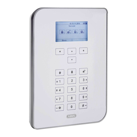
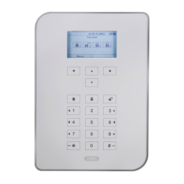
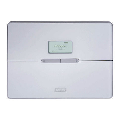
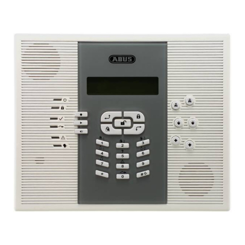
Abus SECVEST 868 User manual

1
I N S T A L L A T I O N I N S T R U C T I O N S
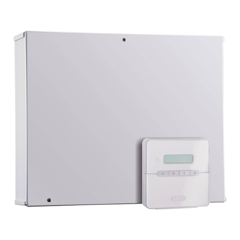
Radio alarm panel SECVEST 868
INSTALLATION INSTRUCTIONS
Perfect securit for home and office
These installation instructions are an important product
accessory. They contain important installation and operation
information. Bear this in mind if you pass the product on to
others. Store these installation instructions in a safe place for
future reference.
For a list of contents with page numbers, see page 3.
Inv.: 11772609

2
0. Introduction
Dear Customer,
Thank you for purchasing the SECVEST 868 radio alarm station. You
made the right decision in choosing this state-of-the-art technology,
which complies with the current standards of domestic and European
regulations. The CE has been proven and all related certifications are
available from the manufacturer upon request.
To maintain this status and to guarantee safe operation, it is your
obligation to observe these installation instructions.
In the event of questions, please contact your local specialist dealer.
© Security-Center GmbH & Co. KG, June 2007
Every effort has been made to ensure that the contents of this manual
are correct. However, neither the authors nor Security-Center GmbH &
Co. KG accept any liability for loss or damage caused or alleged to be
caused directly or indirectly by this manual. The contents of this manual
are subject to change without notice.
1. Usage in accordance with regulations
This radio alarm panel uses detectors and transmitters to secure your
property.
You can use it to protect your company, house, garage, garden house,
weekend cottage, etc.
The alarm panel registers unauthorised break-ins by switching output
contacts to which you can connect visual, acoustic or silent alarm
transmitters.
The alarm panel contacts and connected components must be kept
free of moisture (bathrooms and similar surroundings are to be strictly
avoided).
Use of this product for other than the described purpose may lead to
damage of the product.
Other hazards such as short-circuiting, fire, electric shock, etc., are also
possible. The power unit is designed for operation with mains electricity
at 230 Volt AC / 50 Hz.
No part of the product may be changed or modified in any way.
Connection to the public power network is subject to country-specific
regulations. Please be aware of applicable regulations in advance.

3
2. Contents
0. Introduction ................................................................................................. 2
1. Usage in accordance with regulations ..................................................... 2
2. Contents ...................................................................................................... 3
3. Precautions ................................................................................................. 5
4. Scope of delivery and accessories required ........................................... 6
5. Notes on connection and extension options........................................... 7
6. Notes on security system .......................................................................... 8
6.1 Opening the panel casing.................................................................... 8
6.2 Connections in the upper part ............................................................ 8
6.3 Connections in the base plate ............................................................ 9
6.4 Blanking off non-used cable inputs ................................................... 9
6.5 Installing the base plate....................................................................... 9
6.6 Connecting the panel to 230V mains voltage.................................. 10
6.7 Connecting wired detectors (optional) ............................................ 10
6.8 Connecting the analogue telephone (optional)............................... 11
6.9 Connecting external loudspeakers / microphones (optional) ....... 11
6.10 Adjusting the loudspeaker volume ................................................ 11
6.11 Inserting rechargeable batteries for emergency power supply .. 11
6.12 Closing the alarm panel................................................................... 12
6.13 Notes for testing the alarm panel ................................................... 12
6.14 Final steps......................................................................................... 12
6.15. Codereset ......................................................................................... 13
7. Explanation of terms ................................................................................ 13
8. Overview of alarm panel and keypad ..................................................... 16
9. Installer mode ........................................................................................... 17
10. Settings in installer mode ...................................................................... 17
10.1 First steps in installer mode............................................................ 17
10.2 List of menu items in the installer menu ....................................... 18
10.3 Configuring zones and teaching radio detectors ......................... 19
10.3.1 Defining zone name .................................................................... 20
10.3.2 Selecting zone type..................................................................... 21
10.3.3 Selecting partitions...................................................................... 22
10.3.4 Selecting zone attribute .............................................................. 22
10.3.5 Adding/deleting a detector...........................................................23
10.4 Configuring outputs .........................................................................26
10.4.1 Editing outputs.............................................................................26
10.4.2 Defining output name ..................................................................27
10.4.3 Selecting output type ...................................................................27
10.4.4. Add output ..................................................................................29
10.5 Other Devices....................................................................................31
10.5.1 External siren...............................................................................31
10.5.2 Info module ..................................................................................32
10.5.3 Wireless Accessory Module (WAM) ............................................34
10.5.4 Arming station..............................................................................36
10.6 Configuring partitions ......................................................................38
10.6.1 Configuring exit mode of partition................................................39
10.6.2 Configuring exit delay of partition ................................................40
10.6.3. Configuring entry delay of partition.............................................40
10.6.4 Activating alarm response of partition .........................................40
10.6.5. Configuring exit mode on internal activation of partition ............41
10.6.6. Configuring behaviour of zones at internal activation ................41
10.6.7. Strobe On Set.............................................................................41
10.6.8. Strobe On Unset.........................................................................41
10.7. Configuring system options ...........................................................42
10.7.1. Configuring user options.............................................................43
10.7.2. Remote Access ..........................................................................44
10.7.3. Selecting a language ..................................................................44
10.7.4. Factory settings ..........................................................................45
10.7.5. Installer code ..............................................................................45
10.7.6. Entry Timer On Unset.................................................................46
10.7.7. PA Response..............................................................................46
10.7.8. System Auto Rearm ...................................................................47
10.7.9. Siren Delay .................................................................................47
10.7.10. Siren Time ................................................................................48
10.7.11. Stray on Entry Route Delay......................................................48
10.7.12. Supervision Fail Response.......................................................49
10.7.13. Jamming Detection...................................................................50
10.7.14. Batt Load Test ..........................................................................50
10.7.15. Siren in Part Set .......................................................................51
10.7.16. Force Set ..................................................................................51
10.7.17. RF Siren Options ......................................................................52
10.8. IP Network ........................................................................................52
10.9. Configure download settings .........................................................53
10.9.1. Account Name ............................................................................54
4
10.9.2. Connection Type........................................................................ 55
10.9.3. Ring to Answer........................................................................... 55
10.9.4. Answer on 1 ring ........................................................................ 56
10.9.5. Access mode.............................................................................. 56
10.9.6. Phone Book................................................................................ 57
10.9.7. IP Network.................................................................................. 58
10.9.8. Secure Callback ......................................................................... 58
10.9.9. Modem Baud Rate ..................................................................... 59
10.10. Configuring communication settings ......................................... 59
10.10.1. Configuring alarms................................................................... 60
10.10.2. Social Care............................................................................... 72
10.10.3. Configuring speech dialler ....................................................... 77
10.10.4. SMS ......................................................................................... 81
10.10.5. Line Fail Reporting................................................................... 85
10.11. Configuring social care ................................................................ 86
10.11.1. Start/End Monitoring at ............................................................ 86
10.11.2. Monitoring Interval ................................................................... 87
10.11.3. Set Volume / Voice Connection ............................................... 87
10.12. Test function.................................................................................. 88
10.13. View Log......................................................................................... 92
10.14. Displaying system information.................................................... 92
11. ISDN/GSM/Ethernet/GPRS Module ....................................................... 93
12. USB port and programming .................................................................. 96
13. Technical data......................................................................................... 98
14. Declaration of Confirmity..................................................................... 100
15. Glossary ................................................................................................ 100
16. Installation Guideline ........................................................................... 100

5
3. Precautions
!
WARNING
!
To avoid fire and injur , please observe the
following:
•Securely fasten the device at a dry
location in the building.
•Ensure sufficient air circulation for the
alarm station.
•Do not expose the panel to
temperatures less than 0°C or more
than 50°C.
•The panel is designed for indoor use
only.
•Humidity must not exceed 90% (non-
condensed).
•Make sure that no metal objects can
be pushed into the equipment from
outside.
•Ensure that the voltage is disconnected
when carrying out work on the station.
!
IMPORTANT
!
Please observe the following regulations to
ensure trouble-free operation of our
s stem.
•The alarm panel is supplied with DC
power by means of the internal
transformer.
•The transformer is connected to the
230V AC building mains by means of
a separate, electrically protected
line.
•Connection work to the building
mains is subject to country-specific
regulations.
•A rechargeable battery supplies
emergency standby power.
•The maximum power consumption of
connected components must never
exceed 1A.
•Always replace fuses with fuses of the
same rating, never higher.
!
IMPORTANT INFO
!
Burglar alarm stations in general:
If the equipment is not correctly installed,
signals may be misinterpreted and result in
false alarms. The costs resulting from the
deployment of rescue organisations, e.g.: fire
or police, are borne by the operator of the
equipment. Therefore please read the
instructions very carefully and follow the
installation instructions for lines and
components precisely.

6
4. Scope of deliver and accessories required
Scope of deliver
Burglar alarm station
Installation Instructions
Operating instructions
Installation DVD
Downloader CD
You also need:
Alarm detector
Signal transmitter
Optionall available:
Info module
Wireless control Panel
Secvest Key
Remote Control
WAM (Wireless Accessory Module)
ISDN module
GSM module
Extras:
Tools required:
Flat screwdriver
(small)
Philips screwdriver
Drill
6mm drill bit
4mm drill bit
6mm screws
4mm screws
Wallplugs, filler, etc.

7
5. Notes on connection and extension options
The radio alarm panel is the basic device of an electronic security system for
protecting your property (e.g.: apartment, house, garage, shops, etc.). In
combination with other components such as radio detectors and signal
transmitters, it secures the areas to be monitored. The alarm is triggered by
unauthorised break-in attempts.
You can program the panel either via the integrated keypad, locally via the
software, or via the communications software and equipment. You can also
activate the panel via the integrated keypad or via remote control equipment
such as radio cylinder or radio keypad.
The radio alarm panel can transmit an alarm via analogue or digital telephone
equipment. Via the optional GSM module, the alarm can also be transmitted
via the GSM network. Alarms can be transmitted in digital form via PSTN, ISDN,
GSM, Ethernet and GPRS e.g., to a command centre, or by voice message to
selected participants such as neighbours.
The radio alarm panel has 32 radio zones and 2 wired zones that are
connected directly to the radio alarm station. The panel analyses signals from
the trained radio components according to the zone programming and can
also analyse radio communication for attempts to tamper with it.
Properties of alarm station:
•32 freely programmable radio zones, all of which can be programmed as
follows:
Immediate, entry/exit, entry to follow, 24 hour, fire, panic, key-switch, block
lock, technical or key-box.
•2 freely programmable wired alarm zones in the radio alarm panel that
can be programmed like the radio zones.
•Separately analyzed tamper and battery monitoring for every radio zone.
•4 wireless arming stations, 16 wireless telecommands, 16 pendants,
8 wireless accessory modules, 50 proximity key tags.
•2 wired relay outputs in the radio alarm panel and 32 programmable
wireless outputs that can be configured for a specific event (alarm, fire,
panic, …).
•Integrated transformer (230V AC / 12V DC) for supplying the alarm panel
and for recharging the battery.
•Emergency power supply via 6 x 1.2V NiMH rechargeable batteries
(supplied)
•Simple programming and operation via the integrated keypad or
software.
•The state of the alarm zones and the alarm panel is displayed on a plain-
text display.
•Zone blocking as a way of temporarily removing individual alarm zones
from surveillance.
•Access authorisation for operating and programming using a 4-digit code.
•
250 times alarm and event memory with date and time stamp.

8
6. Notes on securit s stem
6.1 Opening the panel casing
Install the alarm panel in the order described here.
First remove the two screws on the base of the radio alarm panel as
shown here.
Open up the top part (1) of the radio alarm panel and separate the
base plate (2) from the rest of the station. Take particular note of the
cable connections.
6.2 Connections in the upper part
The following figure shows the connections in the upper part.
Number Description
1 Internal siren
2 Battery case
3 Internal loudspeaker
4 Connection for analogue telephone
5 Kickstart and code reset jumper (KS + RESET)
6 Connector for external loudspeaker and microphone
(separate device)
7 Connector for extension modules (ISDN/GSM module)
8 Connecting cable between base plate and upper part
9 Loudspeaker volume control
10 USB port
(1)
(2)

9
6.3 Connections in the base plate
The following figure shows the connections in the panel base plate.
Number Description
1 Cable clamp for the 230V AC mains lead
2 Connector for connection cable
3 230V AC mains connection
4 Connector clamps for wired zones and outputs
6.4 Blanking off non-used cable inputs
Use the plastic blanks supplied to blank off the cable inputs that are not
used. See next figure for fitting.
6.5 Installing the base plate
Now fix the base plate to the wall as shown in the next figure. Make
sure the panel is installed so that the rear is not screened by hidden
metal. Fix the panel at a height at which the user can easily read the
information on the display.

10
6.6 Connecting the panel to 230V mains voltage
Connecting the panel to the 230V AC mains network is subject to
national regulations. Check that no voltage is present in the
connection cable when fitting. Connect the 230V mains supply to the
mains connector as shown in the diagram and do not forget to fix the
cable in the cable clamp to relieve tension on the cable:
IMPORTANT: Colour code of the mains supply
L: brown or black
Ground: green/yellow
N: blue
IMPORTANT: Always replace the mains fuse by a fuse of the same
type and never with a higher-rated fuse.
6.7 Connecting wired detectors (optional)
Connect wired components as shown in the diagram. Note that
sensors can be connected in only one way:
Zone closed when the output resistance is 2.2 kOhm (two resistors
inserted). The 4.7kOhm resistor is placed as well; however, it is by-
passed by the alarm contact of the detector (see below drawing).
In this variant, the tamper contact and alarm contact are monitored in
one zone. In the event of a change of resistance, the alarm panel can
distinguish whether it is a real alarm or tampering. Note that there are
two different resistance values:
A: 2.2 kOhm (red, red, red, gold)
B: 4.7 kOhm (yellow, violet, red, gold)

11
6.8 Connecting the analogue telephone (optional)
See Appendix B for instructions on connecting ISDN and GSM
equipment. Connect the analogue telephone as shown in the
diagram:
A-B
Connector of
external analogue
line
In UK only
A1-B1
Connector for
analogue terminal devices e.g. telephone/fax
6.9 Connecting external loudspeakers / microphones
(optional)
In addition to the internal loudspeaker and microphone, you can also
connect a further loudspeaker / microphone to the radio alarm panel
as shown in the diagram. For this, order the FU extension set.
6.10 Adjusting the loudspeaker volume
You can adjust the volume of the internal (external) loudspeaker with
the volume control shown. This affects only non-alarm signal tones. The
volume of alarm tones cannot be adjusted. Adjust the volume as
shown here:
Quieter
Louder
6.11 Inserting rechargeable batteries for emergenc power
suppl
Place the batteries (note parity) in the battery case. Replace the
batteries every two years at the latest by batteries of the same type.
Use batteries with the following specifications only:
1.2 – 1.5VDC, 2100mAH, NiMH

12
6.12 Closing the alarm panel
Reconnect the upper part to the base plate. Do not forget to fit the
connection cable between the base plate and the alarm station. At
the same time, check that all other connections (emergency power
supply and loudspeaker) are correctly connected to the upper part.
Now close the panel and replace the casing screws on the base.
Do not connect to 230V AC until the panel is properly reassembled.
6.13 Notes for testing the alarm panel
To test the alarm panel functions without fixing the panel to the wall
and without 230V AC mains voltage, you have to activate the system
via the kickstart.
After inserting charged batteries, short-circuit the kickstart jumper on
the upper side of the alarm panel to put the radio alarm panel into
operation.
6.14 Final steps
You have now made all connections and the radio alarm panel is
ready for programming.
Note: When you connect the radio alarm panel to the power supply for the first
time, the radio alarm panel asks you to select the language to be used by the
display, followed by the default programming options for a particular country.
You can examine the defaults when you enter programming mode.
Irrespective of whether you have connected the panel to 230V AC
mains voltage or short-circuited the kickstart jumper, the panel is now in
user mode.
Before you start programming, read the explanation of terms in the
following section. If you are familiar with these terms, you can skip the
next section and start programming the station.

13
6.15. Codereset
If the installer and/or administrator code gets lost, it is possible to
execute a code reset. In this way all user settings (also programmed
telecommands) will be deleted and the factory defaults for installer
and user codes are reset. All programmed settings in the installer menu
will remain and will not be deleted or reset.
The factory default for the installer code is 7890
The factory default for the administrator code is 1234
7. Explanation of terms
Before starting to program the alarm station, you should understand
the terms used. An explanation of zone types and their attributes.
NOT USED
Program a zone for which no radio detector has been trained or to
whose input no detector has been wired and is therefore no noted as a
Not Used zone type.
NORMAL ALARM
If the alarm panel is active, this zone immediately triggers an alarm if a
radio detector sends a change to the radio alarm panel or if the state
of the alarm zone changes (e.g., opening the alarm contact).
ENTRY ROUTE
This zone triggers no alarm if an entry/exit zone has previously activated
the entry delay time. An immediate alarm is triggered if no entry delay
is first activated. You can use this zone type for a motion sensor in the
entrance hall pointing to the entry door (fitted with a door contact).
This detector can be used as an entry/exit detector for internal
activation. This zone can be opened when you exit the installer menu.
FINAL EXIT
If the burglar alarm panel is active, this zone first triggers an alarm
following a specified delay time (entry delay). This zone type can be
used for the door contact of your entrance. When you leave the
premises, closing this zone can also be used for ending the exit delay.
24 HOUR
This zone always triggers an immediate alarm. If the alarm panel is
deactivated, the alarm is first heard via the integrated buzzer in the
station. In an active state, the siren output is also activated. If a 24-hour
zone is locked, this applies to the deactivated state only.
1. Remove power from the panel
(Mains and battery power supply
needs to be removed)
2. Short cut he code reset jumper
3. Reapply mains to the panel
4. Open the code reset jumper

14
FIRE
This zone always triggers an alarm, irrespective of whether the burglar
alarm panel is activated or deactivated. The alarm tone is affected via
the buzzer in the radio alarm panel and the external siren as a pulsed
alarm tone. Teach only fire detectors for this zone.
PA (PANIC)
This zone always triggers an alarm, irrespective of whether the burglar
alarm panel is activated or deactivated. A panic alarm can also be
transmitted silently (e.g.: via an optional telephone dialler). The
program menu can be exited only when this zone is closed.
TECHNICAL ALARM
In deactivated state, a technical zone triggers an alarm via the radio
alarm panel and an optional dialler. In activated state, no alarm is
triggered. If an alarm occurs in this zone in activated state, this is
displayed when the alarm panel is deactivated. You can use this zone
type for flood sensors.
KEY SWITCH MOMENTARY
Train a key-switch (pulse) for the radio alarm station. Any change to this
zone changes the state of the alarm panel from active to inactive or
from inactive to active (following a timeout of the delay time).
KEY SWÌTCH LATCHED
A key switch (permanent) can be connected to the burglar alarm
station. Any change to this zone changes the state of the alarm panel
from active to inactive or from inactive to active (following a timeout
of the delay time). Note that you can operate the alarm panel only via
the key switch. If the state is unclear, e.g.: the key switch is closed, and
deactivated at the radio alarm panel, the alarm panel can return to
active state.
Notes:
1. These two zone types are intended for use on zones that connect
to an access control keypad, electronic key or other type of
hardwired device used to set or unset the system.
2. When the user operates the keyswitch while the system is unset
then the radio alarm panel starts the programmed e it mode.
3. When the user operates the keyswitch while the system is set
then the radio alarm panel unsets the system immediately.
4. The user cannot reset the system from a Keyswitch zone.
5. Do not assign more than one Latched Key Switch zone to one
partition.
KEY BOX
This zone is mainly used in Scandinavia. If this zone is opened, this event
is stored in the memory of the burglar alarm station. The event can also
be transmitted via the telephone dialler. No alarm is triggered. When a
zone of this type is required, the Installer connects the alarm wires of
the zone (usually the auxiliary contacts of a door contact) to a special
external key box and the tamper wires to the box enclosure switch.
When someone opens the box the radio alarm panel logs the event
and communicates it to the ARC.
Exit Normal Alarm
A zone programmed as ‘Exit Normal Alarm’ behaves similarly to a
Normal Alarm zone. However, a zone of this type will start an alarm if
the detector is triggered during the exit time.
ZONE
A zone is a detector that has been trained for the radio alarm station.
Zones can have very different attributes. The detector does not know if
the radio alarm panel is active or not. A detector therefore always
sends an alarm to the panel if it registers a change. The radio alarm
panel then evaluates whether this message is to trigger an alarm
response or not.

15
SYSTEM SET
When the radio alarm panel is active, it monitors all zones for changes
to the line voltage and triggers a local alarm and optionally an external
alarm.
SYSTEM UNSET
When the radio alarm panel is inactive, it monitors only zones that are
always active, such as 24-hour zones, technical zones, and fire alarms.
An alarm triggered by one of these zones usually results in an internal
alarm.
SYSTEM PART / COMPLETE SET
In addition to the complete activation of the burglar alarm station, you
can also activate individual partitions (A, B, C, D). In addition you can
also internally set your alarm system. This means that areas can be
activated and protected even if you are at home. To use the function
s stem / partition part set ou need to programme at least one
detector with the zone attribute “part set” (see detectors
configuration).
INTERNAL ALARM
In the case of an internal alarm, only the buzzers of the radio alarm
panels and the optional loudspeakers are activated.
LOCAL ALARM
In the case of a local alarm, the connected combination signalling
devices (flashlight and siren) are also activated.
EXTERNAL ALARM
In the case of an external alarm, not only the acoustic and visual
signalling devices are activated: the alarm is also transmitted via
telephone.
PARTITIONS
The radio alarm system has a total of 4 partitions. Each of these
partitions can be activated or deactivated individually. Each detector
can be assigned to one or more partitions. The detector is not
monitored until all partitions to which the detector is assigned have
been activated (exception: detectors that are always active such as
fire or 24-hour detectors).
COMMUNICATION
Using the menu option communication in the installer menu you can
setup four different possibilities to transmit an external alarm.
Alarms
This type of alarm transmission is used if the alarm panel is connected to
a monitoring station. The transmission is done via digital protocol. This
type of transmission can not be used to transmit an alarm to a public
telephone. You can either use the SIA or Contact ID protocol, as well as
Fast Format.
Social Care
This type of alarm transmission is similar to the alarm transmission and
also transmits only a digital protocol. In this case the panel offers other
digital protocols. This type of transmission cannot be used to transmit an
alarm to a public telephone.
Speech dialler
This type of transmission is used to transmit an alarm to a public
telephone. In this case the alarm panel works similar to an answering
machine. Pre recorded messages are being transmitted to predefined
phone numbers. The called person hears the recorded message and
can acknowledge the alarm if necessary.
SMS
The transmission type SMS is done similar to the transmission via speech
message. Pre set SMS messages will be send to predefined phone
numbers. SMS messages can also be transmitted via the analogue
telephone line (service availability is depending on the phone system).

16
8. Overview of alarm panel and ke pad
Read area of chip key
Graphic display
Multiline display
Button for activating
radio alarm station
Keypad for
programming and
operating the station
Keypad cover
Integrated siren and
loudspeaker
Button for
deactivating radio
alarm station
Control buttons
Keypad alarm keys
for panic, fire,
medical and social
care alarm
Integrated
microphone

17
9. Installer mode
There are two ways of programming the radio alarm station:
A: Via the keypad on the radio alarm station.
B: Via the software either locally or via the communications software.
The following describes how to program the radio alarm panel via the
keypad. To program the radio alarm panel via software, see the
software instructions.
The installer menu is graphically designed to be used almost intuitively.
You move within the installer menu by pressing the control buttons.
With the arrow keys, you navigate up and down within a menu item
according to the direction of the arrow. The buttons on the left and
right refer to the LCD display and have various functions.
10. Settings in installer mode
10.1 First steps in installer mode
In user mode, do the following:
Enter a valid installer code:
7 8 9 0
(Factory setting of installer code: 7890)
After entering the installer code, you have to enter an administrator
code. When delivered, the administrator code is 1234:
1 2 3 4
The radio alarm panel changes to installer mode and displays the
following text: “You are in installer mode”.
With the control buttons you can now scroll through the menu
items in installer mode. For a list of the menu items, see the next page
(Table 1).
To select a menu item, press the control button under the word
Select.
To exit a menu item, press the control button under the word
Back.
To exit installer mode, press the control button under the word
Exit.

18
Confirm the display Leave Installer mode by pressing the control button
under the word Yes.
The radio alarm panel changes to user mode and displays the
following text:
“You have left installer mode.”
10.2 List of menu items in the installer menu
In installer mode, you can teach radio detectors, configure
controllable outputs, define partitions, etc. The following table provides
a summary of the menu items:
Menu item Settings
Detectors Teach/delete detector, configure zones
Outputs Add outputs/edit outputs
Other Devices Install external sirens, WAM (Wireless Accessory
Module), info module, remote radio alarm panel
Partitions Assign partitions to zone, configure partitions
System Options Perform user functions, select language, restore
default settings, change installer code, define
delay and siren times, configure supervision and
radio jamming detection
IP Network Configure IP settings
Download Configure download settings
Reporting Configure telephone settings, define transmission
types
Social Care Configure social care, define time window
Test Panel and detector test, output test, walk test,
radio communication
View log Read event log
About Read information about software and hardware
state
Table 1: Menu items in the installer menu

19
10.3 Configuring zones and teaching radio detectors
If you are in user mode, you first have to change to installer mode.
Proceed as follows:
Enter a valid installer code (factory setting 7890):
7 8 9 0
You may also have to enter the master code (factory setting 1234).
The radio alarm panel changes to installer mode and displays the
following text:
“You are now in installer mode”.
You see the following graphic display:
Select this menu item by pressing the control button under the
word Select.
You see the following graphic display:
Press the control button to select Edit Zones and confirm by
pressing the control button under the word Select. To cancel
input, press the control button under the word Back.
After confirming Edit Zones with the Select button, you receive the
following graphic display:
This shows you a summary of the configuration of the displayed zone.
An explanation of the menu items:
Displa Meaning
Name Zone name (freely definable for greater clarity, e.g.:
BW Bathroom, RM Kitchen, MK Entrance).
Type Zone type (e.g.: final exit, fire, panic, etc.).
Partitions This zone is monitored if at least one of the displayed
partitions is active.
Attributes You cannot select this item. The display shows the
zone attribute:
C: Door chime function active
S: Detector soak test active
A: Activity control active
P: Zone in part set monitored
F: Force Set Omit, this means that the zone is
automatically
omitted if it should still be open when arming the
panel.
Table 2: Menu items in “Detectors” menu

20
To see the attributes of another zone, use the control buttons to
switch between zones.
To edit the selected zone, select Edit by pressing the control button
under the word Edit. To cancel input, press the control button
under the word Back.
If you confirm Edit with the Edit button, you see the following graphic
display:
For the meaning of the menu items, see Table 2 on the left.
Use the control keys to select a menu option. Confirm your
selection by pressing the control button under the word Select. To
cancel input, press the control button under the word Back.
NOTE:
Wireless remote controls and pendants are not learned into the panel
in this menu but are added to the user. Please learn remote controls
and pendants in the user menu. Both detectors do not use up radio
zones.
10.3.1 Defining zone name
If you confirm Name with the Select button, you see the following
graphic display:
The cursor flashes at the last character. Use the control key to
move the cursor to the left or the right. To delete a letter, press the
control button under the word Delete. To save your input, press
the control button under the word OK.
Enter letters via the keypad. Letter-to-key assignment:
Table of contents
Other Abus Security System manuals

Abus
Abus TVAC14000A User manual

Abus
Abus Terxon SX AZ4000 User manual

Abus
Abus SECVEST FUAA50000 User manual

Abus
Abus PPIC35520 User manual

Abus
Abus CASA10010 User manual

Abus
Abus PLHA10000 User manual

Abus
Abus CITADEL Alarm Set Micral Manual

Abus
Abus FUBE30000 User manual

Abus
Abus AirSecure CO2WM110 User manual

Abus
Abus FUBE35001A User manual

Abus
Abus Alarmbox 2.0 User manual

Abus
Abus EYSEO TV7160 User manual

Abus
Abus Outdoor motion detector PIR User manual

Abus
Abus PPIC90010 User manual

Abus
Abus TVAC71070 User manual

Abus
Abus Secoris ESEZ60500 User manual

Abus
Abus TVAC16000B User manual

Abus
Abus TVVR30004 User manual

Abus
Abus TVAC16000B User manual

Abus
Abus Secvest FU8006 User manual