Armstrong AM-91A Owner's manual

Bulletin 549-A
This bulletin should be used by experienced personnel as a guide to the installation and maintenance of AM-91A,
-92A, 93A; AMAF-91A, -92A, -93A; AMEF-91A, -92A, -93A; FSA-91A, -92A, -93A; VSA-91A, -92A, -93A direct area humidifiers. Se-
lection or installation of equipment should always be accompanied by competent technical assistance. We encourage you to contact
Armstrong or its local representative if further information is required.
Installation and Operation
AM-91A, -92A, 93A; AMAF-91A, -92A, -93A; AMEF-91A, -92A, -93A;
FSA-91A, -92A, -93A; VSA-91A, -92A, -93A
Humidifiers for Direct Area Humidification
Step 1. Check Shipment Against Packing List
All components are listed on the packing
slip. Report any shortages immediately. If
the humidifier or accessories have been
damaged in transit, notify us and file claim
with the transportation company.
Step 2. Mount the Humidifier
Support it from the ceiling, Fig. 1-3, or bracket
it to a column as shown in Fig. 1-4. There are
holes on both sides of the humidifier for mounting
purposes.
Exception: Where supply and return connections
for the 91 & 92 size are short, a pipe hanger to
the steam supply line should be sufficient.
Figure 1-3. Figure 1-4.
Humidifier suspended from ceiling. Humidifier bracketed to column.
*Standard spring — furnished when no spring range is specified.
AM, VSA Models AMEF, AMAF,
FSA Models
Figure 1-1. Figure 1-2.
Dimensions, Armstrong Area Humidifiers. Fig. 1-1 VSA, AM models do not
have fans. Fig. 1-2 FSA, AMEF models have electrically operated fans. AMAF
models utilize air powered fans.
Installation Procedure
B
C
DF
J
E
H
G
C
DF
B
J
E
Table 1-1
Model No. B C D E F G H J
AM-91A 15-15/16” 3-3/8” 3-13/16” 6-1/16” 3-1/16” — — 13-1/4”
AMAF-91A 15-15/16” 3-3/8” 3-13/16” 6-1/16” 3-1/16” 15-5/8” 14-9/16” 13-1/4”
AMEF-91A 15-15/16” 3-3/8” 3-13/16” 6-1/16” 3-1/16” 18-9/16” 15-3/4” 13-1/4”
FSA-91A 10-7/8” 3-3/8” 3-13/16” 6-1/16” 3-1/16” 17-3/8” 15-3/4” 13-1/4”
VSA-91A 10-7/8” 3-3/8” 3-13/16” 6-1/16” 3-1/16” — — 13-1/4”
AM-92A 15-15/16” 3-3/8” 3-13/16” 6-1/16” 3-13/16” — — 13-1/4”
AMAF-92A 15-15/16” 3-3/8” 3-13/16” 6-1/16” 3-13/16” 15-5/8” 14-9/16” 13-1/4”
AMEF-92A 15-15/16” 3-3/8” 3-13/16” 6-1/16” 3-13/16” 18-9/16” 15-3/4” 13-1/4”
FSA-92A 10-7/8” 3-3/8” 3-13/16” 6-1/16” 3-13/16” 17-3/8” 15-3/4” 13-1/4”
VSA-92A 10-7/8” 3-3/8” 3-13/16” 6-1/16” 3-13/16” — — 13-1/4”
AM-93A 25-1/2” 4-5/8” 4-3/4” 9” 4-3/4” — — 24”
AMAF-93A 25-1/2” 4-5/8” 4-3/4” 9” 4-3/4” — 17-3/4” 24”
AMEF-93A 25-1/2” 4-5/8” 4-3/4” 9” 4-3/4” 21” 18-1/4” 24”
FSA-93A 20-3/8” 4-5/8” 4-3/4” 9” 4-3/4” 21” 18-1/4” 24”
VSA-93A 20-3/8” 4-5/8” 4-3/4” 9” 4-3/4” — — 24”
Table 1-2
Note: AM models 91, 92 and 93 shown on this bulletin are furnished with
Armstrong C-1801 pneumatic operators. Operator Spring Ranges for
pneumatically controlled humidifiers.
Armstrong C-1801
Operating Range Adjustable Start Points
5 lbs. 3 psig min. - 6 psig max.
*10 lbs. 3 psig min. - 6 psig max.

2
Step 3. Run the steam supply line from the steam
header to the humidifier as indicated in Fig. 2-1. Observe
the following:
A. Take steam supply line from the top of the supply
main – never from the side or bottom. If several
humidifiers take steam from a single supply line,
be sure to trap the end of the run-out with an Arm-
strong Trap of suitable size. If the steam supply is
very wet, install a drip pocket or separator ahead
of the humidifier.
B. Size supply line in accordance with Table 2-1. If
the steam supply is 5 psi or less, it is advisable to
use one pipe size larger and reduce the pipe size
just ahead of the strainer and humidifier.
C. Pitch the supply line in the direction of flow.
Humidifier Piping
D. Expansion and Contraction. With average length
of supply line, the dimension change from hot to
cold should not exceed 2”. Provide piping with 3
elbows to get swing to take care of expansion and
contraction (See Fig. 2-2).
E. Clean piping. After running the supply line, blow
down at full steam pressure to eliminate dirt and
pipe cuttings.
F. A Pipe Strainer is furnished with each humidifier.
Install (after blowing down supply line) as indi-
cated on drawing.
G. Swivel connections may be desirable – see
Fig. 2-2 and explanatory captions.
H. Pressure Reducing Valve. If required refer to
Fig. 3-1 and explanatory captions.
Table 2-1 Recommended Pipe Sizes
Humidifier
Size
Supply Header
to Strainer
Steam Inlet
& Strainer
Drip
Leg
Trap
Piping
91 3/4” 3/4” 1” 3/4”
92 3/4” 3/4” 1” 3/4”
93 1-1/4” 1-1/4” 1-1/4” 3/4”
Steam Pipe Capacities
For computing ability of piping to deliver an adequate supply of steam to
humidifier. Capacities shown are in pounds per hour.
Table 2-2 Steam Pipe Capacity at 5 psi
Pipe
Size in.
Pressure drop, psi per 100 ft. of pipe length
1/8 1/4 1/2 3/4 1
12431 44 54 62
1-1/4 52 68 97 120 140
1-1/2 81 100 150 180 210
2 160 210 300 370 430
2-1/2 270 350 500 610 710
Table 2-3 Steam Pipe Capacity at 15 psi
Pipe
Size in.
Pressure drop, psi per 100 ft. of pipe length
1/8 1/4 1/2 3/4 1 2
1 27 38 53 65 76 110
1-1/4 59 83 120 140 160 230
1-1/2 91 130 180 220 260 360
2 180 260 370 450 520 740
2-1/2 300 430 600 740 860 1210
Table 2-4 Steam Pipe Capacity at 25 psi
Pipe
Size in.
Pressure drop, psi per 100 ft. of pipe length
1/8 1/4 1/2 3/4 1 2
3/4 15 21 30 37 43 60
1 30 43 61 75 86 122
1-1/4 67 95 130 160 190 260
1-1/2 100 140 210 250 290 410
2 210 300 420 510 590 840
2-1/2 340 490 690 850 980 1380
Table 2-5 Steam Pipe Capacity at 50 psi
Pipe
Size in.
Pressure drop, psi per 100 ft. of pipe length
1/4 1/2 3/4 1 2 5
3/4 27 38 47 54 76 120
1 54 77 94 110 150 240
1-1/4 120 170 210 240 340 530
1-1/2 180 260 320 370 520 830
2 370 530 650 750 1060 1680
2-1/2 620 870 1070 1240 1750 2760
Figure 2-1.
Figure 2-2.
Strainer
Steam
Trap
Dirt
Pocket Check
Valve
Take off top o
f
steam supply
To low
pressure return
Pitch down 1/2" in 10'
Typically pneumatically controlled humidifier installation.
Strainer
Steam
Trap
Dirt
Pocket
Check
Valve
To low
pressure return
Take off top of
steam supply
Pitch down
1/2" in 10'
Swivel connections shown above permit direction of discharge
to be altered easily. Loosen both unions, adjust direction, then
retighten unions.

3
Step 4. Install the Armstrong Steam Trap and connect
the trap to the return header. It is important:
A. To provide a dirt pocket ahead of the trap as
shown in the drawings.
B. To make sure the return header pressure is well
below the steam supply pressure. Never connect
a humidifier trap to a line carrying returns from
high pressure traps.
Step 5. Install Fan and Motor of AMAF, AMEF, and FSA
units. The bracket is located on the side opposite the
steam discharge outlet in the humidifier cap. Cap screws
are provided.
Step 6. Make Electric Connections for AMEF model fan
motors. Electrical connections are shown in double dash
lines in Fig. 3-2.
A. If automatic control of the fan motor is desired, in-
stall a pneumatic-electric relay. The relay should
be set to start fan with a 2 psi air signal.
See Fig. 3-2.
P.R.V. Installation. Reducing Valves. Where the steam
pressure available for humidifiers is too high, a reducing
valve of the single-seated or dead-end type should be
used. The reducing valve should be at least 10 ft. from the
humidifier. If the supply line is more than 20 ft. long, pro-
vide a drip pocket and extra trap just ahead of the pressure
reducing valve.
Relief Valve. A pressure relief valve between the humidifier
and pressure reducing valve is a good insurance. Humidi-
fier bodies are only rated for 60 psig steam service.
Pressure Gage. A pressure gage or connection for install-
ing a gage between reducing valve and the humidifier may
save its cost many times over.
Air and Electrical Connections
10' Min. Strainer
Steam
Trap Steam
Trap
Steam
Supply
Dirt
Pocket
PRV
Relief
Valve
Pressure Gage
To Low
Pressure
Return
Check
Valve
Figure 3-1.
Motor
Compressed air hookup. Electrical connections for AMEF units are shown. For AMAF model omit electric.
Compressed air hookup showing air powered fan and air line accessories for AMAF units.
Wiring diagram for standard 120V or
240V FSA or VSA Humidifiers.
Wiring diagram for 120V or 240V VSA
Humidifier with 24V line to humidistat.
Steam In
Steam Trap
Steam
Trap
Pneumatic
Temperature
Switch
Pneumatic
Temperature Switch
Air Supply
Oiler
Air Fan Assembly
Steam In
Humidity
Controller
Filter
Steam
Out
120 V 240 V Line In
P.E. Switch
Humidity
Controller
Hand
Switch
Armstrong A-8581-A
(HC-101) Humidity
Controller
Armstrong A-8581-A
(HC-101) Humidity
Controller 24 V
Power Source
Power Source
Solenoid Coil
Solenoid Coil
Temp. Switch
Temp. Switch
Switch
Fan
(when used)
Junction
Box
Junction
Box
Relay
Air
In
Switch
Fan
(when used)
Figure 3-4.
Figure 3-3. Figure 3-5.
Figure 3-2.

4
B. If automatic control is not used, the use of a hand
switch to control the fan motor has definite ad-
vantages. The fan operates continuously during
the heating season. The motors are oil less in all
positions. Current consumption is low – 6 watts
for all AMEF models.
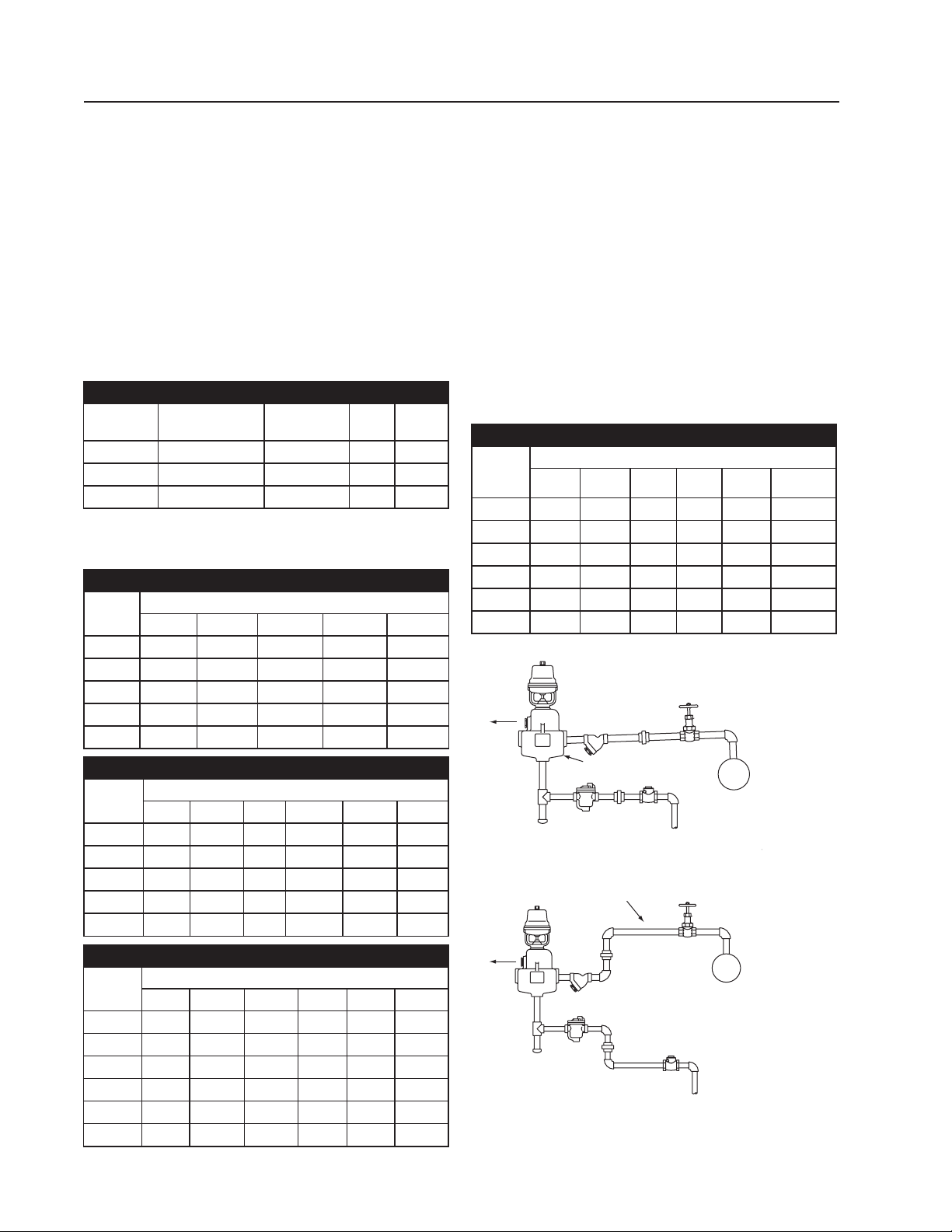
For FSA, VSA Models (See Figs. 3-4 & 3-5)
A. Beware of Voltage Drop. If the wire supplying
current to the humidifier is too small or too long,
there may be a voltage drop that will reduce the
life of your equipment. When the voltage is too
low, the solenoid valve will not open but current
will continue to flow and will burn up the coil.
B. 24 Volt Wiring. (VSA Only) Where codes permit
24 volt wiring without conduit, the use of a 120-24
volt transformer relay, as shown in Fig. 3-5 will
lower the installation cost.
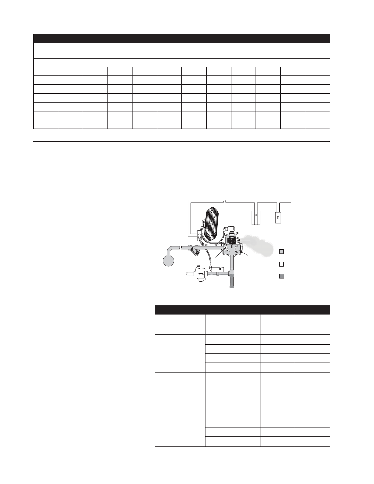
Step 7: Install Pneumatic Piping. (AM)
A. Air Supply. Air supply for Armstrong Humidifiers
should be 15 to 20 psi. This air must be clean and
dry instrument air. Make air connections to fan of
AMAF models.
B. Compressed Air Piping. Plastic tubing or equiva-
lent is used for all air connections.
Step 8: Install Humidity Controller.
Location. The humidistat should be installed anywhere
from 20 ft. to 30 ft. from the humidifier – at one side of
the air stream from the humidifier. The hygrostat should
be able to “see” the unit controlled. It must not be hidden
behind piles of goods or in channels of columns where air
movements cannot reach it. It may be necessary to experi-
ment with the location in order to get the best control.
Setting and Adjusting should be done in accordance with
the manufacturer’s instructions furnished with the humidi-
stat.
Recommended Option.
A pneumatic or an electric temperature switch is recom-
mended in any system where the steam supply to the
manifold jacket and humidifier body may be interrupted or
turned off.
Air and Electrical Connections
Sizing and Selection
A survey of your requirements should be taken to deter-
mine the amount of steam needed for humidification, the
number, size and type of units required, and the location of
both humidifier and humidity controllers.
Sizing and location with natural ventilation.
These are the average industrial humidification applications
with:
Room temperatures – 65° to 80°.
Relative humidities – 35% to 80%.
Natural ventilation – i.e., infiltration around windows and
doors.
Selection Data Required.
■Minimum Outdoor Temperature: for most jobs, figure
10°F above the lowest recorded temperature for your
locality. The lowest temperatures are seldom
encountered for more than a few hours.
■Indoor Temperature
■RH Desired
■Pressure of Steam Available for Humidification
■Number of Cubic Feet in Room
■Air Changes Per Hour: air changes taking place under
average conditions exclusive of air provided for
ventilation or regain of hygroscopic materials.
Rooms, 1 side exposed................... 1
Rooms, 2 sides exposed ................. 1 ½
Room, 3 or 4 sides exposed............ 2
Rooms with no windows or
outside doors............................ ½ - ¾
Typical Problem:
Design outdoor temperature............ 0°F
Indoor temperature.......................... 70°F
RH required ..................................... 40%
Air changes per hour ....................... 2
Steam pressure available................ 5 psi
Room size 400’ x 160’ with 10’ ceiling.
Natural ventilation
Heated by:
Unit heaters – fan on-off control.
Step 1: Steam required for humidification. Our room con-
tains (400’ x 160’ x 10’) or 640,000 cu. Ft.
From the 70°F Table 5-1, read across from 0°F outside
temperature to the 40% RH column where you find the
figure .409 lbs. of steam per hour per 1000 cu. ft. of space
for each air change. Then, 640 x .409 x 2 equals 524 lbs. of
steam per hour installed humidification capacity required.
Step 2: Electric or air controlled units. The large floor area
calls for multiple humidifiers. No explosion hazard has
been specified so use of air controlled units is not required.
Electric units are recommended.
Step 3: Number of humidifiers for job. Divide steam
required by capacity of humidifiers at steam pressure avail-
able.
Step 4: What size humidifier to use. For this example, a
large number of smaller capacity units is recommended.
Larger capacity units could cause condensation on the low
ceiling. Also, because of the large floor area, the humidi-
stats for fewer units would be widely spaced, which could
result in less accurate control than desirable.

5
Step 5: What type of humidifier to use. In this example, in-
tegral fan units are preferable to steam jet units installed in
conjunction with unit heaters. Since the unit heater fans are
on or off to control temperature, it follows that the humidi-
stat may call for steam when the nearest unit heater is nor
running. With the low ceiling, the discharge from a steam
jet humidifier might rise to the ceiling and produce conden-
sation. Therefore, the integral fan type should be used.
Step 6: Location of humidifiers. Several patterns are pos-
sible, and actual location can usually conform with the ex-
isting steam supply and return lines to make an economical
installation with a minimum of new piping.
In our problem of a 400’ x 160’ x 10’ room, there would
likely be steam lines along both sides of the room, and
humidifiers can be located as shown in Fig. 5-1. If the sup-
ply lines run down the center of the room, the center line
pattern would be practical. Runouts to integral fan units
in a 160’ wide room would be about 20’ long. If the room
were only 60 or 80 ft. wide, runouts need be no longer than
required for actual hook-up.
Step 7: Location of humidistat. This should be form 20 to
30 feet away from the humidifier and slightly to one side of
the air stream from the unit. The humidistat should “see” its
humidifier. Do not hide it behind a post or in the channel of
an H-beam. It must get a good sample of the air, to control
the humidity.
Sizing and location with forced ventilation.
Typical jobs: Mill and sanding rooms in furniture factories.
Here, the problem of selecting and installing humidifiers is
much the same as previously described except for:
A. Determining the number of air changes.
B. Location of humidifiers and humidistat.
Air Changes: These can be determined from exhaust fan
capacity where known. The cu. ft. per hour capacity of the
fans divided by the cubic feet of space to be humidified will
give the number of air changes.
Where the capacity of fan or fans is not known, air changes
can be measured with velometer readings at all open
doors, elevator shafts, etc., leading to the room and with
fans operating at full capacity. Your Armstrong Representa-
tive can determine air changes for you.
Humidifier Location: Bear in mind that humidifiers will
have to control the humidity 24 hours a day, seven days a
week during the heating season. Exhaust fans may operate
only 40 hours or 80 hours per week. Thus the humidifiers
and humidistats must be located for good distribution of
humidity during the fan-off periods as well as when the fans
are operating. Figure 5-2 outlines a typical requirement.
Sizing and Selection
Figure 5-1. Figure 5-2.
Where practical, locate humidifiers to minimize
piping. Locations shown where steam supply
lines are along outer walls; and where supply
is in center of room.
Schematic layout of humidifiers in woodworking plant
where exhaust fans are used. Arrows indicate air flow
induced by fans. Humidifiers are sized for load conditions
imposed by fan. Humidifiers are located to give uniform
distribution of humidity when fans are off or when fans
are running.
Table 5-1
70°F. Humidification. Pounds of Steam Per Hour, Per Air Chcange for Each 1000 cu. FT. of Space to Secure Desired Indoor Relative
Humidity at 70°F. with Various Outdoor Temperature (Outside Air 75% Saturated).
Outdoor
Temp.
70°F. - RELATIVE HUMIDITY DESIRED INDOORS-70°F
25% 30% 35% 40% 45% 50% 55% 60% 65% 70% 75%
30 .079 .136 .194 .251 .309 .367 .424 .482 .539 .597 .654
20 .154 .212 .269 .327 .385 .441 .499 .557 .615 .672 .730
10 .204 .262 .319 .377 .434 .492 .549 .607 .665 .722 .780
0 .237 .294 .352 .409 .467 .524 .582 .639 .697 .754 .812
-10 .257 .314 .372 .430 .487 .545 .602 .660 .717 .775 .832
-20 .270 .327 .385 .442 .500 .557 .615 .672 .730 .787 .844

6
How electrically operated units work.
After passing through the Armstrong inline
strainer, steam enters the cast iron steam-
separating chamber. The use of cast iron
as a separator is probably the single most
important feature in the Armstrong humidi-
fier design.
The preferred material of strength and
durability, case iron gives Series 9000
humidifiers flexibility in design without
fabrication. In addition, castings mean
better heat retention because of thicker
walls. Which in turn means a lower rate of
condensation.
Entering the main separating chamber,
steam encounters a cupped baffle which
reverses its flow and turns it back on itself.
The outer walls of the casting form another
cup, and the same thing happens again.
These two 180° turns help condition the
steam, reducing its volume and separating
the condensate from the vapor. Conden-
sate from supply and radiation and most of
the particulates in the steam not removed
by the strainer collect in the large drain leg
and are discharged through the inverted
bucket drain trap.
Steam from the separating chamber flows
around and through the solenoid valve
which is actuated by a demand signal from
the humidistat. (Solenoid can be ex-
changed for electric or pneumatic control
if desired by choosing an operator and
bonnet assembly).
Next the steam flows into the drying cham-
ber which is jacketed by the separating
chamber. The drying chamber is filled with
a stainless steel silencing material which
almost completely absorbs the noise of
escaping steam. Dispersion is through a
jet nozzle or by a fan.
How air-operated units work.
Air-operated units operate in the same
manner as electric units except that they
Operation
Figure 6-1.
utilize a pneumatic humidistat as humidity controller in the space and an
air operator to open and close the steam valve.
Explosion hazard humidification.
Sizing air-operated humidifiers for areas where an explosion hazard ex-
ists is done exactly as for other requirements except that they should be
sized for the most severe conditions of makeup air, RH required and
minimum steam pressure.
Table 6-1
75°F. Humidification. Pounds of Steam Required Per Hour, Per Air Chcange for Each 1000 cu. FT. of Space to Secure Desired Indoor Relative
Humidity at 75°F. with Various Outdoor Temperature (Outside Air 75% Saturated).
Outdoor
Temp.
70°F. - RELATIVE HUMIDITY DESIRED INDOORS-70°F
25% 30% 35% 40% 45% 50% 55% 60% 65% 70% 75%
30 .129 .196 .264 .331 .399 .466 .533 .601 .668 .736 .803
20 .204 .271 .339 .406 .474 .541 .609 .676 .744 .811 .879
10 .254 .321 .389 .456 .524 .591 .659 .726 .794 .861 .929
0 .286 .354 .421 .489 .556 .624 .691 .759 .826 .894 .961
-10 .307 .374 .442 .509 .577 .644 .711 .779 .846 .914 .981
-20 .319 .387 .454 .522 .589 .657 .724 .792 .859 .927 .994
Strainer
Fan
Solenoid Valve Open
Humidistat
Switch
Separating
Chamber
Drying
Chamber
Temperature
Switch
Baffle
Steam
Trap
Steam
Supply Condensate
Steam at
Atmospheric Pressure
Steam at
Supply Pressure
Table 6-2 Location of Unit Humidifiers for Direct Discharge into Atmosphere.
Method of Steam
Dispersion
Maximum Discharge
Capacities in lbs. of
Steam per hour
Minimum
Ceiling
Ceiling
Clearance
30 8’ 2’
Electric Fan 80 10’ 3’
FSA, AMEF Models 200 14’ 6’
300 16’ 8’
30 10’ 3’
Air Fan 80 12’ 4’
AMAF Models 200 16’ 8’
300 20’ 8’
30 10’ 4’
Jet 80 12’ 6’
VSA, AM Models 200 20’ 10’
300 20’ 10’

7
Putting the Humidifier Into Operation
When Temperature Switch is Employed simply set hu-
midity controller at desired level, and turn on the steam.
When Temperature Switch Is Not Employed deactivate
operator control so that humidifier control valve will remain
closed. Then:
A. Open steam supply valve, to bring humidifier up
to temperature.
B. When drain line from humidifier is at steam
temperature, activate the operator control.
C. Set desired relative humidity.
After the Humidifier Is In Operation
Clean Strainer. The screen in the strainer installed in the
steam supply line should be cleaned a few days after the
humidifier is placed in operation, and thereafter at least
once each season – more often if you find much dirt in the
screen.
Check Trap. The steam trap is used to drain the humidi-
fier should be inspected at the same time the strainer is
cleaned.
Trouble Shooting FSA, VSA
Humidifier Will Not Discharge Steam
A. –Solenoid Fails to Open
1. Burned out coil.
2. Humidistat at fault.
3. Hand switch open.
4. Dirt in plunger tube or bent tube.
5. Steam pressure too high for unit as
furnished.
6. *Damaged piston ring.
7. *Plugged or restricted pilot orifice.
B. -Steam System Malfunction:
1. Silencing chamber plugged with dirt.
Remove and replace silencing material and
retainer.
2. Strainer screen plugged.
3. Dirt in steam line.
4. Steam valve closed in line to humidifier.
5. Pressure reducing valve out of order.
*FSA-92 and FSA-93, VSA-92 and VSA-93 only.
Humidifier Discharge Water
A. –Faulty Installation:
1. Long, untrapped supply line.
2. Humidifier supply from bottom or side of
steam header.
3. Untrapped valve in vertical, downfeed
supply line.
B. –Faulty Drainage
1. Steam trap filled with dirt.
2. Return line pressure above humidifier
pressure.
3. Too much vertical lift.
4. Wrong type of trap used.
5. Second trap short circuiting the
humidifier trap.
Operation and Servicing
Humidifier Discharges Continuously, Even though
Humidity Has Reached Desired Level:
A. –Mechanical Trouble:
1. Humidistat fails to open (points frozen).
2. Dirt holds solenoid plunger in open position.
3. Bent solenoid tube holds plunger in open
position.
4. Dirt between valve and seat.
5. Coil not de-energized.
6. Damaged spring.
7. Plugged bleed hole.
B. –Insufficient Capacity:
1. Not enough units to give desired relative
humidity.
Trouble Shooting AM, AMAF, AMEF
Humidifier Will Not Discharge Steam
A. –Control System At Fault:
1. Faulty control valve operator.
2. Faulty humidity controller.
3. Faulty connections between humidity
controller and control valve operator.
4. Air valve closed.
B. –Steam System Malfunction:
1. Silencing chamber plugged with dirt.
Remove and replace silencing material and
retainer.
2. Strainer screen plugged.
3. Dirt in steam line.
4. Steam valve closed in line to humidifier.
5. Pressure reducing valve out of order.
Humidifier Discharges Water
A. –Faulty Steam Supply:
1. Long, untrapped supply line.
2. Humidifier supply from bottom or side of
steam header.
3. Untrapped valve in vertical, down feed
supply line.
4. Boiler carryover.
B. –Faulty Operation:
1. Faulty temperature switch.
2. Humidity controller set up before humidifier
has reached steam temperature.
C. –Faulty Operation:
1. Faulty temperature switch.
2. Humidity controller set up before humidifier
has reached steam temperature.
Humidifier Discharges Continuously Even Though
Humidity Has Reached Desired Level.
A. –Humidity Controller Out of Calibration.
B. –Trouble in Humidifier:
1. Valve stem “frozen” to stem seal due to
unusual chemical or corrosive conditions in
steam system.
2. Operator spring broken.
3. Dirt or scale between valve and seat.

Bulletin 549-A 10/01
Armstrong Humidification Group
816 Maple Street, Three Rivers, Michigan 49093 - USA Ph: (616) 273-1415 Fax: (616) 273-9500
www.armstronginternational.com
Armstrong International, Inc.
Limited Warranty and Remedy
Armstrong International, Inc. (“Armstrong”) warrants to the original user of those products supplied by
it and used in the service and in the manner for which they are intended, that such products shall be free from
defects in material and workmanship for a period of one (1) year from the date of installation, but not longer
than 15 months from the date of shipment from the factory, [unless a Special Warranty Period applies, as list-
ed below]. This warranty does not extend to any product that has been subject to misuse, neglect or altera-
tion after shipment from the Armstrong factory. Except as may be expressly provided in a written agreement
between Armstrong and the user, which is signed by both parties, Armstrong DOES NOT MAKE ANY OTHER
REPRESENTATIONS OR WARRANTIES, EXPRESS OR IMPLIED, INCLUDING, BUT NOT LIMITED TO,
ANY IMPLIED WARRANTY OF MERCHANTABILITY OR ANY IMPLIED WARRANTY OF FITNESS FOR A
PARTICULAR PURPOSE.
The sole and exclusive remedy with respect to the above limited warranty or with respect to any other
claim relating to the products or to defects or any condition or use of the products supplied by Armstrong,
however caused, and whether such claim is based upon warranty, contract, negligence, strict liability, or any
other basis or theory, is limited to Armstrong’s repair or replacement of the part or product, excluding any
labor or any other cost to remove or install said part or product, or at Armstrong’s option, to repayment of the
purchase price. As a condition of enforcing any rights or remedies relating to Armstrong products, notice of
any warranty or other claim relating to the products must be given in writing to Armstrong: (i) within 30 days of
last day of the applicable warranty period, or (ii) within 30 days of the date of the manifestation of the condi-
tion or occurrence giving rise to the claim, whichever is earlier. IN NO EVENT SHALL ARMSTRONG BE
LIABLE FOR SPECIAL, DIRECT, INDIRECT, INCIDENTAL OR CONSEQUENTIAL DAMAGES, INCLUD-
ING, BUT NOT LIMITED TO, LOSS OF USE OR PROFITS OR INTERRUPTION OF BUSINESS. The
Limited Warranty and Remedy terms herein apply notwithstanding any contrary terms in any purchase order
or form submitted or issued by any user, purchaser, or third party and all such contrary terms shall be deemed
rejected by Armstrong.
Special Warranty Periods are as follows:
Series EHU-700 Electric Steam Humidifier, Series HC-4000 HumidiClean Humidifier and
GFH Gas Fired Humidifier with Ionic Beds:
Two (2) years after installation, but not longer than 27 months after shipment from Armstrong’s factory.
This manual suits for next models
14
Table of contents
Other Armstrong Humidifier manuals

Armstrong
Armstrong ERS-LC Series User manual

Armstrong
Armstrong HumidiClean HC-6000 Series Manual

Armstrong
Armstrong EM-1000 Series Owner's manual

Armstrong
Armstrong ElectroVap ERS-LC User manual

Armstrong
Armstrong EvaPack Series User manual

Armstrong
Armstrong EHU-700 Series Instruction Manual

Armstrong
Armstrong HumidiClean HC-4100 Series Manual

Armstrong
Armstrong Series HC- 6100 Manual

Armstrong
Armstrong HumidiClean HC-6700 Series Manual

Armstrong
Armstrong EHU-800 Series User manual