Armstrong EM-1000 Series Owner's manual

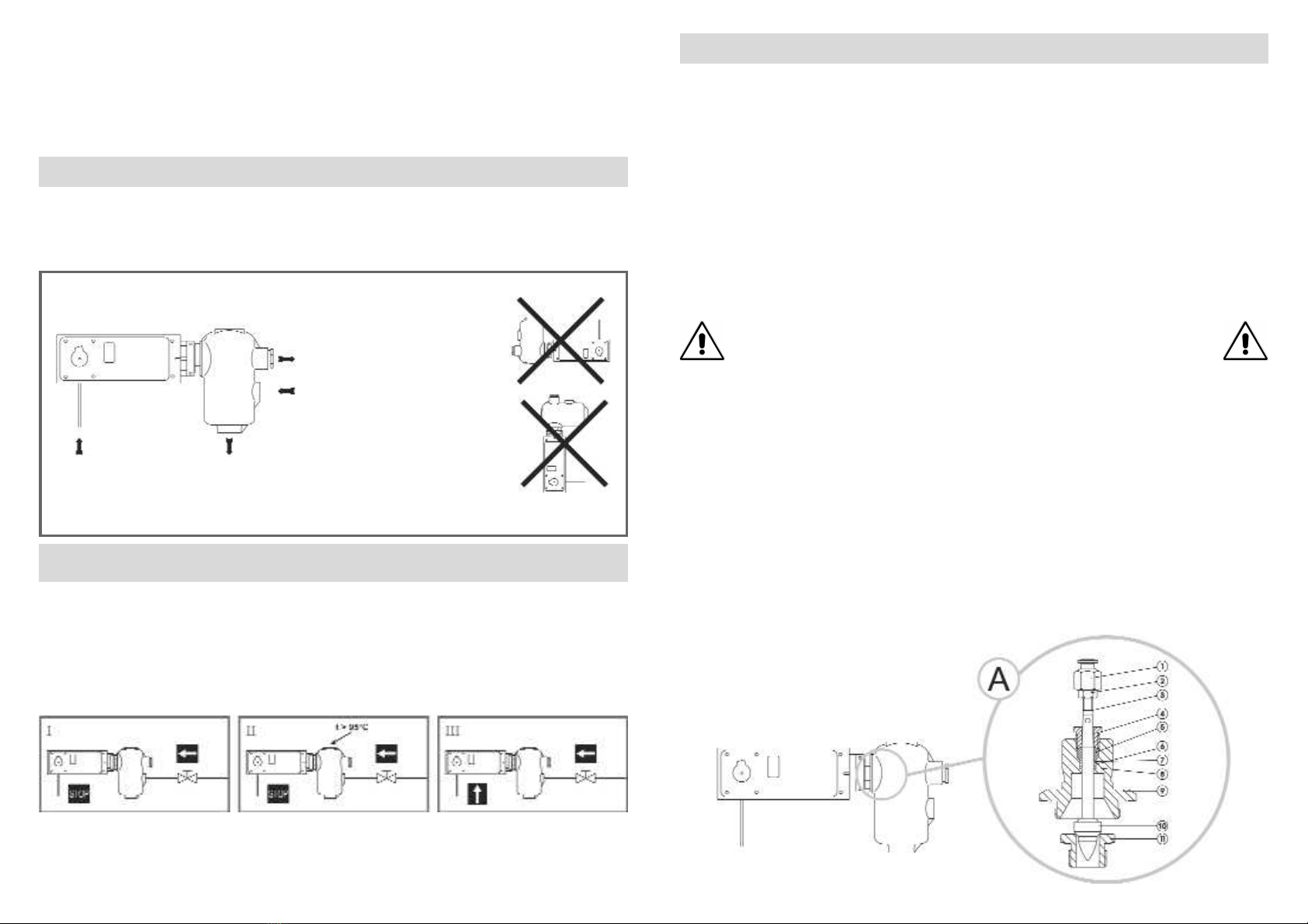
I. Austausch Ventil und Ventilsitz:
Anmerkung: bei Typ AM-1000 ist der Antrieb direkt auf das Luftbefeuchtergehäuse
aufgeschraubt (keine Verbindungsstück).
- Antrieb von Verbindungsstück abnehmen (A);
- Verbindungsstück (9) und alle verbundenen Teile abschrauben und entfernen;
- Ventilsitz (11) herausschrauben und erneuern;
-Stangeadapter (1) und Mutterstange (2) vom Ventilschaft (3) abschrauben;
- Stopfbüchse (4) herausschrauben und Packung (5), erste Dichtung (7),
Distanzscheibe (6) und zweite Dichtung (8) herausnehmen;
- Packungssatz erneuern durch Einsetzen der Teile (5, 6, 7 and 8) in umgekehrter
Reihenfolge, die Dichtungen (7 und 8) mit gewölbter Fläche nach unten;
- Stopfbüchse (4) wieder einschrauben;
- Einheit Ventilschaft (3) und Ventilsitz (11) einsetzen. Ventil (10) und Sitz (11)
sind geläppt;
- Stangeadapter(1) und Mutterstange (2) wieder auf Ventilschaft (3) aufschrauben;
- Verbindungsstück und alle verbundenen Teile wieder einschrauben (A).
-Antrieb mit Verbindungsstück (A) zusammenbauen. Ventilhub soll 19 mm
betragen.
- Dichten Abschluß des Ventils überprüfen. Wenn erforderlich,
Armstrong wegen der Einstellung des Antriebes kontaktieren.
Armstrong Steam Humidifiers can be delivered without operator, but in that case we do not have any responsibility for its assembly and its setup.
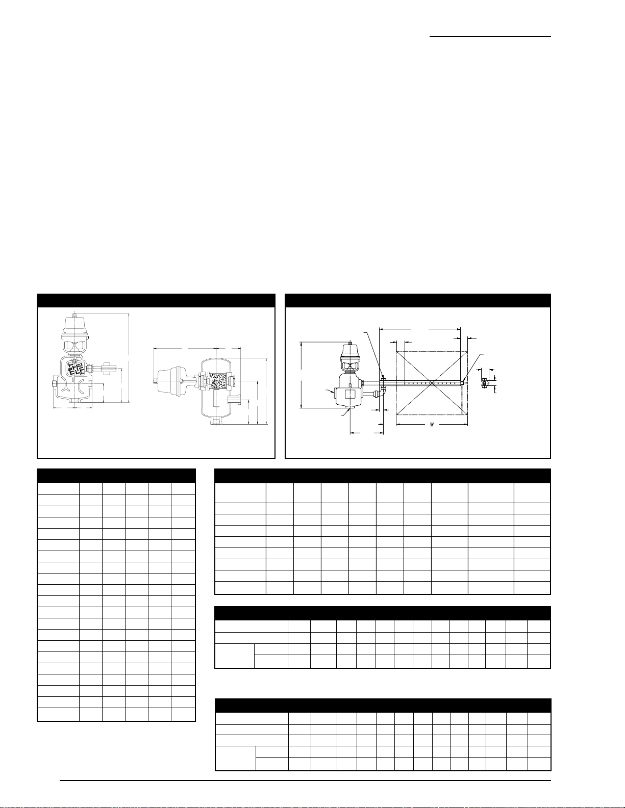
For detailed material specifications, approximate dimensions and weight, see Armstrong literature or consult your local Representative.
Armstrong Dampfluftbefeuchter sind auch ohne Antrieb lieferbar, wir übernehmen dann jedoch keine Verantwortung für die Montage und
Einstellung.
Für detaillierte Werkstoffangaben, Zubehör, Abmessungen und Gewichte, sehen Sie die Armstrong Datenblätter oder fragen Sie Ihre Armstrong-
Vertretung.
Les humidificateurs Armstrong peuvent être livrés sans servo-moteur ; dans ce cas, Armstrong se décharge de toute responsabilité concernant
l'assemblage et le réglage des opérateurs.
Pour toute spécification détaillée des matières, options, dimensions et poids, veuillez vous référer à la littérature Armstrong ou prendre contact
avec votre Représentant local.
Series EM-1000 & AM-1000
Steam Humidifiers
Dampfluftbefeuchter
Humidificateurs Armstrong
Humidificadores de Vapor
Stoombevochtigers
Umidificatori a Vapore
These instructions should be used by experienced personnel !
Diese Gebrauchsanweisung ist durch Fachpersonal zu benutzen !
Ces instructions devraient être utilisées par du personnel expérimenté !
¡Estas instrucciones deben ser utilizadas por personal experimentado !
Onderhoud uitsluitend uit te voeren door ervaren personeel !
Queste istruzioni devono essere utilizzate da personale esperto !
Model shown on the picture: BELEM-1100 - Die Abbildung zeigt das Modell BELEM-1100 - Photo: modèle BELEM-1100
Modelo mostrado en la fotografía: BELEM-1100 - Model op foto: BELEM-1100 - Modello in figura: BELEM-1100
Armstrong Stainless Steel Steam Humidifiers
Delivered with Inverted Bucket Steam Trap and "Y"-Type
Strainer, Assembled with Pneumatic or Electrical Actuator,
For Steam Distribution in Ducts (Through Manifolds)
Optional: Temperature Switch to Guarantee Discharge of Dry Steam Only
Armstrong Dampfluftbefeuchter aus Edelstahl mit
Glockenkondensatableiter und Y-Schmutzfänger,
Aufgebautem Pneumatischen oder Elektrischen Antrieb, zur
Einbringung von Dampf in Lüftungskanäle (durch Verteilrohre)
Option: Ein Thermostat Garantiert ausschließlich die Einbringung von Trockendampf
Humidificateur à Vapeur Armstrong en Acier Inoxydable. Livré avec Purgeur à Flotteur Inversé Ouvert et Filtre "Y". Monté avec
Servo-Moteur Pneumatique ou Électrique, Injection de Vapeur dans les Gaines de Conditionnement d'Air (Rampes d'Injection)
En option : Thermostat de Sécurité pour Garantir une Injection de Vapeur Sèche Uniquement
Humidificadores Armstrong en Acero Inoxidable. Se Entregan con Purgadores de Cubeta Invertida y Filtros Tipo "Y".
Montados con Actuador Neumático o Eléctrico. Para la Distribución de Vapor en Conductos (a Través de Manifolds)
Opcional: Termostato para Garantizar la Descarga de Vapor Seco Únicamente
Armstrong Stoombevochtigers uit Roestvrijstaal. Geleverd met Omgekeerde-Emmer Kondenspot en "Y"-Type Filter.
Voorzien van Pneumatische of Elektrische Aandrijving. Voor Stoomdistributie in Luchtkanalen (Middels Spreidingsbuizen)
Optioneel: Blokkeringsthemostaat Garandeert het Vrijkomen van Alleen Droge Stoom
Umidificatore a Vapore - in Acciaio Inossidabile. Fornito con Scaricatore di Condensa e Filtro di Linea a Y. Assemblato con
Attuatore Pneumatico o Elettrico. Per Distribuzione Vapore in Condotte o Centrali Trattamento Aria (Con Distributori)
Accessori opzionali: Termo-interruttore di Temperatura per Assicurare Distribuzione di Vapore Secco
Armstrong Steam Humidifiers can be delivered without operator, but in that case we do not have
any responsibility for its assembly and its setup.
Armstrong Dampfluftbefeuchter sind auch ohne Antrieb lieferbar, wir übernehmen dann jedoch keine
Verantwortung für die Montage und Einstellung.
Les humidificateurs à vapeur Armstrong peuvent être livrés sans servo-moteur. Dans ce cas, Armstrong se décharge
de toute responsabilité concernant l'assemblage et le réglage de ces opérateurs.
Los humidificadores de vapor Armstrong pueden entregarse sin actuador pero, en ese caso, no nos hacemos
responsables por su montaje y puesta en marcha.
Armstrong stoombevochtigers kunnen geleverd worden zonder aandrijving, in dat geval is Armstrong niet
aansprakelijk t.a.v. samenbouw en gebruikte instellingen
Gli umidificatori Armstrong possono essere forniti senza attuatori e solo eventualmente predisposti per il loro
assemblaggio. In tal caso la Armstrong declina qualsiasi responsabilità relativamente agli stessi attuatori, al loro il
successivo assemblaggio sugli umidificatori ed alla loro taratura operativa.
PRODUCT DESCRIPTION - PRODUKTBESCHREIBUNG - DESCRIPTION DU PRODUIT
DESCRIPCION DEL PRODUCTO - PRODUKT OMSCHRIJVING - DESCRIZIONE DEL PRODOTTO
Armstrong International S.A., Parc Industriel des Hauts-Sarts, 4040 Herstal - Belgium Ph: +32.4.240.90.90 Fax: +32.4.248.13.61
IOM-1041-B 10/2005 www.armstrong.be Printed in Belgium
I. Remplacement de l'ensemble siège-soupape :
Note: pour la série AM-1000, le servo-moteur est directement vissé sur le corps
de l'humidificateur (il n'y a pas d’accouplement).
- Retirer le servo-moteur de l’ensemble d’accouplement (bonnet) (A);
- Dévisser et enlever l’accouplement (9) et toutes les pièces qui y sont associées;
- Dévisser et remplacer le siège (11);
- Désolidariser l'accouplement de tige (1) et l'écrou (2) de la tige (stem) (3);
- Dévisser la presse étoupe (4) et enlever le bourrage (5), la première rondelle (7),
l’entretoise (6) et la deuxième rondelle (8);
- Remplacer l’ensemble de bourrage en replaçant les parties (5, 6, 7 and 8) dans
l'ordre contraire, les rondelles (7 and 8) doivent être placées avec le ressort vers
le bas. Revisser la presse étoupe (4);
- Remplacer la tige (3) et le siège (11). La soupape (10) et le siège (11) sont rodés
ensemble;
- Revisser l’accouplement de tige (1) et l'écrou (2) sur la tige (3);
- Revisser l’accouplement et toutes les pièces qui y sont associées (A);
- Remonter le servo-moteur sur l'ensemble d’accouplement (A). La course de la
vanne modulante doit être de 19 mm;
- S'assurer que la soupape soit bien étanche en position fermée.
Si nécessaire, consulter Armstrong pour le réglage du servo-moteur.
I. Sostituzione valvola e sede:
Nota: per la serie AM-1000, l'attuatore è avvitato direttamente sul corpo dell'
umidificatore (non c'è alcun bonnet).
- Scollegare l'attuatore dal bonnet (A);
- Svitare e smontare il bonnet (9) e tutte le parti ad esso annesse;
- Svitare e sostituire la sede (11);
- Smontare l'adattatore (1) ed il dado (2) dallo stelo (3);
- Svitare il premistoppa (4) ed estrarre la treccia di tenuta (5), il primo anello di
tenuta (7), il distanziale (6) ed il secondo anello di tenuta (8);
- Sostituire l'intero set di tenuta (5, 6, 7 e 8) in ordine opposto, le tenute (7 e 8)
devono essere posizionate con la molla rivolta verso il basso. Riavvitare il
premistoppa (4);
- Sostituire lo stelo (3) e la sede (11). La valvola (10) e la sede (11) sono lappate;
- Riavvitare l'adattatore (1) ed il dado (2) sullo stelo (3);
- Riavvitare il bonnet e tutte le parti ad esso annesse (A).
- Riassemblare l'attuatore con il bonnet (A). La corsa della valvola deve essere
di 19 mm;
- Assicurarsi che la valvola chiuda perfettamente. Se necessario
contattare la Armstrong o il distributore locale per l'eventuale taratura
dell'attuatore.
I. Cambio de válvula y asiento:
Nota: para la serie AM-1000, el actuador se rosca directamente en el cuerpo del
humidificador (no lleva bonete).
- Retire el actuador del conjunto de bonete (A);
- Afloje y retire el bonete (9) y todas las piezas sujetas a él;
- Desajuste y cambie el asiento (11);
- Retire el adaptador (1) y la tuerca (2) del vástago (3);
- Afloje el prensaestopas (4) y quite la empaquetadura (5) y el primer sello (7), el
separador (6) y el segundo sello (8);
- Cambie el juego de empaquetaduras colocando las piezas (5, 6, 7 y 8) en orden
inverso; los sellos (7 y 8) deben quedar con el muelle mirando hacia abajo. Vuelva
a ajustar el prensaestopas (4);
- Cambie el conjunto de vástago (3) y asiento (11). La válvula (10) y el asiento
(11) están pulidos;
- Vuelva a ajustar el adaptador (1) y la tuerca (2) en el vástago (3);
- Coloque nuevamente el bonete y todas las piezas sujetas a él (A);
- Monte el actuador con el conjunto de bonete (A). La válvula deberá tener un
desplazamiento de 19 mm;
- Asegúrese de que la válvula cierra firmemente. Si fuera necesario,
consulte con Armstrong para la puesta en marcha del actuador.
Vervangen van klep en klepzitting:
N.B.: voor de serie AM-1000 is geen bonnet benodigd. De aandrijving is direkt op het
huis geschroefd.
- Verwijder de aandrijving van de klepassembly (A);
- Verwijder het koppelstuk (9) middels losschroeven en alle daaraan geassembleerde
onderdelen;
- Schroef de zitting (11) los en vervang deze ;
- Verwijder de klepsteel moer (1) en de klepsteel borgmoer (2) van de klepsteel (3);
- Schroef het pakkingsdrukstuk (4) los en verwijder de pakking (5) en de eerste
afdichting (7), de dichtingsring (6) en de tweede afdichting (8);
- Vervang de complete pakkingset door nieuwe onderdelen (5, 7, 6 and 8) in
omgekeerde volgorde te monteren, de afdichtingen (7 en 8) moeten geïnstalleerd
worden met de veer naar beneden gericht. Zet pakkingsdrukstuk (4) weer vast;
- Vervang de klepsteel (3) en zitting (11). Regelventiel (10) en zitting (11) zijn gepolijst;
- Schroef de klepsteel moer (1) en de klepsteel borgmoer (2) op de klepsteel (3);
- Schroef de bonnet en alle geassembleerde onderdelen terug op het huis (A).
- Monteer de aandrijving met de klepassembly (A). De slag van het regelventiel moet
19 mm zijn;
- Controleer of het regelventiel goed sluit. Indien nodig neemt u contact op
met uw Armstrong vertegenwoordiging voor de juiste instelling.
I. Valve and Seat Replacement:
Note: for the series AM-1000, the operator is directly screwed on the humidifier’s
body (there is no bonnet).
- Remove the operator from the bonnet assembly (A);
- Unscrew and remove the bonnet (9) and all the parts assembled to it;
- Unscrew and replace the seat (11);
- Disassemble the stem adapter (1) and the stem nut (2) from the stem (3);
- Unscrew the packing gland (4) and remove the packing (5) and the first seal (7),
the seal spacer (6) and the second seal (8);
- Replace the packing set by putting the parts (5, 6, 7 and 8) in the opposite order,
the seals (7 and 8) should be with the spring facing downward. Screw back the
packing gland (4);
- Replace the stem (3) and seat (11) assembly. Valve (10) and seat (11) are
lapped;
- Screw back the stem adapter (1) and the stem nut (2) on the stem (3);
- Screw back the bonnet and all the parts assembled to it (A);
- Assemble the operator with the bonnet assembly (A). The stroke of the valve
should be 19 mm;
- Make sure that the valve is closing tightly. If necessary, consult
Armstrong for operator set-up.

Signal from Humidistat
Signal von Hygrostat
Signal de l'humidistat
Señal del higrostato
Signaal van hygrostaat
Segnale dall'umidostato
Condensate Discharge to Steam Trap
Kondensatauslaß zum Kondensatableiter
Evacuation du condensat vers le purgeur
Descarga de condensado al purgador
Kondensaat afvoer naar kondenspot
Scarico condensa allo scaricatore
Low Pressure Steam Discharge to Manifold
Niederdruck - Dampfaustritt zum Verteilerrohr
Injection de Vapeur basse pression
(via la rampe de dispersion)
Descarga de vapor de baja presión al manifold
Lage druk stoom naar spreidingsbuis
Vapore in arrivo al distributore
(Pressione Atmosferica)
High Pressure Steam Inlet
Dampfeintritt Hochdruck
Entrée vapeur haute pression
Entrada de vapor de alta presión
Stoom onder toevoerdruk
Entratra vapore di rete (Alta Pressione)
Model shown on the drawing: BELEM-1100 - Die Zeichnung zeigt das Modell BELEM-1100 - Schéma: modèle BELEM-1100
Modelo mostrado en el dibujo: BELEM-1100 - Model op tekening: BELEM-1100 - Modello in figura: BELEM-1100
INSTALLATION - INSTALLATIONSANWEISUNG - INSTALLATION
INSTALACION - INSTALLATIE - INSTALLAZIONE
START-UP PROCEDURE - INBETRIEBNAHME - PROCEDURE DE DEMARRAGE
PROCEDIMIENTO DE PUESTA EN MARCHA - OPSTARTPROCEDURE - PROCEDURE D'AVVIAMENTO
Available with pneumatic or electrical operator - Erhältlich mit pneumatischem oder elektrischem Antrieb
Disponible avec servo-moteur pneumatique ou électrique - Disponible con actuador neumático o eléctrico
Verkrijgbaar met pneumatische- of elektrische aandrijving - Disponibile con attuatore pneumatico o elettrico
To shut the system down, the steam flow should be stopped before the operator's signal.
Bei Abschaltung des Systems zuerst Dampfzufuhr und dann Antriebssignal unterbrechen.
Pour l'arrêt du système, la vapeur doit être coupée avant le signal du servo-moteur.
Para apagar el sistema, el flujo de vapor se debe detener antes de la señal del actuador.
Buiten bedrijf stellen: stoomtoevoer dient afgesloten te zijn voordat signaal naar aandrijving afgesloten wordt.
Per fermare il sistema, bisogna chiudere il flusso del vapore, prima d'interrompere il segnale di comando all'operatore.
For detailed hookups and adapted start-up and shut-down procedures, see Armstrong literature or consult your local Representative.
Für detaillierte Informationen über Installation, Inbetriebnahme und Außerbetriebnahme sehen Sie die Armstrong Datenblätter oder fragen Sie Ihre
Armstrong-Vertretung.
Pour plus de détails à propos des procédures de démarrage et d'arrêt, ainsi que pour l'installation, veuillez vous référer à la littérature Armstrong
ou prendre contact avec votre Représentant local.
Para posibilidades de conexionado y procedimientos de parada y puesta en marcha, ver catálogos Armstrong o consultar con su Representante
local.
Voor gedetailleerde montage en installatie instructies zie het betreffende Armstrong documentatieblad of neem contact op met uw plaatselijke
Vertegenwoordiger.
Per procedure dettagliate di collegamento, d'avviamento e di fermata, vedere la documentazione Armstrong o consultare il Distributore locale.
MAINTENANCE - WARTUNGSINFORMATIONEN - MAINTENANCE
MANTENIMIENTO - ONDERHOUD - MANUTENZIONE
For troubleshooting, testing methods, frequency of maintenance and detailed spare parts list, see Armstrong literature or consult your local Representative.
Armstrong Steam Humidifiers can be delivered without operator, but in that case we do not have any responsibility for its assembly and its setup.
Für detaillierte Informationen über Fehlersuche, Testmethoden, Wartungsintervallen und Ersatzteillisten fragen Sie Ihre Armstrong-Vertretung.
Armstrong Dampfluftbefeuchter sind auch ohne Antrieb lieferbar, wir übernehmen dann jedoch keine Verantwortung für die Montage und Einstellung.
Pour le dépannage, les méthodes de test, la fréquence d'entretien et la liste détaillée des pièces de rechange, veuillez vous référer à la littérature Armstrong
ou prendre contact avec votre Représentant local.
Les humidificateurs Armstrong peuvent être livrés sans servo-moteur ; dans ce cas, Armstrong se décharge de toute responsabilité concernant l'assemblage
et le réglage des opérateurs.
Para detección de posibles averías, métodos de test, frecuencia de mantenimiento y lista detallada de repuestos, ver catálogos Armstrong o consultar con su
Representante local.
Los humidificadores de vapor Armstrong pueden entregarse sin actuador pero, en ese caso, no nos hacemos responsables por su montaje y puesta en marcha.
Voor het oplossen van problemen, test methodes, onderhoud en gedetailleerde onderdelenlijsten, zie de Armstrong documentatie of neem contact op met uw
plaatselijke Vertegenwoordiger.
Armstrong stoombevochtigers kunnen geleverd worden zonder aandrijving, in dat geval is Armstrong niet aansprakelijk t.a.v. samenbouw en gebruikte
instellingen.
Per la soluzione di eventuali problemi, metodi di prova funzionalità, frequenza di manutenzione e dettaglio della lista ricambi, vedere la documentazione
Armstrong o consultare il Distributore locale.
Gli umidificatori Armstrong possono essere forniti senza attuatori e solo eventualmente predisposti per il loro assemblaggio. In tal caso la Armstrong declina
qualsiasi responsabilità relativamente agli stessi attuatori, al loro il successivo assemblaggio sugli umidificatori ed alla loro taratura operativa
Equipement under pressure - Operating temperature > 100°C
Make sure humidifier is cold before handling !
Armatur steht unter Druck - Arbeitstemperatur >100°C
Stellen sie sicher, dass die Armatur kalt und drucklos ist, bevor an dieser gearbeitet wird !
Equipement sous pression - Température en fonctionnement > 100°C
Laisser l’humidificateur refroidir avant toute manipulation !
Equipo bajo presión - Temperatura de trabajo > 100°C
¡Asegúrese de que el humidificador esté frío antes de manipularlo !
Toestel onder druk - Werktemperatuur > 100°C
Stoombevochtiger moet afgekoeld zijn alvorens eraan te werken !
Apparecchiatura in pressione - Temperatura operativa > 100°C
Assicurarsi che l’umidificatore sia freddo prima d’intervenire !
Bonnet assembly shown on the drawing: BELEM-1100
Die Zeichnung zeigt Kappeneinheit BELEM-1100
Ensemble d’accouplement montré sur le schéma: BELEM-1100
Conjunto de bonete mostrado en el dibujo: BELEM-1100
Getoonde klepassembly: BELEM-1100
Bonnet in figura: BELEM-1100
Model shown on the drawing: BELEM-1100
Die Zeichnung zeigt das Modell: BELEM-1100
Schéma: modèle: BELEM-1100
Modelo mostrado en el dibujo: BELEM-1100
Model op tekening: BELEM-1100
Modello in figura: BELEM-1100
Los humidificadores de vapor Armstrong pueden entregarse sin actuador pero, en ese caso, no nos hacemos responsables por su montaje y puesta en marcha.
Para obtener especificaciones detalladas de materiales, opciones y dimensiones, y pesos aproximados, consulte los catálogos Armstrong o diríjase a su
Representante local.
Armstrong stoombevochtigers kunnen geleverd worden zonder aandrijving, in dit geval neemt Armstrong geen enkele verantwoording t.a.v. samenbouw en
gebruikte instellingen
Voor gedetailleerde materiaal specificaties, afmetingen en gewichten, zie de Armstrong documentatie of neem contact op met uw plaatselijke
Vertegenwoordiger.
Gli umidificatori Armstrong possono essere forniti senza attuatori e solo eventualmente predisposti per il loro assemblaggio. In tal caso la Armstrong declina
qualsiasi responsabilità relativamente agli stessi attuatori, al loro il successivo assemblaggio sugli umidificatori ed alla loro taratura operativa
Per la specifica dettagliata dei materiali, accessori opzionali, dimensioni e pesi approssimativi, vedere la documentazione appropriata o contattare il Distributore
locale.

Bulletin 544-I
Installation and Operation
Humidifiers for Air Handling Systems
AM-90M, -91M, -92M, -1200M, -93M, -1300M, -94M, -1400M;
HEM-90M, -91M, -92M, -1200M, -93M, -1300M, -94M, -1400M;
DSA-90, -91, -92, -93
Preliminary Procedures..............................................2
Do’s and Don’ts of Humidifier Installation..................3
Methods of Installing Humidifier.................................4
Installing and Piping the Humidifier...........................8
Multiple Manifolds......................................................9
Pneumatic Piping for Air Operated Models .............10
Wiring for Electrically Operated Models...................11
Operation and Servicing..........................................13
Page
Table of Contents
Steam humidifiers (or other products) should be installed in locations that allow routine inspection and accessibility
for maintenance operations. Armstrong recommends that steam humidifiers not be placed in locations where
unusual instances of malfunction of the humidifiers or the systems might cause damage to non-repairable,
irreplaceable, or priceless property.

2
These instructions cover the
installation of the models listed below:
Air Operated (AM):
90 - 94 Sizes (Cast Iron)
1200 - 1400 Sizes (Stainless Steel)
Electric Motor Operated (HEM):
90 - 94 Sizes (Cast Iron)
1200 - 1400 Sizes (Stainless Steel)
Electric “On-Off” (DSA):
90 - 93 Sizes (Cast Iron)
Preliminary Procedure
STEP 1: Check Shipment Against
Packing List. All components are
listed on the packing slip. Report any
shortages immediately. If the
humidifier or accessories have been
damaged in transit, notify us and file
claim with the transportation company.
If your order covers more than one
unit, separate each complete unit.
Humidifier tagging and manifold
tagging will be the same as shown on
the packing list. Model, Serial Number,
Steam Pressure, Orifice and Orifice
Restriction (if any) are on the metal
plate on the humidifier body. Operator
for electric motor operated unit is
shipped separately but marked with
the serial number of the humidifier
with which it must be used. Be sure
serial numbers agree.
STEP 2: Spot Humidifier Locations.
Locate each humidifier according to
the engineer’s layout or as indicated
by your Armstrong Representative. If
you must locate the humidifiers
yourself, be sure to read and observe
the “Do’s and Don’ts” on the following
page.
Manifold Installation
STEP 3: Cut Hole in Duct or Plenum
for Manifold. Use manifold
dimensions “X” and “Y” from Table 2-
2, below, and add approximately 1¼4"
for manifold clearance. If multiple
manifolds are used, read page 9 first.
STEP 4: Insert Manifold in Duct.
Outlet holes must point upstream into
air flow, except on insulated
manifolds point discharge holes
downstream. Where manifold is
positioned horizontally, use a spirit
level. Manifolds longer than one foot
should be supported. Put the two
piece manifold escutcheon plate in
position. When supporting the
manifold on the far end allow for
manifold expansion and contraction of
1/2" - 1”.
Instructions continued on page 8
Preliminary Procedure and Manifold Installation
Table 2-2. Cross-Section Dimensions
Model “N” “R” “S” “T” “X” “Y” Steam Condensate Alternate
Supply Drain Inlet
90 Size 53/8"2"1"1"1
1/4"1
7/8"1/2" NPT 1" 1/2"
91 Size 511/16"2"1"1"1
1/4"1
7/8"1/2" NPT 1" 3/4"
92 Size 89/16"2"1"1"1
3/4"2
5/8"3/4" NPT 1" 3/4"
1200 Size 89/16"2"1"1"1
3/4"2
5/8"3/4" NPT 1" 3/4"
93 Size 91/16"2" 1
5/8"1
5/8"2
1/8"3
1/8"1
1/4" NPT 11/4"1
1/4"
1300 Size 97/8"2"1
5/8"1
5/8"2
1/8"3
1/8"1
1/4" NPT 11/4"1
1/4"
94 Size 131/2"2" 1
5/8"1
5/8"3
1/4"4
1/4" 2" NPT 2" 2"
1400 Size 145/16"2" 1
5/8"1
5/8"3
1/4"4
1/4" 2" NPT 2" 2"
Table 2-1. Dimensions in Inches
Model No. B C D E F
AM-90 87/8–2
3/827/16 213/16
HEM-90 151/2–2
3/827/16 213/16
DSA-90 7 – 23/827/16 213/16
AM-91 16 33/831/16 61/16 313/16
HEM-91 191/233/831/16 61/16 313/16
DSA-91 107/833/831/16 61/16 313/16
AM-92 16 33/8313/16 61/16 313/16
HEM-92 191/233/8313/16 61/16 313/16
DSA-92 107/833/8313/16 61/16 313/16
AM-1200 103/8313/16 313/16 611/16 911/16
HEM-1200 103/8313/16 313/16 611/16 131/4
AM-93 191/845/843/494
3/4
HEM-93 223/445/843/494
3/4
DSA-93 141/245/843/494
3/4
AM-1300 163/465
9/16 105/16 1015/16
HEM-1300 163/465
9/16 105/16 143/16
AM-94 231/267/8812
5/88
HEM-94 281/267/8812
5/88
AM-1400 245/8815/16 85/16 1411/16 12
HEM-1400 245/8815/16 85/16 1411/16 161/2
Table 2-3. Manifold Lengths and Duct Widths With Which They May Be Used
Manifold Model No. M-1 M-1.5 M-2 M-3 M-4 M-5 M-6 M-7 M-8 M-9 M-10 M-11 M-12
(L) Length 12" 18" 24" 36" 48" 60" 72" 84" 96" 108" 120" 132" 144"
W - Duct (Min) 8" 15" 21" 31" 43" 53" 65" 77" 89" 101" 113" 125" 137"
Width (Max) 14" 20" 30" 42" 52" 64" 76" 88" 100" 112" 124" 136" 148"
Table 2-4. Model 90 Manifold Lengths and Duct Width With Which They May Be Used
Vertical Air Flow No. MV-1 MV-1.5 MV-2 MV-3 MV-4 MV-5 MV-6 MV-7 MV-8 MV-9 MV-10 MV-11 MV-12
Horizontal Air Flow No. MH-1 MH-1.5 MH-2 MH-3 MH-4 MH-5 MH-6 MH-7 MH-8 MH-9 MH-10 MH-11 MH-12
(L) Length 12" 18" 24" 36" 48" 60" 72" 84" 96" 108" 120" 132" 144"
W - Duct (Min) 8" 15" 21" 31" 43" 53" 65" 77" 89" 101" 113" 125" 137"
Width (Max) 14" 20" 30" 42" 52" 64" 76" 88" 100" 112" 124" 136" 148"
NOTE: Insulated manifolds available. Consult factory.
Figure 2-1. Humidifier Dimensions Figure 2-2. Steam Distribution Manifold Data
Sectional view of
Model 1200
Sectional view of AM9000. Model
EM9000 is similar except for
operator. See Table for dimensions.
See Page 14 for Mounting Hole Information.
E
C
DF
B
D
B
E
C
F
Alternate
Inlet
Condensate
Drain
B
S
N
(min)
T
(min)
L
R
(min)
W
X
1" Min.
Support for Manifold
(Not furnished on M-1 Size)
Y
Steam Supply

3
All recommendations for the application of Armstrong
Humidifiers are based on tests and field experience.
However, they are based on duct air velocities and
temperatures that are most commonly encountered, and the
recommendations may have to be modified when velocities
are very high and/or temperatures unusually low. We also
reserve the right to modify recommendations without notice
if subsequent tests or experience indicate that a change
should be made. For these reasons, we urge that you check
all applications with your Armstrong Representative before
installation.
Do’s and Don’ts of Humidifier Location and Installation
The 9000 & 1000 Series must always be perpendicular to the floor!
Fig. 3-1. Always select the steam
distribution manifold length that will span
the maximum width of duct. Fig. 3-5. Whenever possible, install
distribution manifold downstream from
coils. If more than 3' of distance between
manifold and coil on upstream side is
available, it is permissible to install at this
location.
Fig. 3-9. When it is necessary to place
humidifier discharge into a “packaged”
multi-zone air handling system, install
distribution manifold into center of active
air flow and as close to fan discharge as
possible.
Fig. 3-10. Always install distribution
manifold as far upstream from a discharge
air grille as possible—never less than 3'.
This also applies to elbows, splits,
transitions, ducts, etc.
Fig. 3-11. Dispersion manifold should
never be placed within 3' of an air fan
intake. The desirable location would be at
the fan discharge.
Fig. 3-12. Do not install manifold closer
than 5' upstream of temperature controller.
Fig. 3-6. Do not restrict air flow in ducts 8"
or less in depth. Utilize an expanded
section.
Fig. 3-7. Do not install the distribution
manifold less than 10' upstream from a
high efficiency filter. Locate high limit duct
humidity controller immediately upstream
from the filter.
Fig. 3-8. When it is necessary to place
humidifiers in coil section ahead of fan,
locate manifold in most active air flow and
as far upstream from fan inlet as possible.
Fig. 3-2. When possible, install the steam
distribution manifold into the center of duct.
Fig. 3-3. Manifold should never be
installed vertically downward from control
valve. This presents a condensate
drainage problem in the jacket of the
manifold. Vertically upward installation is
permissible.
Fig. 3-4. Always size and install dispersion
manifold to span the widest dimension of
the duct section.

4
Primary Methods of Installation
May be used with 91 - 94 Cast Iron, and 1200 - 1400 Stainless Steel Humidifiers
The standard method of installing Armstrong humidifiers is
with the humidifier body vertical (do NOT mount body
horizontally) and the manifold discharging into the air flow.
For operator orientation see manufacturer’s data. Pipe and
fittings indicated by dotted lines are furnished by installing
contractor. Dimensions and pipe sizes are given in
Tables 8-1 and 8-2 on Page 8.
Methods of Installing Humidifiers
OR
U Min.
N Min.
Manifold
Drip Leg
Dirt Pocket
Trap
Strainer
N Min.
Drip Leg
Dirt Pocket
Trap
U Min.
OR
Manifold
Pipe Adaptor
Insulate (Avoid Use of
Elbows or Extra Fittings)
Strainer
Figure 4-1. Horizontal Installation
Figure 4-2. Installation Method Where Obstructions Prevent Direct Manifold Connection
Note: Maximum distance recommended from humidifier to manifold is 5-10 feet.

5
OR
Manifold
Strainer
Manifold
Pipe Adaptor
Drip Leg
Dirt Pocket
Trap
Strainer
Supply Pipe
Manifold
OR
U Min.
Drip Leg
N Min.
Dirt Pocket
Trap
Figure 5-2. Installation Method Where
Vertical Manifold Installation is Required
Dimensions and pipe sizes are given in Tables
8-1 and 8-2 on Page 8.
Figure 5-1. Installation Detail for Horizontal Manifold Installation in Vertical Air Flow Ducts
Dimensions and pipe sizes are given in Tables 8-1 and 8-2 on Page 8.

6
Supply Pipe
Strainer
Trap
Drip Leg
Dirt Pocket
U Min.
Manifold
N Min.
Strainer
Humidifier Body
with Operator and
Integral Control Valve
Inverted Bucket
Steam Trap
Copper Tubing
(Model 90)
Union Ell
(Models 91-94
and 1200-1400)
Manifold
Manifold
Escutcheon
Plate
Manifold Coupler Nut
with Washer and O-Ring
Figure 6-2. Components Furnished as Part of a Standard Single Manifold Installation
Dimensions and pipe sizes are given in Tables 8-1 and 8-2 on Page 8.
Figure 6-1. Model 90 Installation Method
Dimensions and pipe sizes are given in Tables 8-1 and 8-2 on Page 8.

7
Alternate Method of Installation
Chart 7-1.
Manifold Size Manifold Steam Pipe Adapter AB
Jacket Conn. Size Connection Size
90 1/2" NPT 1/2" NPT 21/8"4
1/2"
91 1/2" NPT 1/2" NPT 21/8"4
1/2"
92/1200 3/4" NPT 3/4" NPT 21/8"8
3/4"
93/1300 11/4" NPT 1" NPT 23/8"8
3/4"
94/1400 2" NPT 2" NPT 31/2" 10"
Manifold Pipe Adaptor
Steam Inlet Connection
B
ASteam Jacket Connection
Manifold
Figure 7-2. Connection size and dimensions of manifold with pipe adaptor
Trap
Outlet
Temperature
Switch
Inlet Strainer
Dirt Pocket
Drip Leg
Manifold
Pipe Adaptor
Manifold
OR
Figure 7-1. Vertical Installation
Dimensions and pipe sizes are given in
Tables 8-1 and 8-2 on Page 8.

8
Installing and Piping the Humidifier
STEP 5: Provide Support for Humidifier Body
Suspension from the ceiling is usually best. In all models
except 90 and 91 sizes, there are flanged holes near the top
of the humidifier body for mounting purposes. See drawing on
Page 14.
STEP 6: Bring Steam Supply to the Manifold as shown in
drawings at right. Be sure steam supply corresponds to
pressure stamped on humidifier. Do NOT use smaller pipe
sizes than shown in the table below for any connections. Take
steam supply line from the top of the supply main—never from
the side or bottom. See Steam Pipe Capacities on Page 14.
Expansion and Contraction. With average length of supply
line, the dimension change from hot to cold should not exceed
2". Provide piping with 3 elbows to get swing to take care of
expansion and contraction.
STEP 7: Connect Manifold to Humidifier as shown at the
left for the installation method you are using., Piping shown in
dotted lines is provided by the contractor. Unthreaded pipe,
size as per above, is used with the slip fitting on body. Do not
insert manifold or pipe more than 1.5" into body as measured
from face of manifold coupler nut. See Figure 9-1.
STEP 8: Install Drip Leg and Armstrong Inverted Bucket
Steam Trap. Connect to low pressure return. NEVER connect
to return line carrying condensate from high pressure traps.
Table 8-1. Basic Dimensions of Installation Methods
Shown in Figure 5-1 and 5-2.
Humidifier Size M N U
Min. Min.
90 or DSA-90-M - 53/8" 10"
91 or DSA-91-M 25/8"5
11/16"13
1/4"
92/1200 or DSA-92-M 23/4"8
9/16"13
1/4"
93/1300 or DSA-93-M 43/8"8
9/16" 24"
94/1400 55/8"12
1/2" 28"
Table 8-2. Recommended Pipe Size
Humidifier Size Supply Strainer to Manifold Drip Trap
Header to Manifold to Body Leg Piping
Strainer Inlet
90 or DSA-90-M 1/2"1/2"1/2"1"
1/2"
91 or DSA-91-M 3/4"1/2"1/2"1"
3/4"
92/1200 or DSA-92-M *3/4"3/4"3/4"1"
3/4"
93/1300 or DSA-93-M *11/4"1
1/4"1
1/4"1
1/4"3/4"
94/1400 2" 2" 2" 2" 3/4"
*When steam supply is less than 5 psi use one pipe size larger.
Note: Pitch supply piping to humidifier, 1/2" in 10 feet.
Drain and trap runouts exceeding 30 feet in length.
Avoid sags in piping.
Ream pipe and blow out at full steam pressure before connecting to
humidifier.
Figure 8-1. Typical Runout at End of Header
Figure 8-2. Long Runout
Figure 8-3. Runout with Pressure Reducing Valve
Figure 8-4. Single Runout to Multiple Humidifiers
Figure 8-5. Models 93/1300 and 94/1400 High Capacity vs. Low Capacity Piping Options
Steam Supply and Condensate Drainage Piping for the
Armstrong Humidifier

9
Multiple Manifolds
Multiple Manifolds – See Page 7 for required pipe sizes and dimensions of manifolds with pipe adapter.
Piping Multiple Manifolds – Figure 9-3 below shows the standard installation of reduced size manifold. Note the steam
jacketing is trapped separately and the steam discharge is into a tee, not a cross. A cross will
cause uneven steam distribution from manifold to manifold.
When same size manifolds (as the
separator) are used, the piping can
eliminate the drain trap from the
manifold jacket. Note that steam now
discharges into an elbow, not a cross,
and that the manifold steam jackets
are not trapped separately.
Note: The humidifier steam inlet is
below the bottom manifold. If the
bottom manifold is below the
humidifier inlet, piping should be as in
Figure 9-3.
Note: When steam supply pressure is
less than 10 psig and total length of
manifolds is greater than 20 feet, trap
manifolds separately as shown in
Figure 9-3.
Chart 9-1. Header Size of Manifold Piping Out of Humidifier
Separator Minimum Suggested
Size Pipe Size Header Size
90 1/2"3/4"
91 1/2"2"
92/1200 3/4"2
1/2"
93/1300 1" 3"
94/1400 2" 5"
Humidifier discharge piping, even with reduced sized
manifolds must be as shown.
Figure 9-2. Manifold Pipe AdaptorFigure 9-1. Pipe Connection at Humidifier
Figure 9-3. Piping of Reduced Size Manifolds
Figure 9-4. Piping of Same Size Manifold When All Manifolds Are Above Humidifier Inlet

10
Pneumatic Piping for Air Operated Humidifier–AM Models
STEP 9A: Install Pneumatic Piping
in accordance with Fig. 10-1 or
engineer’s layout.
a. Control Air Supply. Unless
otherwise specified, air supply for
Armstrong Humidifiers should be 20
psig maximum. This air must be
clean and dry.
b. Air Piping. 1¼4" plastic tubing or
equivalent is recommended for all
air connections.
Note: When a pilot positioner is
furnished, it should be hooked up as
shown in Fig. 10-3.
STEP 10A: Install and Connect
Humidity Controller as specified by
engineer in accordance with
manufacturer’s instructions. If location
is not specified it may be installed in
the area controlled or in either the
return air or exhaust air ducts.
Auxiliary Controls
Hi-Limit Duct Humidity Controller. A
high limit humidistat is recommended
in the duct at least 10 feet
downstream from the humidifier to
override the controlling humidistat.
This high-limit humidistat automatically
prevents local saturation at the point of
steam introduction. It also prevents
overloading the duct with vapor in the
event of failure of air conditioning
system components, incorrect control
settings or tampering. See Fig. 10-1.
Interlocks for Shutdowns.
Humidifiers should be interlocked with
fans for shutdown on power failure or
other system trouble. Interlock should
be such that the valve will go to the
closed position on a system shutdown
rather than be locked in its position at
time of shutdown. See Figure 10-2.
Temperature Switch for Automatic
Warm Up. For systems that may be
started and stopped, such as in
laboratories or in operations which
shut down each weekend, a
temperature switch is recommended
on the condensate outlet from the
humidifier. Your Armstrong
Representative can supply an
immersion type unit that will
automatically keep valves closed
during warm up period after shutdown.
This will avoid the discharge of
condensate that can occur if steam is
admitted to cold humidifier piping
when the humidifier valve is open See
Fig. 10-1.
Figure 10-1. Standard compressed air hook-up for all pneumatically
operated humidifiers. Pneumatic temperature switch shown.
Figure 10-3. Compressed air hook-up for humidifiers utilizing a
Honeywell MP953-F pneumatic operator with pilot positioner.
Figure 10-4. Compressed air hook-up for humidifiers utilizing two
Armstrong Duct Humidity Controllers, one as the humidity controller,
the other as a high limit controller.
Figure 10-2. Compressed air hook-up for air operated humidifiers
incorporating safety interlock for shutdown in the event of power failure
to fan and an electric temperature switch to prevent water discharge on
start-up when humidifier piping is cold.

11
Wiring for Electrically Operated Humidifiers–EM Models
EM Models
STEP 9E (EM): Make Electrical
Connections as recommended by the
manufacturers of the operators and
controls.
“EM” Series electric motor operated
humidifiers are furnished with a choice
of Honeywell M9182A operators,
Barber-Coleman MP361 or MP461, or
Belimo AF24SR or NVF24 electric
motorized operators. These operators
may be controlled by compatible
humidity controllers or electronic
humidity panels.
For all EM operators, mount
operator so that the motor shaft is
horizontal to the floor.
STEP 10E (EM): Install Temperature
Switch. Remove cover of switch for
access to adjustable mounting strap.
Strap the switch to the humidifier drain
line piping just ahead of the steam
trap.
Solenoid Models
(DSA Models)
STEP 9E: Make Electrical
Connections as diagrammed in Fig.
11-2. Be sure wiring is adequate for
the requirements of the system. Check
voltage ratings on operator nameplate.
STEP 10E: Install and Wire Humidity
Controller as specified by the design
engineer and in accordance with
manufacturer’s instructions. If location
is not specified, the controller may be
installed in area controlled or in either
the return air or exhaust air ducts.
STEP 11E: Install Temperature
Switch. Remove cover of switch for
access to adjustable mounting strap.
Strap the switch to the humidifier drain
line just ahead of the steam trap.
STEP 12E: Check Out Solenoid
Valve. After making electrical
connections, move the humidity
setting indicator of the humidistat back
and forth past the point corresponding
with the actual room humidity. You
should be able to hear the solenoid
valve click open and click shut. For
test purposes a jumper will have to be
used on the temperature switch
connections since the function of this
switch is to prevent energizing the
solenoid until the humidifier reaches
steam temperature.
Auxiliary Controls
for All Models
Hi-Limit Duct Humidity Controller.
An enclosed switch type high limit
humidistat is recommended in the duct
at least 10 feet downstream from the
humidifier to override the controlling
humidistat. It is particularly
recommended with on/off models. This
high limit humidistat automatically
prevents local saturation at the point of
steam introduction. It also prevents
overloading the duct with vapor in the
event of failure of air conditioning
system components, incorrect control
settings or tampering.
Interlocks for Shudowns.
Humidifiers should be interlocked with
fans for shutdown on power failure or
other system trouble. Interlock should
be such that valve will go to the closed
position on a system shutdown rather
than be locked in its position at time of
shutdown.
Temperature Switch for Automatic
Warm Up. This is a strap-on type and
is connected to the interlock system to
automatically keep valves closed
during warm up period after shutdown.
This will avoid the discharge of
condensate that can occur if steam is
admitted to cold humidifier piping
when the humidifier valve is open.
HC-201 High Limit Duct
Humidity Controller
(when used)
Temp. Switch
120 V. or 240 V.
24 V.
Transformer
M9182A (Series 90)
Motorized Operator
O
T
T
B
B
B
R
R
R
W
W
H915A (Series 90)
Humidity Controller
If High Limit Not Used
Wire R Directly to R
HC-201 High Limit Duct Humidity
Controller (Set at 90%)
(Used enclosed type switch)
Temp.
Switch
Solenoid
Interlock with Fan System
120 V. or 240 V. Single Phase
HC-101 Humidity Controller
Figure 11-1. Wiring diagram for HEM Series humidifiers using Honeywell M9182A
operator and H915A potentiometer controller.
Figure 11-2. Wiring diagram for 120v or 240v Solenoid
model humidifier. Wiring for auxiliary high limit duct
humidity controller and interlock for system shutdown is
shown in dotted lines.
NOTE: For wiring data covering Barber-Coleman operators, contact the factory or your Barber-Coleman dealer.

12
A9023
Pressure
Switch
(Optional)
Belimo AF24-SR
or NVF24-MFT-E
A8581
High Limit
Humidistat
(Optional)
Armstrong
0 - 10 VDC Stat
A18609 or A18610
B1564
Electric
Temperature
Switch
(Optional)
24 VAC
Transformer
Line Voltage
Figure 12-1. Wiring diagram for BLEM or BNVEM Series Humidifiers Using Armstrong 0-10 VDC Humidistats
A9023
Pressure
Switch
(Optional)
Armstrong
0 - 10 VDC Stat
A18609 or A18610
B1564
Electric
Temperature
Switch
(Optional)
Honeywell M9182A
with Q7230 Module
Line Voltage
24 VAC
Transformer
A8581
High Limit
Humidistat
(Optional)
Figure 12-2. Wiring diagram for HEM Series Humidifiers Using Armstrong 0-10 VDC Humudistat

13
How Duct Type Humidifiers Work
After passing through the Armstrong
inline strainer, steam supply enters the
steam jacket of the manifold and
circulates around the distribution pipe.
Steam now enters the cast iron steam
separating chamber. The use of cast
iron as a separator is probably the
single most important feature in the
Armstrong humidifier design.
The preferred material of strength and
durability, cast iron gives Series 9000
humidifiers flexibility in design without
fabrication. In addition, castings mean
better heat retention because of
thicker walls. Which in turn means a
lower rate of condensation.
Entering the main separating chamber,
steam encounters a cupped baffle
which reverses its flow and turns it
back on itself. The outer walls of the
casting form another cup, and the
same thing happens again. These two
180° turns help condition the steam,
reducing its volume and separating the
condensate from the vapor.
Condensate from supply and radiation
and most of the particulates in the
steam not removed by the strainer
collect in the large drain leg and are
discharged through the inverted
bucket drain trap.
Steam from the separating chamber
flows around and through the valve
which is actuated by a demand signal
from the humidistat.
Next the steam flows into the drying
chamber which is jacketed by the
separating chamber. The drying
chamber is filled with a stainless steel
silencing material which almost
completely absorbs the noise of
escaping steam
How air-operated units work.
Air-operated units operate in the same
manner as electric units except that
they utilize a pneumatic humidistat as
humidity controller in the space and an
air operator to open and close the
steam valve.
Explosion hazard
humidification.
Sizing air-operated humidifiers for
areas where an explosion hazard
exists is done exactly as for other
requirements except that they should
be sized for the most severe
conditions of makeup air, RH required
and minimum steam pressure.
Putting the Humidifier
Into Operation
When Temperature Switch Is
Employed simply set humidity
controller at desired level, and turn on
the steam.
When Temperature Switch Is Not
Employed deactivate operator control
so that humidifier control valve will
remain closed. Then:
A. Open steam supply valve to bring
humidifier up to temperature.
B. When drain line from humidifier is
at steam temperature, activate the
operator control.
C. Set desired relative humidity.
After the Humidifier
Is In Operation
Clean Strainer. The screen in the
strainer installed in the steam supply
line should be cleaned a few days
after the humidifier is placed in
operation, and thereafter at least once
each season—more often if you find
much dirt in the screen.
Check Trap. The steam trap used to
drain the humidifier should be
inspected at the same time the
strainer is cleaned.
Trouble Shooting
Humidifier Will Not
Discharge Steam
A. Control System at Fault.
1. Faulty control valve operator.
2. Faulty humidity controller.
3. Faulty connections between
humidity controller and control
valve operator.
B. Steam System Malfunction.
1. Silencing chamber plugged with
dirt. Remove and replace
silencing material and retainer.
2. Strainer screen plugged.
3. Dirt in steam line.
4. Steam valve closed in line to
humidifier.
5. Pressure reducing valve out of
order.
Humidifier Discharges Water
A. Faulty Steam Supply.
1. Long, untrapped suppy line.
2. Humidifier supply from bottom or
side of steam header.
3. Untrapped valve in vertical,
down feed supply line.
4. Boiler carryover.
B. Faulty Drainage.
1. Steam trap filled with dirt.
2. Return line pressure above
humidifier pressure.
3. Too much vertical lift.
4. Wrong type of drain trap used.
Always use the Armstrong
Inverted Bucket Steam Trap.
C. Faulty Operation.
1. Faulty temperature switch.
2. Humidity controller set up before
humidifier has reached steam
temperature.
Humidifler Discharges
Continuously even though
humidity has reached desired level.
A. Humidity controller out of
calibration.
B. Trouble in Humidifier
1. Valve stem “frozen” to stem seal
due to unusual chemical or
corrosive conditions in steam
system.
2. Operator spring broken.
3. Dirt or scale between valve and
seat.
Operating and Servicing
Figure 13-1. How Armstrong Conditioned Steam Humidifiers operate for air handling
humidification
Steam jacketed valve
positioned by
controller
Silencing
chamber
Steam jacketed
drying chamber
Separating
chamber
Abrupt change in
flow
Condensate formed in
supply line knocked
down by baffle
Steam at supply pressure
Steam at atmospheric
pressure
Condensate
Steam
jacketed
manifold
Steam supply

Humidifier Dimensions (Continued from page 2)
Steam Pipe Capacities
For computing ability of piping to deliver an adequate supply of steam to humidifier.
Capacities shown are in pounds per hour.
14
Steam humidifiers (or other
products) should be installed in
locations that allow routine
inspection and accessibility for
maintenance operations.
Armstrong recommends that steam
humidifiers not be placed in
locations where unusual instances
of malfunction of the humidifiers or
the systems might cause damage
to non-repairable, irreplaceable, or
priceless property.
Table 14-1. Mounting Hole Sizes
Model A B C D E F G
91 5/8"3/8"-16 11/32"7/16" Dia. 2" 33/16"—
92 5/8" UNC .56 11/32"Thru 21/2"3
3/16"—
93 5/8" Deep 1/2"Hole 23/4"3
15/16"—
94 ——— 3
7/8"6
9/16"3
11/16"
Table 14-2. Steam Pipe Capacity at 5 psi
Pressure drop, psi per 100 ft.
Pipe Size of pipe length
In. 1/81/41/23/41
1 2431445462
11/452 68 97 120 140
11/281 100 150 180 210
2 160 210 300 370 430
21/2270 350 500 610 710
Table 14-3. Steam Pipe Capacity at 15 psi
Pressure drop, psi per 100 ft.
Pipe Size of pipe length
In. 1/81/41/23/412
1 2738536576110
11/459 83 120 140 160 230
11/291 130 180 220 260 360
2 180 260 370 450 520 740
21/2300 430 600 740 860 1210
Table 14-4. Steam Pipe Capacity at 25 psi
Pressure drop, psi per 100 ft.
Pipe Size of pipe length
In. 1/81/41/23/412
3/415 21 30 37 43 60
1 3043617586122
11/467 95 130 160 190 260
11/2100 140 210 250 290 410
2 210 300 420 510 590 840
21/2340 490 690 850 980 1380
Table 14-5. Steam Pipe Capacity at 50 psi
Pressure drop, psi per 100 ft.
Pipe Size of pipe length
In. 1/41/23/412 5
3/427 38 47 54 76 120
1 54 77 94 110 150 240
11/4120 170 210 240 340 530
11/2180 260 320 370 520 830
2 370 530 650 750 1060 1680
21/2620 870 1070 1240 1750 2760
*94 size has four holes as shown in Figure 14-1.
Figure 14-1. Mounting Hole Positions

Separator
Size
Minimum
Pipe Size
Suggested
Header Size
90 1/2" 3/4"
91 1/2" 2"
92 3/4" 2-1/2"
93 1" 3"
94 2" 5"
15
SteamStik Almuminum Manifolds
Preliminary Procedure
STEP 1: Check Shipment Against
Packing List. All components are
listed on the packing slip. Report any
shortages immediately. If the
humidifier or accessories have been
damaged in transit, notify us and file
claim with the transportation company.
If your order covers more than one
unit, separate each complete unit.
Humidifier tagging and manifold
tagging will be the same as shown on
the packing list. Model, Serial Number,
Steam Pressure, Orifice and Orifice
Restriction (if any) are on the metal
plate on the humidifier body. Operator
for electric motor operated unit is
shipped separately but marked with
the serial number of the humidifier
with which it must be used. Be sure
serial numbers agree.
STEP 2: Spot Humidifier Locations.
Locate each humidifier according to
the engineer’s layout or as indicated
by your Armstrong Representative. If
you must locate the humidifiers
yourself, be sure to read and observe
the “Do’s and Don’ts” on the following
page.
Manifold Installation
STEP 3: Cut Hole in Duct or Plenum
for Manifold. Cut a 2” hole for each
manifold location.
STEP 4: Insert Manifold in Duct.
Outlet holes must point upstream into
air flow with all SteamStik manifolds.
Where manifold is positioned
horizontally, use a spirit level.
Manifolds longer than one foot should
be supported. When supporting the
manifold on the far end allow for
manifold expansion and contraction of
1/2” - 1".
Continue installation with step 5
beginning on page 8.
90° Compression
Elbow and Tube
*
90° Compression Elbow
and Male End Adaptor
*When using 90° Elbow, maintain 2.65” Dimension)
Figure 15-2. Model 91 Single Manifold Installation
Figure 15-1. Model 90 Single Manifold Installation
Note: Maximum operating pressure is 15 psig. Steam system should have a neutral Ph of 7.2 to 7.6.
Description Part No. Manifold Outlet Fittings Number of reducer bushing(s) supplied
Model 90 Horizontal B4583
Model 90 Vertical B4584
Model 91 B3931
Description Part No. Manifold Outlet Fittings Number of reducer bushing(s) supplied
All 90/91 Installations A4967B Not Applicable 2 (1 inlet, 1 outlet)
Single Manifold Installation (reducer bushings A17891 included)
Elbow/Tube Fitting with
1/2" MNPT Connection
1 (inlet)
Multiple Manifold Installation
Table 15-1. Fittings and Adaptors
Multiple manifold applications will be supplied with (1) A4967B adapter each.
Vertical mounted manifolds will be supplied with an A4967B adapter.
Union/Nipple
(supplied by customer)
Support Rod
(supplied by customer)
Header Trap
must be drained
to atmosphere F&T Steam Traps
(purchased seprately)
Figure 15-3. Multiple Manifold Installation Table 15-2. Header size of manifold piping
out of humidifier
Single Manifold Installation (reducer bushings A17891 included)

Bulletin No. 544-I 8/06 www.armstronginternational.com Printed in U.S.A.
Armstrong Humidification Group
816 Maple Street, Three Rivers, Michigan 49093 – USA Phone: (269) 273-1415 Fax: (269) 273-9500
Additional Assistance
For more information, contact your local Armstrong Representative. Your local Representative will be able to supply you with
the following:
• Humid-A-ware™ Software — For detailed information on customizing humidification schedules and calculating
non-wetting distances and humidification loads, refer to Armstrong’s Humid-A-ware humidification sizing and
selection software. It can be downloaded from Armstrong’s web site at www.armstrong-intl.com.
• Humidification Solution Source Bulletin 596 — Provides information on different types of humidification methods
along with detailed description of Armstrong’s complete line of humidification products.
• Video Tapes - It’s The Humidity — Part one is a video documentary covering the essentials of humidity and
outlining the primary reasons for humidity control. What is humidity? Relative humidity? What is dew point?
Enthalpy? How does evaporation affect comfort? How does humidity conserve energy? All of these questions in
practical and entertaining demonstrations.
Part two is a look at the four basic methods of large-scale humidification. Through animation, the tape discusses
the operation of evaporative pan, wetted element, water spray and steam humidifiers, and rates their ability to
meet efficiency, maintenance, controllability, sanitation and cost requirements.
• Application Guidelines — Discusses specific humidity control problems and applications in a detailed
problem/solution format.
• Installation and Maintenance — IB-52—Repair and adjustment for Honeywell MP 953-B, F. Also gives bonnet
seal replacement and stem adjustment.
• Installation and Maintenance — IB-53—Repair and adjustment for Armstrong C-1801 Pneumatic operator. Also
gives start point adjustment, and valve and seat repair.
• Installation and Maintenance — IB-61 — Armstrong A-5503 Pneumatic Temperature Switch application, operation
and installation.
• Installation and Maintenance — IB-62 — Troubleshooting Guide for solenoid operated steam humidifiers. Tells
what to check for when valve will not open, close or the coil burns out.
• Installation and Operation — Bulletin 549 — Humidifiers for Direct Area Humidification.
Limited Warranty and Remedy
Armstrong International, Inc. (“Armstrong”) warrants to the original user of those products supplied by it and used in the service and in the manner for which
they are intended, that such products shall be free from defects in material and workmanship for a period of one (1) year from the date of installation, but not
longer than 15 months from the date of shipment from the factory, [unless a Special Warranty Period applies, as listed below]. This warranty does not
extend to any product that has been subject to misuse, neglect or alteration after shipment from the Armstrong factory. Except as may be expressly provided
in a written agreement between Armstrong and the user, which is signed by both parties, Armstrong DOES NOT MAKE ANY OTHER REPRESENTATIONS
OR WARRANTIES, EXPRESS OR IMPLIED, INCLUDING, BUT NOT LIMITED TO, ANY IMPLIED WARRANTY OF MERCHANTABILITY OR ANY
IMPLIED WARRANTY OF FITNESS FOR A PARTICULAR PURPOSE.
The sole and exclusive remedy with respect to the above limited warranty or with respect to any other claim relating to the products or to defects or any
condition or use of the products supplied by Armstrong, however caused, and whether such claim is based upon warranty, contract, negligence, strict liability,
or any other basis or theory, is limited to Armstrong’s repair or replacement of the part or product, excluding any labor or any other cost to remove or install
said part or product, or at Armstrong’s option, to repayment of the purchase price. As a condition of enforcing any rights or remedies relating to Armstrong
products, notice of any warranty or other claim relating to the products must be given in writing to Armstrong: (i) within 30 days of last day of the applicable
warranty period, or (ii) within 30 days of the date of the manifestation of the condition or occurrence giving rise to the claim, whichever is earlier. IN NO
EVENT SHALL ARMSTRONG BE LIABLE FOR SPECIAL, DIRECT, INDIRECT, INCIDENTAL OR CONSEQUENTIAL DAMAGES, INCLUDING, BUT NOT
LIMITED TO, LOSS OF USE OR PROFITS OR INTERRUPTION OF BUSINESS. The Limited Warranty and Remedy terms herein apply notwithstanding
any contrary terms in any purchase order or form submitted or issued by any user, purchaser, or third party and all such contrary terms shall be deemed
rejected by Armstrong.
Special Warranty Periods are as follows:
Series EHU-700 Electric Steam Humidifier, Series HC-4000 HumidiClean Humidifier and
GFH Gas Fired Humidifier with Ionic Beds:
Two (2) years after installation, but not longer than 27 months after shipment from Armstrong’s factory.
This manual suits for next models
21
Table of contents
Other Armstrong Humidifier manuals

Armstrong
Armstrong Gas Fired HumidiClean Series Manual

Armstrong
Armstrong ERS-LC Series User manual

Armstrong
Armstrong HumidiClean HC-6700 Series Manual

Armstrong
Armstrong ElectroVap ERS-LC User manual

Armstrong
Armstrong C-1801 User manual

Armstrong
Armstrong HumidiClean HC-6000 Series Manual

Armstrong
Armstrong Series HC- 6100 Manual

Armstrong
Armstrong AM-91A Owner's manual

Armstrong
Armstrong EHU-800 Series User manual

Armstrong
Armstrong EvaPack Series User manual