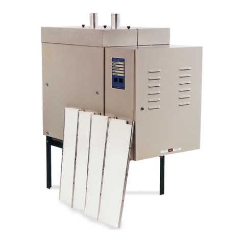
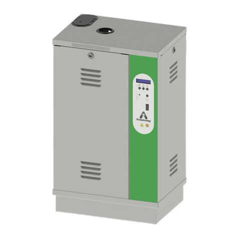
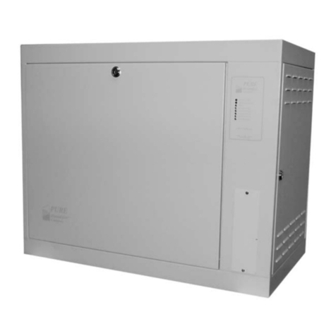
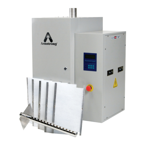
Armstrong HumidiClean HC-4100 Series Manual

Table!of!Contents
Page
Installation 2!-!9
Start-Up!Procedure!and!Operation 10!-!11
Maintenance 11!-!16
Troubleshooting 16!-!21
PC!Board!Switch!Data 22
Typical!Wiring!Schematic 23!-!24
Repair!Parts 25!-!31
Humidistat!Data 32!-!35
HumidiClean™
Series HC-4100/4145/4300/4500
Humidifiers
Installation, Operation and
Maintenance Instructions
Bulletin!537-G

2
Installation
Please read and save these instructions.
The Armstrong HumidiClean humidifier converts ordinary tap water or purified water to steam for
distribution to raise the relative humidity level.
To allow HumidiClean to function to its full capability, be certain to install in accordance with
Armstrong recommendations. Danger!
Electrical Shock Hazard High Voltages Exist Inside the Humidifier!
To protect yourself and others from accidental shocks:
1. Keep the humidifier locked during normal operation and store the key in a safe location
away from the humidifier.
2. Always disconnect the power supply at the circuit breaker or safety switch before
opening any covers or doors.
3. Before servicing the humidifier, learn where the high voltage parts are.The contactor
terminals and high voltage fuse blocks, along with the power module and heating
elements have shock potential. Keep hands and metal tools away from these areas
when power to the unit is on.
Pre-Installation
1. Check Shipment. A claim should be filed with the transportation company, (and
reported to Armstrong), if any items are missing or damaged.
2. Check Local Codes. The installation of HumidiClean should be in accordance with all
applicable building, plumbing, and electrical codes.
HC-4100 & HC-4300
(HC-4145 similar) HC-4500

3
3. Site Selection. The humidifier should be installed in an easily accessible location.
Do not install the unit where malfunction of the humidifier might cause damage
to non-repairable, unreplaceable or priceless property. Refer to Installation section
for other details regarding site selection.
Figure 3-1 HC-4100/4145/4300 Installation
Figure 3-2 HC-4500 Installation
Hose!Clamp
Soldered!Joints
UP
To!Drain
Hose
2"!Insulated!Copper
24
Clearance
Air!Gap
1"!ID!Hose
Fused!Disconnect
or!Magnetic!Breaker
Within!Sight!of!Unit
Water!In
3/8"!Copper!Type
with!Ball!Valve
1"!Copper!(Min.)!Pitched
1"!per!12"!(Min.)!to!Open!Drain
Pitch!Min.!1"!Per
12"!Back!to!Unit
See!Detail!"A"
Pitch!Min.!1"!per
12"!Back!to!Unit
"P"!Trap!Drain
Every!20'!of!Piping
or!at!Bottom!of!Vertical!Run
Full!Size!Tee
2"!Copper!Tee
Reducer
1/2"!or!3/8"
Copper!Tube
6"
Min.
Steam!Hose!or!Copper
Detail!"A"
Hose!Clamp Full!Size!Tee
See!Detail!"A"
Pitch!Min.!1"!per
12"!Back!to!Unit
"P"!Trap!Drain!Every
20'!of!Piping!or!at!Bottom
of!Vertical!Run
2"!Insulated!Copper
Fused!Disconnect
or!Magnetic!Breaker
within!sight!of!Unit
12"
Water!In
1/8!NPT
10"!Min.
3/4"!NPT!Pipe
Air!Gap
24"
1"!Copper!(Min.)!Pitched
1"!Per!12"!(Min.)!to!Open!Drain
Hose
1/2"!or!3/8"
Copper!Tube
Reducer
2"!Copper!Tee
Steam!Hose
Soldered!Joints
Up
To!Drain
Detail!"A"
6"!
Min.

4
HC-4100/4145/4300 Mounting
The HumidiClean models HC-4100/4145/4300 are designed to be wall mounted. A wall mounting
bracket and lag screws are provided for mounting on 16" (41 cm) centers. The operating weight of
the unit is 186 lb. (84 kg). A clearance of 24" (61 cm) on the right side and in front of the cabinet is
required for servicing.
1. Position wall mounting bracket level on wall and mark hole pattern. Make sure holes line up
with studs or other sturdy structure.
2. Use 3/8" x 1 1/2" lag screws provided to secure the bracket.
3. Hang the humidifier on the wall mounting bracket.The weight of the unit is 112 lb. (51 kg).
The HC-4500 HumidiClean is designed to be floor mounted on a level surface.The operating weight
is 370 lb., a clearance of 24" is required for the front and sides, 12" minimum for the back.
Water Fill Supply
The humidifier can use any potable or purified water supply.Water pressure must be
25-125 psi (1.7 - 8.6 bar). Water temperature must be less than 140°F (60°C).
1. Install a shut-off valve near the unit.
2. Connect the water supply to the 3/8" compression fitting on the fill water solenoid valve on
models HC-4100/4300, 1/8" NPT on HC-4500.The knock-out for the water supply tubing is to
the left of the fill valve in the side wall. (HC-4100/4145/4300)
Electrical Service Wiring
1. Connect main power supply wiring to high voltage terminals in unit. Read breaker size
required on humidifier’s nameplate and refer to Table 6-1 and 6-2 for HC-4100/4145/4300 wire
(gage) required;Table 6-1 and 6-3 for HC-4500. Make sure an interlocking circuit breaker or
safety switch (not furnished) is accessible and within sight of the unit.
2. The humidifier cabinet must be grounded.A ground lug is provided in the cabinet.
3. Use only wire with copper conductors rated 194°F (90°C) or higher for power supply
and grounding.

5
Table 5-1
Table 5-2
Table 5-3
Drainage
1. Connect HC-4100/4145/4300 drain to suitable waste drainage system. HC-4100/4145/4300
drain water may be as hot as 160°F (71°C) HC-4500 (212° F [100° C] ). Use clear drain hose
provided and 1" (2.5 cm) copper pipe pitched away from unit at 1" (2.5 cm) inch per foot. An air
gap to prevent back flow is required. See Figure 6-1.
2. Connect HC-4500 3/4" NPT fitting to a suitable waste drainage system. Note: drain water may be
as hot as 212°F (100°C) if this is unacceptable, Armstrong offers a condensate cooler (Temp-R-
Drain) which will temper the drain water to 140°F (60°C). See Figure 6-2. Use 1" (2.5cm) copper
pipe pitched away from the unit at 1" (2.5 cm) per foot. An air gap to prevent backflow is required.
A P-trap (10" minimum) is required for the tank overflow, use 3/4" copper pipe connected to the
3/4” NPT tank overflow connection.
Nominal Amp Rating 1-12 13-15 16-20 21-24 25-32 33-40 41-48 49-64 65-80 81-100 101-120 121-140 141-160
Wire
(
Ga
g
e
)
14 12 10 10 8 8 6 4 3 1 0 00 000
Circuit Breaker 15 20 25 30 40 50 60 80 100 125 150 175 200
Recommended Branch Circuts
Nom.
Amps
Three
Phase
Steam
Output
lb/hr
[kg/hr]
Nom.
Amps
Three
Phase
Steam
Output
lb/hr
[kg/hr]
Nom.
Amps
Three
Phase
Steam
Output
lb/hr
[kg/hr]
Nom.
Amps
Three
Phase
Steam
Output
lb/hr
[kg/hr]
Nom.
Amps
Three
Phase
Steam
Output
lb/hr
[kg/hr]
Nom.
Amps
Three
Phase
Steam
Output
lb/hr
[kg/hr]
Nom.
Amps
Three
Phase
Steam
Output
lb/hr
[kg/hr]
Nom.
Amps
Three
Phase
Steam
Output
lb/hr
[kg/hr]
208 84 90
[
41
]
— ————————— — — — —
208 — — — — — — 125 135 — — — — — — — —
240 — — — — 96 120
[
54
]
—————— — — — —
240 — — — — — — — — — — — — 144 180
[
82
]
——
380 — — 51 100
[
45
]
———————— — — — —
380 — — — — — — — — — — 77 150
[
68
]
————
380 — — — — — — — — 73 144
[
65
]
——— — — —
380 — — — — — — — — — — — — — — 110 216
[
98
]
480 — — — — — — — — 58 144
[
65
]
——— — — —
480 — — — — — — — — — — — — — — 87 216
[
98
]
600 — — — — — — — — 47 144
[
65
]
——— — — —
600 — — — — — — — — — — — — — — 70 216
[
98
]
72 kW Unit
HC-4500 / HC-4500 DI
Steam Capacities and Nominal Amperage Ratings
Volts
30 kW Unit 33.5 kW Unit 40 kW Unit 45 kW Unit 48 kW Unit 50.3 kW Unit 60 kW Unit
Steam!
Output
Steam!
Output
Nominal!
Amps
Steam!
Output
Nominal!
Amps
Steam!
Output
Nominal!
Amps
Steam!
Output
Single Three Single Three
208 13.3 7.7 8.3![3.8] 39 22 24![11] 37 40![18] 44 48![22] 74 80![36]
240 12.9 7.5 38 22 36 44 72
380 - 4.7 - 14 23 28 46
480 - 3.8 - 11 18 22 36
600 - 3 - 9 15 18 30
9.0![4.1]
Steam!Capacities!and!Nominal!Amperage!Ratings
Model!!HC-4100
!!!!!!!!!!!!!!!!!!!!!!!!!!!!!!!!!HC-4100!DI
Model!HC-4100!/!HC-4100!DI
!!!!!!!!!!!!!!!!!!!!!!!!!!!!!!!!HC-4145!/!HC-4145!DI
Model!HC-4300!/!HC-4300!DI
15!kW!Unit
18!kW!Unit
30!kW!Unit
27![12]
45![20]
54![25]
90![41]
Nominal!!!!!!!!
Amps
Voltage!
(Vac)
Phase
lbs![kg]!!!
hr
Phase
9!kW!Unit
Nominal!!!!!!!!
Amps
3!kW!Unit
lbs![kg]!!!!
hr
Three!
Phase
lbs![kg]!!!!
hr
lbs![kg]!!!
hr
Three!
Phase
lbs![kg]!!!!
hr
Three!
Phase

6
Duct Steam Distribution
1. The dispersion tube should be proper length .Verify correct size from Table 8-1.
2. Install dispersion tube(s) horizontally in duct so holes face upward. Air flow must be vertical up
or horizontal. Do not restrict duct with a height of 8" (20 cm) or less. Installations over 2000 FPM
(10 m/s) air velocity are not recommended. Consult factory if air flow is vertical down or air
velocity is over 2000 FPM (10 m/s). Do not install in ducted systems with static pressure
exceeding 6”WC (15 cm).
3. The dispersion tube(s) should be located upstream of a straight duct run, without obstructions,
10 feet (3 m) or more in length. Consult the factory if this distance is not available.
4. Use the template provided to cut dispersion tube installation holes.Fasten the mounting
plate to duct with sheet metal screws. If the dispersion tube is 36" (91 cm) or longer,
support the far end with threaded rod or similar means.
5. Note: For steam being generated from a deionized (DI) or reverse osmosis (RO) water source,
the use of 2” insulated stainless steel piping in lieu of copper is required. Contact the factory
with questions. Connect dispersion tube(s) to HumidiClean tank using 2" (5 cm) nominal insulated
copper pipe and hose cuffs provided.We do not suggest steam distribution piping of field supplied
rubber based compounds to be used for any HumidiClean application.Pitch pipe back to unit 1” (2.5
cm) per foot.The steam pipe must be free of kinks and sags to allow for gravity drainage of
condensate. Maximum pipe run distance from tank to dispersion tube is 40 feet (12 m) equivalent
piping length. Avoid excessive use of elbows or 45° changes in direction. A “P” trap drain should be
installed every 20 feet (6 m), of piping run or at the bottom of vertical runs that cannot drain back to
the tank. See Fig. 4-1 for “P” trap detail.
6. If duct static pressure plus piping back pressure is
greater than 6”WC, please consult the factory.
Figure 6-1 HC-4100/4300 Figure 6-2 HC-4500
Figure!6-3
Pressure!Loss!in!Copper!Pipe
(40!Foot!Equivalent!Run)
Figure!6-4
Do!not!pipe!this!drain!line
back!to!the!humidifier.
Air!Gap
"P"!Trap
10"!Min.
3/4"!NPT!Pipe
1"!Copper!(Min.)!Pitched!1"!per!12"!(Min.)!to!Open!Drain
Fitting!Style 1!1/4 1!1/2 2
45!Deg!Elbow 1.0 2.2 2.8
90!Deg!Elbow 2.5 4.3 5.5
90!Deg!Long!Elbow 1.5 2.7 3.5
Tee 5.0 9.0 12.0
Nominal!Pipe!Size
D
2
L
6" Min. Water Seal

7
Steam!Dispersion!Tube!Selection
Table 7-1
Area Steam Distribution
The EHF-3 fan package (minimum of 2 required for HC-4500) is designed to be hung on a wall to
operate as a remote mounted, direct area discharge option. It incorporates a blower rated at 120v-
2.90 amps. CFM rating is 465 @ 1530 RPM. The fan package requires a separate 120 volt power
supply (optional stepdown transformer available). Consult Armstrong Installation Bulletin IB-95 for
more information.
Alternative for shortened non-wettable vapor trail
For applications with particularly limited downstream absorption distance, Armstrong HumidiPack
may be considered. HumidiPack is a prefabricated separator/header and multiple dispersion tube
assembly. It provides uniform distribution and shortened non-wetting vapor trail. Consult
Armstrong Installation Bulletin No.560 for more information.
Control Wiring
Wiring for low voltage controls should not be run in same conduit as the power supply. Use of
shielded wire or a separate dedicated metal conduit is required. When shielded cable is used,
shield is to be grounded at the humidifier only. Refer to Figures 8-1 and 8-2 for wiring schematics.
Control Humidistat
1. Locate control humidistat where it will sense the average air condition of the space to be
humidified. Avoid areas of restricted circulation or locations where the sensor will be
subjected to drafts, localized heat or moisture sources.
2. Optional duct mounted humidistats are available to sense return or exhaust air, if preferred.
3. Set DIP switch S-3 in upper left portion of the PC board to proper range for the
humidistat control signal to be used. See Figure 9-1 and 22-1. Also set voltage source
jumper (J3) to proper range. See Fig. 9-1 for location of switches plus Figure 22-1
and applicable wiring diagram on Page 8 for correct switch setting.
4. Wire standard Armstrong 0-10 Vdc humidistat as shown in Figure 8-1. For use of
alternative humidistats, please refer to Figure 8-2.
Min. [cm] Max. [cm]
D-1 DL-1 12"
[
30
]
11"
[
28
]
16"
[
41
]
D-1.5 DL-1.5 18"
[
46
]
17"
[
43
]
22"
[
56
]
D-2 DL-2 24"
[
61
]
23"
[
58
]
34"
[
86
]
D-3 DL-3 36"
[
91
]
35"
[
89
]
46"
[
117
]
D-4 DL-4 48"
[
122
]
47"
[
119
]
58"
[
147
]
D-5 DL-5 60"
[
152
]
59"
[
150
]
70"
[
178
]
D-6 DL-6 72"
[
183
]
71"
[
180
]
82"
[
208
]
D-7 DL-7 84"
[
213
]
83"
[
211
]
94"
[
239
]
D-8 DL-8 96"
[
244
]
95"
[
241
]
106"
[
269
]
D-9 DL-9 108"
[
274
]
107"
[
272
]
118"
[
300
]
D-10 DL-10 120"
[
305
]
119"
[
302
]
130"
[
330
]
HC-4100,
HC-4100 DI,
HC-4145 and
HC-4145 DI Model
"D" Dia.
HC-4100,
HC-4100 DI,
HC-4145 and
HC-4145 DI Model
1-1/2" 2-3/8"
Duct Width
Steam
Dispersion
Tube Length
(L) [cm]
HC-4300,
HC-4300 DI,
HC-4500 and
HC-4500 DI Model
"D" Dia.
HC-4300,
HC-4300 DI,
HC-4500 and
HC-4500 DI Model

8
Figure 8-1
Standard Humidistat
H200-XX-XX-XX
5
27
28
Voltage!Source
Stat!In
Ground
Orange
Brown Part!No.
A8581
or
A8581A
On-Off!Humidistat
Switch!opens!on!RH!rise
Set S3 DIP Switch to 0 - 5 Vdc
SetVoltage Source (J3) Jumper to +5Vdc
5
27
28
Voltage!Source
Stat!In
Ground
White
Green
Black
Part!No.
C1471
or
C1472
Armstrong!Stat!C-1471!&!C-1472
1.9!-!3.9!Vdc
Set!S3!DIP!Switch!to!1.9!-!3.9!Vdc
Set!Voltage!Source!(J3)!Jumper!to!12!Vac
5
27
28
Voltage!Source
Stat!In
Ground
+
_
4 - 20 mA & 0 - 10Vdc Setting
See above for Armstrong 0 - 10 Vdc Humidistat
Connections
Set S3 DIP Switch to 0 - 10 Vdc or 4-20
mA (For use of standard Armstrong
Humidistat please see Fig. 9-1 note
regarding voltage source jumper)
Figure 8-2 Alternate Humidistats
ALL!SAFETY!SWITCHES!ARE!OPEN!ON!FAULT!TYPE.
SET!VOLTAGE!SOURCE!JUMPER!J3!TO!24!VAC.
SET!DIP!Switch!S3!TO!0-10!VDC
NOTE:

9
!!!!*Actual!switch!settings!may!vary.
See!Fig.!23-1!for!explanations!or
consult!factory.
High Limit Humidistat
Remove the jumper tab from terminals 24 & 25 and wire the high limit stat between these
terminals. Refer to Figure 8-1 (the overall wiring diagram) for more information. A duct mounted
high limit humidistat is recommended to prevent over-saturation of the duct air. Use an on-off
controller that opens on fault (high humidity). Humidistat should be set for a maximum of 90%
RH. Alternately, a modulating high limit humidistat may be used on applications such as variable
air volume (VAV). Locate the high limit humidistat approximately 10’ (3m) downstream of the
dispersion manifold. If 10’ (3m) is not available, consult the factory. Note: High limit humidistat
will be wired in series with duct pressure switch, if used, see Figure 8-1.
Airflow/Pressure Switch
An airflow switch is recommended to deactivate the humidifier when there is insufficient air flow
in a duct system. A duct pressure switch is preferred as an airflow sensor.The pressure switch
should open on insufficient airflow (opens on fault). Airflow switch should be mounted in supply
air duct upstream of humidifier dispersion. Remove the jumper tab between terminals 24 and 25
and wire the airflow sensor between these terminals.See Figure 8-1 (the overall wiring diagram)
for more information. Complete installation and wiring instructions are contained in the duct
pressure switch package.Note: Duct pressure switch will be wired in series with high limit
humidistat, if used, see Figure 8-1.
Alarm Circuit
The bottom 2 terminals on the TB2 connector on PC board, see PC Board drawing
Fig.9-1 on Page 9, are connections for a class II NEC alarm circuit (switch closure only,
1 amp.maximum @ 24 Vdc or 0.5 amp. @ 125 Vac). The switch will close when the error or service
LED’s are energized except when high humidity/sail switch circuit is open.
Actual!switch!setting!may!vary.
Please!see!page!8,!item!3.
Figure!9-1
PC!Board
Voltage!Source!Jumper
Please!see!Fig.!8-2!for
proper!setting.
J3
*

10
Start-Up Procedure
Before turning on the power:
1. Examine the electrical compartment for any loose or disconnected component wiring.
Check all high voltage screw terminal connections at contactor, terminal strip, fuse block
& power module for tightness.
2. Open side door (HC-4100, 4145, 4300).Remove tank access panel by unscrewing
two black knobs. Make sure all beds are fastened securely to mounting pins. Position access panel
on tank making sure the gasket is in place and tighten two black knobs
(seven on HC-4500).
Note: Ionic beds not used on DI/RO units.
3. Check and recheck incoming voltage source and control wiring for proper connections
and tightness of connections.
4. Turn on water supply and check for leaks.
5. Make sure access doors and panels are secure.
Principle of Operation
The HumidiClean humidifier converts ordinary tap water or purified water to steam for distribution to
raise the relative humidity level. The demand for humidity is sensed by a humidistat which sends a
control signal to HumidiClean.HumidiClean is connected to the power supply (either 208, 240, 380, 480
or 600 Vac) through a separate circuit breaker supplied by the customer. When power is initially
supplied to the unit from the circuit breaker, all LEDs will illuminate for 5 seconds.The “POWER” LED
will remain on and the unit’s fill valve solenoid is energized to allow water to enter the tank at a rate of
.31 gal/min (HC4500 fill rate is 2 gallons per minute).Note: If the water level in the tank is above the low
water level when power is applied, the drain valve will be energized to drain the water below the low
water level. Once the water level in the tank has reached the low water switch, assuming the air proving
switch is closed, the steam generator switch is on, and the high limit humidity switch is closed, the
heating elements will be activated and the “STEAM GENERATION” LED will be turned on.
The water fill solenoid continues to be activated until the water level in the tank has energized the high
water switch.Note: If fill or drain valves are not energized when power is first applied, check display
LEDs for diagnostic code.See DIAGNOSTICS section.The heating elements will remain on for 3
minutes to preheat the water inside the tank. During this preheat cycle the amperage draw of the tank
can be checked with a clamp on amp meter.The amperage draw on all high voltage wires connected to
the main power supply terminal block should correspond to the value on the nameplate.
After the 3 minute heat-up time, the HumidiClean will continue to produce steam based on the
demand signal from the humidistat. If the demand signal drops below 2% or the high limit/sail switch
circuit opens, the contactor(s) will open and the “STEAM GENERATION” LED will turn off. Note: If the
humidifier shut off due to low humidistat demand, a demand signal of 10% or greater is needed to re-
close the contactor and turn on the “STEAM GENERATION” LED. If all the signals are consistent as
stated above, HumidiClean will produce steam continuously and refill the tank with water when the low
water level is reached.These fill intervals will be started as defined in the software of the printed circuit.
Power to the heating elements is switched on and off by the triacs in the power module to
achieve a modulating output based on the signal demand from the humidistat.The triac utilizes a
1/2 second cycle time. For example, with a 50% humidistat demand signal the triacs would be on for
1/4 second and off for 1/4 second. If the triacs are fully on, the green “LOAD” LED on the power
module will be on constantly.When the triacs start to modulate (switch power to the heating
elements on and off) the LED will show the triac on condition and will appear to flicker or blink.
11
As HumidiClean continues to produce steam, the unit will accumulate and memorize the heating
element active time for the purpose of defining a drain cycle and service life (this memory is not affected
by power outages). When the HumidiClean heating elements have been on for the dip switch drain
frequency setting, the unit activates the drain and fill solenoids and begins draining the tank. The tank
will drain with the water being tempered (HC4100/4145/4300 only) from an activated water fill solenoid.
The drainage from the tank will pass the low water switch, opening the switch and shutting off power to
the heating elements. The drainage from the tank (HC-4100/4145/4300 only) should not exceed 160°F
(71°C) (HC-4500 212°F [100°C]).The drain cycle is controlled by the printed circuit board. The drain
cycle can be modified.See DIP Switch Settings Section. Once the unit has timed out of the drain cycle
and all of the switches are still in position to generate steam, the water fill solenoid switch is activated to
fill the tank and the cycle starts over again.
Completing a Service Life Cycle
When 90% of the selected service time has accumulated, the “Service Life” LED on the control
panel will begin to flash. (Refer to dip switch settings, for bed life duration settings). If the
HumidiClean is not serviced at this time, the unit will continue to operate for the remaining 10% of
the service life setting. When 100% of the bed life setting has been reached, the “Service Life”
LED will be on constant.The unit will drain the tank and not respond to a call for humidity.
A. Servicing the Unit
1) Record Current DIP Switch Settings
2) Accessing the Tank
a) Drain tank by flipping steam generation switch from “ON” to the “STEAM OFF &
TANK DRAIN” position.
b) Once the tank is drained, shut power off to unit and allow the tank to cool.
c) Open the cabinet access doors, and slowly open tank access panel.
3) Ionic Bed Inspection
Remove and inspect one of the ionic beds and inspect the drain screen at the bottom
of the tank. If it does not appear to be saturated with mineral deposit (a full bed will
weigh 2.5 pounds dry) and if the drain screen is clear, you have two options.
a) Reset the existing service life counter. In which case the unit will need to be
thoroughly checked at the next service life. To reset the service life: hold the
“RESET” button in (to the left) for 20 seconds until the front panel LED’s
illuminate than all go off (except the power LED). Proceed with Step 4.
b) Change the service life settings (see bed life adjustment procedure at the end
of this document).
4) Ionic Bed Replacement
If the beds are saturated (a full bed will weigh 2.5 pounds dry) remove all of them.
Remove any large pieces of scale from the tank. Scraping the tank is advised.
a) Chemically clean the unit with Rite-Qwik.
i) Pour one gallon of Rite-Qwik into tank followed by one gallon of fresh water.
The HC-4500 model requires 2 gallons of Rite-Qwik and 2 gallons of water.

12
ii) Allow the solution to work until the boiling action ceases.
iii) Clean the water level electrodes, using an emery cloth. See Page 15 for
complete instructions.
iv) Check water level canister for debris.
v) Replace the electrodes.
vi) Ensure drain lines are free of leaks and secure.
vii) Fill the tank with water and drain. (Perform this step several times.)
b) Install the new Ionic Beds.
5) Restoring the Unit to Operation
c) Put “STEAM GENERATION” switch on the “ON” position.
d) Turn power on at breaker, the LED’s will illuminate for 5 seconds, then go off
except for the “POWER ON” LED.
e) Unit should begin to fill. Fill time is approximately 23 minutes before “STEAM
GENERATION LED” will come on.
f) If this does not take place, reset the unit by holding the “RESET” button “ON”
(to the left) for 20 seconds until the front panel LED’s illuminate and than all
go off (except for the “POWER ON” LED).
B. Modifying the Bed Life Setting
1) Complete the steps for servicing the unit as outlined above.
2) The unit must run for at least one hour.
3) Power the unit down.
4) Set the dip switches to the desired EOL settings. See Page 22 for table of dip switch
settings.
5) Power the unit up. The new Bed Life Settings will be set.
Note: If the dip switches are reset prior to the completion of step two, the unit could
lock up. The power on LED will be lit, but the unit will not respond to any input. If this is
the case, the following steps must be taken to restore the unit to proper operation.
a) Power the unit down.
b) Reset the dip switches to the previous settings as recorded (Factory Defaults
are HC-4100 = 1000 hours, HC-4300 & HC-4500 = 500 hours).
c) Power the unit up at breaker.
d) Press and hold the “RESET” button to reset the EOL time. This must be held
for at least 20 seconds.

13
e) Allow the unit to run for at least one hour.
f) Power the unit down at breaker.
g) Set the dip switches to the desired settings. See Page 22 for the dip switch
settings.
h) Power the unit up at breaker.
End of Season Drain
If at any time during normal operation there is not a demand for a continuous 72 hour period,
HumidiClean drains the tank and the PC Board initiates a drying cycle by cycling the heating
elements for short intervals in order to dry the ionic beds.
Maintenance
The HumidiClean is designed to minimize maintenance.As stated in the PRINCIPLE OF
OPERATION section, after the HumidiClean has accumulated 90% of the selected Service Life, in
hours of heater on time, the “SERVICE LIFE” LED will flash (blink). At this time the ionic beds in the
tank should be replaced. If service is not performed, the unit will continue to operate for the
remaining hours before shutting down completely.
Note: Service Life can be adjusted based on water quality. If Ionic Beds are relatively free of scale
deposits or scale is forming on tank walls and elements because beds are saturated with scale,
Please consult the factory for Service Life adjustment procedures.

14
Replacing the Ionic Beds
1. Turn off steam generation switch and allow unit to completely drain.
2. Cut power at circuit breaker.
3. Unlock and open front and side doors (HC-4100/4145/4300).
4. (Caution: Tank will still be quite warm and should be allowed to cool.)
Unscrew two black knobs (6 knobs HC-4500) holding access panel and remove.
5. Unsnap ionic beds from support pins and slide them out through the access opening.
6. Inspect tank drain screen and elements inside the tank. The elements should appear
to be flaking off scale. If the drain screen appears to building deposits in the screen
holes it should be cleaned. Remove any flakes that appear in the bottom of the tank.
7. Install five (5) new ionic beds (14 for the HC-4500), snapping them into place on the support pins.
8. Be sure access panel gasket is lapped over all edges of tank access opening. Replace
and secure tank access panel.
9. Make sure both access doors/panels are secure.
HC-4500
HC-4100/4145/4300

15
10. Turn on power at circuit breaker.
11. Depress and hold in the reset button to the left for 20 seconds. All the LED’s will blink
together indicating the accumulated hours memory has been reset to zero. The unit should
now be heard filling.NOTE: The accumulated time memory can only be reset to zero when the
service LED is blinking or on solid.
12. The following step should be performed after the unit has started heating and is making steam.
Turn main power off and double check tank access panel gasket for steam leakage. Hand
tighten black knobs or reposition gasket if necessary.
Cleaning the Water Level Electrodes
1. If there is water in the steam generating tank, turn the Steam Generation switch to off. The
drain valve should energize, and the unit should completely drain.
2. After the tank has drained, turn off the main power at the disconnect.
3. Unclamp and remove the 5/8” ID Silicone tubing from the top outlet of the level canister.
4. Disconnect wires #20 (high level probe), #21 (low level probe) and #29 (common probe)
from the probes, noting the probe and wire locations. Note: Level control float switches are
used for DI, RO, or very pure water. Cleaning should not typically be required.
5. Unscrew the probes from the level canister using the hex nut fitting on the probe
(Note: Level canister bushings may be removed with the probes, if necessary).
6. Use a wire brush, wire wheel, or similar means to clean scale deposits off the stainless
steel tip of the probe. Cleaning of the teflon insulating jacket (white portion) should not
be needed.
7. Wipe probes with a clean dry cloth.
8. Inspect the interior of the level canister. If large amounts of scale or debris are present,
remove the canister from the cabinet by removing the two clamping bracket screws and
disconnecting the 5/8” ID Silicone hose at the bottom of the canister. Flush the canister with
water to remove debris and reinstall.
9. Reinstall the probes and probe wires in their proper locations. The high water probe(shortest)
goes in the right hole of the canister. The low water probe (medium length) goes in the left
front hole of the canister. The common probe (longest) goes in the left, rear hole of the
canister.
10. Reconnect the 5/8” ID Silicone hose(s).

16
Removing The Tank HC-4100/4145/4300 Only
1. Turn steam generation switch to off and allow unit to complete a deep drain.
(Caution: Tank will still be quite warm).
2. Turn off circuit breaker.
3. Unlock and open front and side doors.
4. Disconnect 3 hoses from front of tank; rubber hose cuff at steam outlet; heating element
leads at contactor, fuses, or power module; and thermocouple wires.
5. Loosen 3 mounting bolts on left side of tank, do not remove. Remove the three
mounting bolts on the right side of the tank. Slide tank out right side of cabinet
(be sure tank had time to cool after operation).
Troubleshooting
Notice: This troubleshooting guide is offered to aid in servicing the HC-4000 humidifiers.It is intended
for use by electricians and technical service personnel familiar with electrical and electronic equipment.
Many steps in the troubleshooting procedures require measurements of high voltages and involve
working near exposed live parts.KNOW WHERE THE HIGH VOLTAGE PARTS ARE, AND KEEP
HANDS AND METAL TOOLS AWAY FROM THEM. If unsure concerning any of the following
procedures, PLEASE consult the factory, Armstrong Humidification Department at (269) 273-1415. All
resistance checks should be made with main power OFF and the component disconnected from wiring.
All continuity checks should be made with main power OFF.
Humidifier will not fill with water when power is applied.
1. Make sure Steam Generation Switch is on and verify continuity at terminal block TB1 on
display circuit board (between center common and right most terminals).
2. Make sure “SERVICE LIFE” and/or “ERROR” LEDs are not on. If so, refer to
MAINTENANCE or DIAGNOSTICS section of this manual.
3. Make sure “POWER” LED is lit. If not, check voltage at secondary side of the main
power transformer.Voltage should be 24-28 VAC. No or low voltage is an indication of a
problem with the supply voltage or transformer.Verify supply voltage and make sure it
is the same as voltage rating on humidifier nameplate. Check secondary power fuses.
4. Check the voltage to the fill valve.Voltage should be 24-28VAC.If voltage is present,
fill valve solenoid coil is probably defective. Coil resistance should be 18Ω
(8.8ΩHC-4500) with wires disconnected.
5. Check for water in cabinet bottom or in fill cup overflow line. If present, see “Water in
bottom of cabinet” on page 20 (HC-4100/4145/4300 only).
6. If no voltage to fill valve, check water level.If it is above 1/3 full in electrode level
canister (float canister for DI units), the drain valve has to open to drain water below low
water level before the fill valve is energized.
7. Check for 24-28 Vac power to drain valve. If power to drain valve is OK, check drain
valve coil resistance with wires disconnected. It should be approximately 10 Ω(4.1Ω
HC-4500).

17
8. If drain valve and fill valve are both energized and water is below the 1/3 full level in the
electrode canister (float canister for DI units), make sure Steam Generation Switch is
ON. Perform continuity check to be sure.
9. If drain valve only is energized and water level is below the 1/3 full level in electrode
canister (float canister for DI units), there may be excessive debris in electrode canister
(float canister for DI units).Inspect and clean if needed. See page 15 for Cleaning
Procedure for Electrodes.
10.PC board may be defective. Consult the factory.
Humidifier fills with water, but does not turn “STEAM GENERATION” LED on for
3 minutes after reaching low water level.
1. Perform steps 1 through 3 from above “Humidifier will not fill...”
2a. For Tap Water: Check AC voltage across the ground electrode (longest) and the low level
electrode (medium length).The voltage will be approximately 17-20 VAC if the circuit is open.When
the water level closes the circuit the voltage should drop to <5 volts.
(a)If voltage is not 17-20 VAC with circuit open, check continuity of wires from
electrodes to PC board. If continuity is OK, the PC board is likely defective.
(b) If voltage is 17-20 VAC with circuit open, but does not drop when water contacts
the two electrodes, the water may be too pure (consult factory) or if the voltage
drops very slowly to about 5 volts then the electrodes need cleaning. See page 15
for cleaning procedure for electrodes.
2b. For DI Water: Check continuity across the two wires to the low water float switch. If no
continuity, switch may be defective or “hung up”. Make sure axis of switch is vertical so the float
arm swings freely.
3. If high limit/sail circuit is closed, low water level circuit is closed, and humidistat is
calling for humidity, the “STEAM GENERATION” LED should be illuminated. If “STEAM
GENERATION” LED is not lit, PC board or wiring harness is defective.
“STEAM GENERATION” LED turns on after initial fill to low water level, but amperage
draw checkshows low or no amperage draw.
1. Check for line voltage to heating elements at secondary side of contactor and/or power
module.Verify power supply is same as voltage rating on humidifier nameplate.
2. If voltage is correct, the heating elements are likely defective.Turn off main power,
disconnect all elements and check element resistances (see resistance chart on
Page 26 and 28). Look for open circuits or elements with high resistance.
3. If voltage is not present at elements, check primary voltage fusing.
4. If fuses are OK, check voltage to contactor coil.
(a) If voltage is 24-28VAC at contactor coil, check coil resistance.It should be 8W with
wires disconnected.If resistance is OK, check voltage drops across the contactor.

18
(b) If no voltage to contactor coil, check continuity of wires from PC board to contactor.
If continuity is OK, PC board is likely defective.
5. Check voltage signal to power module.The voltage across EC1-10 and EC1-18 (low
voltage signal to power module) should be 11-12 Vdc.
(a) If no or low voltage, the PC board is likely defective.
(b) If voltage is OK, but green “LOAD” LED on the power module is not on, power
module is defective.
6. If green “LOAD” LED on power module is on, check voltage drops across power module.
Humidifier overfills with water on initial fill.
1. Check electrode canister (float canister for DI units) and level electrodes for debris or scale build up.
Clean as needed. See Page 16 for cleaning procedure for electrodes. On DI Units, the high water
float switch may be defective or “hung up”. Check continuity across wires to the switch. Make sure
switch axis is vertical so float lever arm swings freely.
2. The fill valve may be stuck open.Turn off power to the humidifier. If fill valve does not
close, clean or replace valve.
3. If the high water circuit is closed and the fill valve shuts off when the power is turned off,
the PC board is defective.
Humidifier runs continuously, %RH is well over set-point.
1. Verify humidistat is wired correctly and stat selector jumpers (S3 & J3, See Fig. 9-1
and 22-1) on the PC board are set correctly for the humidistat signal.
2. Disconnect humidistat wiring to humidifier. If humidifier shuts off, the problem is with the
humidistat. Consult humidistat manufacturer or Armstrong for proper troubleshooting/
calibration procedures.
3. If humidifier generates steam with the humidistat disconnected.
(a) Check for power at the contactor coil. If 24-28 VAC, PC board is defective.
(b) Check voltage drop across contactor. If voltage drop is low (it should be line
voltage), remove, disassemble and inspect contactor.
(c) Check green “LOAD” LED on power module. If it is On or blinking, PC board is
likely defective.
(d) Check voltage drop across power module.If voltage drop is low (it should be line
voltage), power module triacs may be failed closed. Shut off main power and
perform continuity check across high voltage input and output terminals. Continuity
indicates a shorted triac. Note: Some power modules have two triacs rather than
three. Check schematic on power module to verify.
Humidifier runs continuously, %RH is well under set-point.
1. Verify humidistat is wired correctly and stat selector jumpers (S3 & J3, See Fig. 9-1
and 22-1) on the PC board are set correctly for the humidistat signal.

19
2. Check humidistat demand signal at low voltage terminal strip. It should be close or at 100%.
3. If humidifier is a three phase model, verify all three phases of power are present and equal.
4. Check amperage draw on all high voltage power lines with a clamp on amp meter.They
should be same or very close to amperage rating on the humidifier’s nameplate if the
humidistat demand is 100%.
5. Turn off power. Disconnect heating elements and check resistances – see Table on
Pages 26 and 28. If an open circuit or abnormally high resistance is measured, the heating
element(s) is defective. Also, check to see if heating element leads have shorted to ground.
6. If heating elements are OK, check voltages at secondary side of the power module and
contactor. If no or low voltage, check primary fusing.
7. If fuses are OK, check voltage to contactor coil.
(a)If voltage is 24-28VAC at contactor coil, check coil resistance. It should be
approximately 8Ωwith wires disconnected. If resistance is OK, check voltage
drops across the contactor.
(b)If no voltage to contactor coil, check continuity of wires from PC board to contactor.
If continuity is OK, PC board is likely defective.
8. Check voltage signal to power module.The voltage across EC1-10 and EC1-18 (low
voltage signal to power module) should be 11-12 Vdc at 100% power.
(a)If no or low voltage, the PC board is likely defective.
(b)If voltage is OK, but green “LOAD” LED on the power module is not on, power
module is defective.
9. If green “LOAD” LED on power module is on, check voltage drops across power module.
10.If supply voltage and amperage draws are correct and elements appear OK, unit is
probably undersized (not enough capacity for the application).Check sizing or consult
factory.
Humidifier does not drain when Steam Generation is switched OFF.
1. Disconnect and check resistance of drain valve coil.Resistance should be
approximately 10Ω(4.1ΩHC-4500).
2. Make sure drain line is pitched and sized correctly. Check for blockage or obstructions
in the drain line. An air gap or funnel may be needed – See Figures 6-1 and 6-2.
3. If humidifier does not drain at specified interval or when service is to be performed and
drain valve and piping appear OK, there is blockage of the tank drain screen or the PC
board may be defective.
Dispersion tube spits water or water is present in duct
Hint: It is very helpful to cut a small observation window in the duct and cover it with plexiglass so the
steam discharge from the manifold can be observed.This way the problem can be narrowed down to
piping/steam quality (steps 1 and 2) or a condensation problem (steps 3 and 4).

20
1. Check distribution piping for proper pitch and size.Make sure there are no loops, dips or
sags where pockets of water can collect.If such conditions exist and are unavoidable, a‘P’
trap is needed to drain the low spots.
2. Make sure any drains are piped correctly and pitched to a floor drain.
3. Check duct downstream of manifold.If any obstructions (coils, elbows, fans) are within 10',
the vapor (condensed steam) discharged from the manifold may be impinging on the obstacle before
it has a chance to adsorb into air.This is especially true if the duct air is cold (<60°F), duct air velocity
is high (>1000 FPM), or duct %RH is high (>90%).If these conditions exist and impingement is
suspected, consult factory.
4. The duct air may be saturated with moisture (100% RH). A high limit humidistat is
recommended to prevent this.See Installation section.
Water in bottom of cabinet HC-4100/4145/4300 Only
1. Verify that pressure equalizing tubing is hooked up from top of electrode level canister
to the tank.
2. Check steam distribution piping for obstructions.
3. Verify duct air velocity is less than 2000 FPM and manifold is not in a vertical down air flow.
4. Check for leaks at fittings and clamps in water supply lines.
5. Verify that tank access panel gasket is on lip of access hole and the access panel is
secured tightly.
6. Make sure the duct pressure and steam distribution back pressure don’t total more than
6”WC.
Diagnostics
There are some diagnostic routines programmed into the PC board.If these routines detect a problem
the unit will shut down and flash the “ERROR” LED a certain number of times, followed by a long pause.
1 Blink - - The low level switch has not closed after 35 minutes of fill valve on time.
This is only on initial start-up or after a complete drain down.
Check: defective fill valve, debris in fill valve inlet screen or on tank drain screen,
water leakage from tank or inlet tubing, no water flow or low water pressure, drain valve
stuck open or leaking, defective low water level switch (electrodes need to be cleaned).
2 Blinks - - The low level switch has not closed after 3 minutes (7 minutes HC-4500) of fill
valve on time.This is only after initial start-up fill and boil-down sequence.
Check: debris in water switch canister, defective fill valve, no water flow or low water
pressure, drain valve stuck open, defective low water level switch (electrodes need to be
cleaned).
3 Blinks - - The high level switch has not closed after 56 minutes of fill on time.
This is only on initial start-up or after a complete drain down.
Check: debris in fill valve inlet screen or in tank drain screen, water leaking from tank
or inlet tubing, low water pressure, defective high water level switch (electrodes need to
be cleaned).
4 Blinks - - The high water switch is still closed 5 minutes after the fill valve has turned off
upon hitting the high water level and a 30 second drain does not drop the water below
the high water level.
Check: defective high water level switch, debris in level canister, fill valve stuck open,
drain valve is defective or scale buildup in drain line.
This manual suits for next models
3
Table of contents
Other Armstrong Humidifier manuals

Armstrong
Armstrong Series HC- 6100 Manual

Armstrong
Armstrong C-1801 User manual

Armstrong
Armstrong HumidiClean HC-6000 Series Manual

Armstrong
Armstrong ElectroVap ERS-LC User manual

Armstrong
Armstrong EHU-600 Instruction Manual

Armstrong
Armstrong ERS-LC Series User manual

Armstrong
Armstrong EM-1000 Series Owner's manual

Armstrong
Armstrong 6100 Manual

Armstrong
Armstrong AM-91A Owner's manual

Armstrong
Armstrong HumidiClean HC-6700 Series Manual