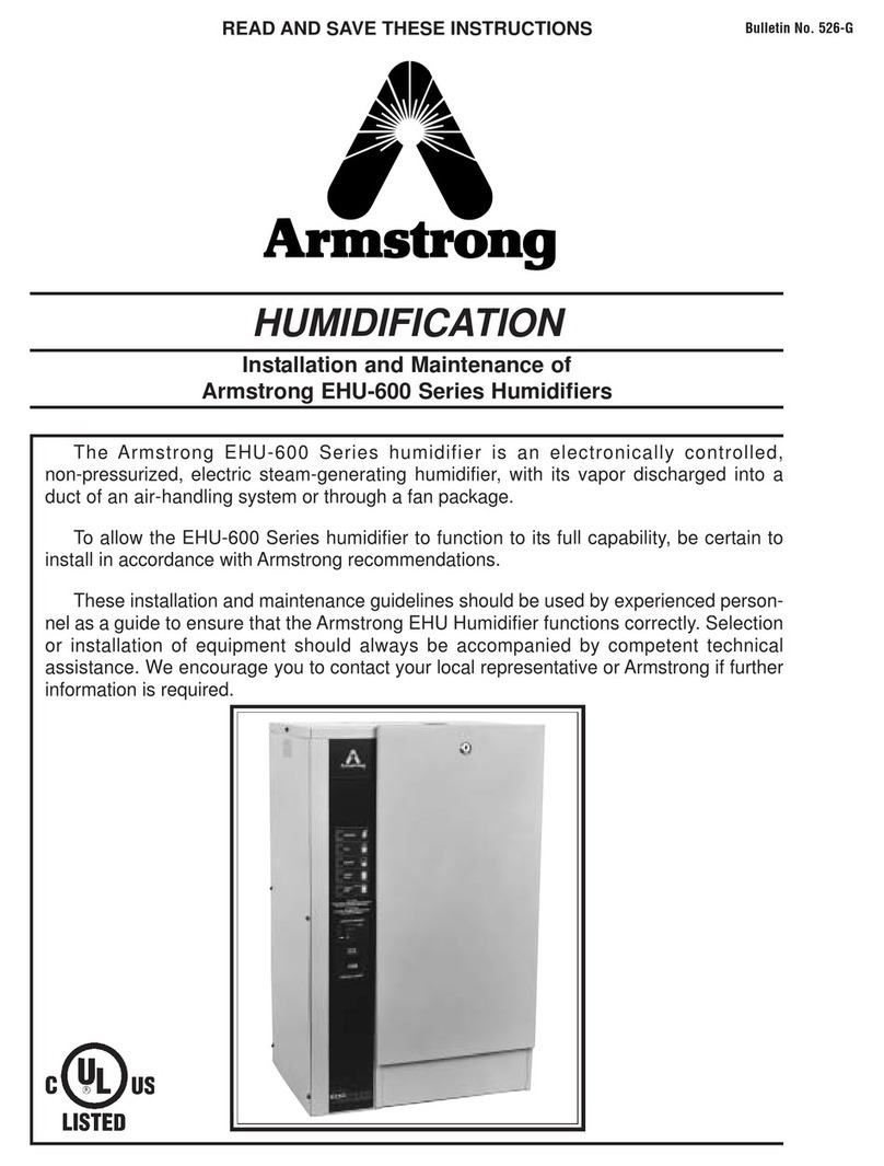
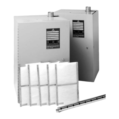
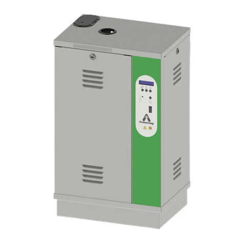
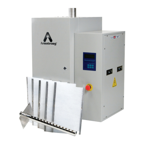
Armstrong ERS-LC Series User manual

Electric Resistive Steam Humidifier
ERS-LC Series,
Instructions, Operations, and
Maintenance Manual
The installation and service must be performed by a qualified installer.For
further information, please call our technical department at 269-273-1415

2
Designs, materials, weights and performance ratings are approximate and subject to change without notice. Visit armstronginternational.com for up-to-date information.
Armstrong International
North America • Latin America • India • Europe / Middle East / Africa • China • Pacific Rim
armstronginternational.com
This bulletin should be used by experienced personnel as a guide to the installation of the Armstrong ERS-LC.Selection
or installation of equipment should always be accompanied by competent technical assistance. You are encouraged to
contact Armstrong International, Inc. for additional information.
1. General Safety Information
Icon Legend
WARNING! Injury or death and property damage are possible.
CAUTION! Potential property damage, expensive repairs,voiding the equipment
warranty may result.
BURN HAZARD! Contact with steam, hot water, or hot metal surfaces can cause severe skin
burns. Skin exposure to 140°F (60°C) water or metal for only five (5)
seconds may cause a second degree burn.
Failure to comply with instructions following a safety icon may result in adverse consequences including property
damage, personal injury, or, in extreme cases, death.
General Safety Guidelines:
1. Inappropriate use (beyond typical, intended use) could cause damage to the product and other property. It may also
resultin personal injury or, in extreme cases, death.
2. Only designated, qualified, and competent personnel should operate, maintain, and service this equipment in
accordance with the directions in this product instruction manual.
3. Improper setup, operation, or maintenance may void the product warranty.
4. When operating and maintaining this product:
a. ALWAYS select and wear appropriate personal protective equipment (PPE) before carrying out any physical work
at the job site, per site-specific requirements. Appropriate PPE may include hard hats, safety glasses, gloves, boots or
shoesw/ non-slip soles and toe guards, and protective overalls.
b. ALWAYS scan the work area and take note of potential hazards before entering. Adjust your travel path or work
positionto avoid hazards and personal injury.
c. ALWAYS observe designated safety procedures when working in hazardous locations (areas containing explosive
and combustible gases, vapors, and dusts) and confined spaces (locations where the breathable air supply is limited
or variable, or where entrapment could occur).
d. ALWAYS use proper lockout-tagout procedures to disconnect power sources and de-energize machinery before
conducting installation, service, and repair.
e. ALWAYS use great care and appropriate safety gear when working above ground level, especially on ladders and
platforms or in the presence of overhead, electrical power lines.
f. ALWAYS shut off all “live” steam, water supply, and condensate return lines before breaking or loosening any
plumbing joints.
g. ALWAYS carefully relieve any residual internal pressure in the system or connecting pipe work before breaking or
loosening any plumbing joints.
h. ALWAYS allow hot parts to cool before servicing to avoid the risk of skin burns.
!
!
1.1 INTRODUCTION

3
Designs, materials, weights and performance ratings are approximate and subject to change without notice. Visit armstronginternational.com for up-to-date information.
Armstrong International
North America • Latin America • India • Europe / Middle East / Africa • China • Pacific Rim
armstronginternational.com
1.2 IMPORTANT REMARKS
GENERAL
Maintenance, service, repairs, as well as the study of the risks and dangers
associated with these operations must be carried out by qualified, competent, and
authorized personnel.
- Make sure that all risks or dangers are defined beforehand by an authorized person,
especially at elevated heights.
- We also recommend installing a security perimeter.
- Make sure that the power supply is switched off before performing maintenance.
- Please periodically tighten all the connection terminals of the power cable.
INTENDED USE
This device manufactured by Armstrong is intended solely for humidification purposes,
discharged into the duct of an air-handling system or through a fan package. The user
undertakes to use it according to the safety instructions given in this manual.
Improper use could result in serious hazards and damages to the user, third parties,
and materials.
STORAGE &
MAINTENANCE
The device must be stored in a dry, frost-free place, protected from shocks and
vibrations. Handling must be carried out by at least two people or suitable lifting
equipment.
WATER
Steam humidifiers can be used with potable, demineralized, or softened water. It is
absolutely forbidden to inject a chemical into the hydraulic system. Make sure that
the water supply pressure does not exceed 87 psi (5.9 bar). Always be careful that the
installation meets all state and local building codes.
ELECTRICITY
The user ensures that electrical installation will be carried out by an authorized
technician in this field. The installer must provide the correct cable section as well as
the thermal-magnetic circuit breaker protection, adapted to the regulations in place in
the country of installation.
WARRANTY
Armstrong International, Inc. (“Armstrong”) warrants to the original user of those
products supplied by it and used in the service and in the manner for which they are
intended, that such products shall be free from defects in material and workmanship
for a period of one (1) year from the date of installation, but not longer than 15
months from the date of shipment from the factory, [unless a Special Warranty Period
applies, as listed below]. This warranty does not extend to any product that has been
subject to misuse, neglect or alteration after shipment from the Armstrong factory.
Except as may be expressly provided in a written agreement between Armstrong
and the user, which is signed by both parties, Armstrong DOES NOT MAKE ANY
OTHER REPRESENTATIONS OR WARRANTIES, EXPRESS OR IMPLIED, INCLUDING,
BUT NOT LIMITED TO, ANY IMPLIED WARRANTY OF MERCHANTABILITY OR ANY
IMPLIED WARRANTY OF FITNESS FOR A PARTICULAR PURPOSE.
LIABILITY
IN NO EVENT SHALL ARMSTRONG BE LIABLE FOR SPECIAL, DIRECT, INDIRECT,
INCIDENTAL OR CONSEQUENTIAL DAMAGES, INCLUDING, BUT NOT LIMITED TO,
LOSS OF USE OR PROFITS OR INTERRUPTION OF BUSINESS. The Limited Warranty
and Remedy terms herein apply notwithstanding any contrary terms in any purchase
order or form submitted or issued by any user, purchaser, or third party and all such
contrary terms shall be deemed rejected by Armstrong.

4
Designs, materials, weights and performance ratings are approximate and subject to change without notice. Visit armstronginternational.com for up-to-date information.
Armstrong International
North America • Latin America • India • Europe / Middle East / Africa • China • Pacific Rim
armstronginternational.com
1.0 PRODUCT PRESENTATION 5
1.1 CHARACTERISTICS 5
1.2 SIZE 6
1.3 HUMIDIFIER COMPONENT PARTS 7
1.4 IMPORTANT INSTRUCTIONS 8
2.0 INSTALLATION 9
2.1 PROCEDURE 9
2.2 WATER SUPPLY 10
2.3 DISPERSION TUBE POSITIONING 11
2.4 STEAM OUTLET 16
2.5 DRAIN HOSE CONNECTION 17
2.6 ELECTRICAL CONNECTIONS 19
2.7 ELECTRICAL WIRING 21
2.8 CONTROL SIGNAL CONNECTION 23
2.9 WIRING DIAGRAMS 29
2.10 HEATING ELEMENTS WIRING DIAGRAMS 31
2.11 WATER LEVEL DETECTOR WIRING 33
2.12 OPTION: TRANSFORMER CONNECTION 34
3.0 COMMISSIONING 35
4.0 SYSTEM MANAGEMENT 36
4.1 MENU INFORMATION (READ ONLY) 36
4.2 SETUP MENU 38
4.3 CONTROL SYSTEM MENU 39
4.4 CHANGE SETTINGS MENU 41
4.5 MAINTENANCE ALERTS 44
4.6 ERROR MESSAGE 45
5.0 MAINTENANCE 51
5.1 STAINLESS STEEL TANK 51
5.2 DRAIN VALVE 52
5.3 WATER INLET VALVE 53
5.4 WATER LEVEL SENSOR 53
6.0 SPARE PARTS 54
6.1 STAINLESS TANK 54
6.2 WATER INLET VALVE 55
6.3 WATER LEVEL DETECTOR 55
6.4 DRAINING CIRCUIT 55
6.5 ELECTRICAL PART 56
Contents

5
Designs, materials, weights and performance ratings are approximate and subject to change without notice. Visit armstronginternational.com for up-to-date information.
Armstrong International
North America • Latin America • India • Europe / Middle East / Africa • China • Pacific Rim
armstronginternational.com
1.0 PRODUCT PRESENTATION
1.1 CHARACTERISTICS
The ERS-LC humidifier is an electric humidifier, designed for air humidification in an air handling unit. Like all the other
humidifiers of this range, it’s compatible with the EHF Fan Pack.
Standard delivery includes:
1. Steam humidifier
2. Technical documentation
3. (3) hose clamps: (2) for the steam hose and (1) for the drain hose.
Fig. 1-1: Humidifier
ACCESSORIES (Not supplied)
• Stainless steel steam dispersion tubes • Filling cup extension
• ExpressPack® • Additional cooling kit
• Blower Pack fan unit • Mounting bracket
• Steam and condensate hose
• Duct or room humidity sensor
• High Limit Humidistat
• Drain hose
• Stainless steel braided hose in 3/4" FF
(with gaskets) for connection to water network.

6
Designs, materials, weights and performance ratings are approximate and subject to change without notice. Visit armstronginternational.com for up-to-date information.
Armstrong International
North America • Latin America • India • Europe / Middle East / Africa • China • Pacific Rim
armstronginternational.com
1.2 SIZE
Fig. 1-2: Humidifier sizes
Model name ERS-LC 3-30
Number of steam outlet 1
Dimension [mm] / [in]
A: Total width 554 / 21.81
B: Total height 750 / 29.53
C: Depth 285 / 11.22
D: Height 678 / 26.70
E1: Steam outlet position 417 / 16.42
E2: Steam outlet position 137 / 5.39
G1: Drain water position 417 / 16.42
G2: Drain water position 137 / 5.39
H1: Water inlet position 222 / 8.74
H2: Water inlet position 181 / 7.13
I: Condensate outlet diameter Ø 25
K: Steam outlet diameter Ø 40
Weight [kg] / [lb]
Weight in operation 35 / 77.16
Gross weight (packed) 25 / 55.12

7
Designs, materials, weights and performance ratings are approximate and subject to change without notice. Visit armstronginternational.com for up-to-date information.
Armstrong International
North America • Latin America • India • Europe / Middle East / Africa • China • Pacific Rim
armstronginternational.com
Fig. 1-3: Humidifier component parts
1 Steam hose
2 Filling cup
3 Display board
4 Main board
5 Contactor
6 Fuse holders
7 3 relay board (optional)
8a Transformer 2x115 / 2x12V S: 50VA
8b Transformer for UL Standards
9 ON/ OFF Switch
10 Power rail
11 Identification label
12 Inlet valve
13 Funnel
14 Overflow hose
15 Drain valve
16 Filling hose
17 Tank
18 Water level sensor
19 Heater
20 Water level hose
21 Static relay
22 Fan
1.3 HUMIDIFIER COMPONENT PARTS

8
Designs, materials, weights and performance ratings are approximate and subject to change without notice. Visit armstronginternational.com for up-to-date information.
Armstrong International
North America • Latin America • India • Europe / Middle East / Africa • China • Pacific Rim
armstronginternational.com
1.4 IMPORTANT INSTRUCTIONS
• Ambient temperature: between 41°F(5°C) and 104°F(40°C)
• Ambient humidity: < 80% Relative humidity
• Back side: this component heats during operation {up to 140°F(60°C)}. Make sure that the support of the device is not
made of a heat sensitive material.
• Wall mounting: Please be careful that the support material receiving the device (pillar, wall, etc.) can hold it.
• Weight in operation 77 lbs. Gross dry weight 55 lbs.
• Fixation: use a fastening system adapted to the support material.
• Make sure that the following mounting distances are met .
Fig.1-4: Mounting distances
Standard Measurements
Please read and follow the enclosed safety information and the warning labels inside the humidifier
before installation or maintenance.
Some steps can be dangerous.
Visit our website or contact our operators for technical support.
Milimeter Inch
1250 49.21
50 1.97
200 7.87
500 19.69
1000 39.37

9
Designs, materials, weights and performance ratings are approximate and subject to change without notice. Visit armstronginternational.com for up-to-date information.
Armstrong International
North America • Latin America • India • Europe / Middle East / Africa • China • Pacific Rim
armstronginternational.com
2.0 INSTALLATION
2.1 PROCEDURE
• Mark and drill where indicated (holes size depends on the selected wall anchors and support materials).
• Put the dowels in the holes.
• Screw the top screws into the dowels (M6 recommended), let them protrude by about 0.39 in / 10 mm.
• Hang the device to the top screws and align it vertically and horizontally ensure device is level.
• Tighten up all screws.
Fig. 2-1: Installation holes
A: 450 / 17.71
A1: 35 / 1.38
A2: 53 / 2.09
B: 510 / 20.08
B1: 81 / 3.19
C 7 / 0.28
ERS-LC
[mm] / [in]

10
Designs, materials, weights and performance ratings are approximate and subject to change without notice. Visit armstronginternational.com for up-to-date information.
Armstrong International
North America • Latin America • India • Europe / Middle East / Africa • China • Pacific Rim
armstronginternational.com
2.2 WATER SUPPLY
2.2.1 Recommendation
Tap water (according to Directive 98/83EEC),softened
water, use possible under conditions.Please contact
our services. A visual internal tank inspection is
highly recommend after 250 hrs. of total run time
when tap water is used.
Demineralized water, reverse osmosis water
Flexible braided hose with
3/4” FF thread
Isolation valve
Water supply
Fig. 2-2: Humidifier water supply
Softened water: Its use is not recommended, but possible.
Water analysis is recommended to determine the level of sodium chloride.
Do not hesitate to contact our services for support.
2.2.2 Recommendations on connection
Network water pressure: The pressure must be stable and between 29 psi(2 bar) and 87psi (6 bar) MAX.
Network water temperature: < 104°F (40°C).
Please note that the water supply is connected at the lower part of the unit.
For easy maintenance, the water inlet valve is equipped with a filter strainer which should be checked periodically.
It is essential to install an isolation valve near the humidifier in order to facilitate maintenance.
The demineralized water is corrosive; use appropriate piping material: stainless steel, PVC.
An excess of sodium chloride may generate foam which disturbs the correct running of the humidifier.
It is essential to install a duplex softener.
Max. chloride content: 80 mg/L
OVERFLOW RISKS: It is recommended to install a collecting water tank under the humidifiers to
prevent overflow. This is essential if the unit is installed in false ceilings or above important rooms
(example: museum room, showroom, laboratory, etc.). Make sure the container is connected to the
wastewater system.
Our device is designed to be used with any following water type:

11
Designs, materials, weights and performance ratings are approximate and subject to change without notice. Visit armstronginternational.com for up-to-date information.
Armstrong International
North America • Latin America • India • Europe / Middle East / Africa • China • Pacific Rim
armstronginternational.com
2.3 DISPERSION TUBE POSITIONING
Steam dispersion tubes:
The steam from the humidifier is injected in a duct or an air handling unit via a steam dispersion tube.
In order to obtain the best performance of the humidifier, select the longest pipe .
Spirit level
Threaded rod
Fig. A 2-3: Steam dispersion tubes positioning
Fig. B 2-3: Hole dimension to be cut in the duct

12
Designs, materials, weights and performance ratings are approximate and subject to change without notice. Visit armstronginternational.com for up-to-date information.
Armstrong International
North America • Latin America • India • Europe / Middle East / Africa • China • Pacific Rim
armstronginternational.com
2.3.1 Absorption distance "D"
Make sure that the absorption distance is met in order to let the air absorb the steam dispersed by the tubes.
In this absorption distance, the steam is still visible in the air stream in the form of fog. If any obstruction is
placed in this area, condensate may occur. For this reason, it is imperative to consider this absorption distance
when placing the humidifiers.
2.3.2 How to calculate absorption distance « D »
In order to determine the absorption distance, the attached calculation table can be used:
• RH1 = relative humidity of air before humidification in %.
• RH2 = relative humidity of air after humidification in %.
• D mini = minimum absorption distance in feet (ft).
Inlet RH1 [%]
5 10 20 30 40 50 60 70
Minimum absorption distance “D” [ft]
2.95 2.62 2.30 1.64 - - - -
3.61 3.28 2.95 2.62 1.64 - - -
4.59 4.27 3.94 3.28 2.62 1.64 - -
5.91 5.58 4.92 4.59 3.94 3.28 2.30 -
7.55 7.22 6.89 6.23 5.58 4.92 3.94 2.62
11.48 11.15 10.50 9.51 8.86 7.87 6.89 5.58
Outlet RH2
[%]
40
50
60
70
80
90
This calculation table is to be used for temperatures between 68°F (20°C) and 77°F (25°C). (Maximum air
speed 985 fpm).
For calculated distances, contact your Armstrong agent.
2.3.3 Minimum absorption distance
The steam dispersion pipes must be positioned after the minimum specified absorption distance. Please follow
the guidelines depending on the configuration of your air handling unit.
1.5 x D before a particle filter or absolute filter
Fig. C 2-3: Before / after heating battery or filter
Fig. B 2-3: Before / after a fan
= Dispersion tube
D D 1.5 X D 1.97 X in

13
Designs, materials, weights and performance ratings are approximate and subject to change without notice. Visit armstronginternational.com for up-to-date information.
Armstrong International
North America • Latin America • India • Europe / Middle East / Africa • China • Pacific Rim
armstronginternational.com
2.3.4 Minimum installation distances
1) Before a junction
4) Before / after
strangulation
2) Before an air grid
5) Before enlargement
3) Before a humidity sensor
6) Before a bend
DD5 x D
D0.5 x D 0.5 x D
Fig. D 2-3: Installation distances
• A high limit humidistat must be installed in the duct to stop the humidifier in case the level of humidity
exceeds the preset value. The high limit humidistat should be installed 1.5 * D after dispersion tube where
fog has been absorbed into airflow.
• If the recommended distances cannot be met, please contact Armstrong or their authorized agent for an
alternative solution.
• Make sure the distances are met. If this is not possible, please contact your Armstrong agent.

14
Designs, materials, weights and performance ratings are approximate and subject to change without notice. Visit armstronginternational.com for up-to-date information.
Armstrong International
North America • Latin America • India • Europe / Middle East / Africa • China • Pacific Rim
armstronginternational.com
Please ensure that spaces and distances are respected. If you have any doubts about these calculations, please
contact us.
H1 = 4.33 in.(110 mm) = Minimum height between the duct floor and the axis of the steam pipe.
H2 = 5.51 in.(137 mm) = Minimum for a standard mounting /4.33 in.(110 mm) minimum for a stair mounting.
H3 = 6.30 in.(160 mm) = Minimum height between the axis of the dispersion tube and the top of the duct wall.
The H3 distance can be 3.15 in.(80 mm) at the shortest if the steam pipe is installed at a 30° angle.
In the case of a stair mounting, minimum distance between tubes = 100 mm. (3.9 in)
Air flow direction
Fig. E 2-3: Minimum heights & flow directions

15
Designs, materials, weights and performance ratings are approximate and subject to change without notice. Visit armstronginternational.com for up-to-date information.
Armstrong International
North America • Latin America • India • Europe / Middle East / Africa • China • Pacific Rim
armstronginternational.com
Fig. F 2-3: Vertical ducts Fig. G 2-3: Ducts with limited height
In vertical ducts where the air flow is
upward or downward, the steam dis-
tribution pipe(s) must be tilted by 15°
sideways
In ducts with limited height, the distribution
pipe(s) can be tilted by 30° to get the 3.15 in.
(80 mm) minimum height
Fig. H 2-3. d = Diameter of the duct Fig. I 2-3. D = Distance between two tubes

16
Designs, materials, weights and performance ratings are approximate and subject to change without notice. Visit armstronginternational.com for up-to-date information.
Armstrong International
North America • Latin America • India • Europe / Middle East / Africa • China • Pacific Rim
armstronginternational.com
2.4 STEAM OUTLET
1. Preferably use a flexible steam hose that is heat resistant to a temperature of 212°F(100°C).
Note: when new hoses are installed, a smell of burnt plastic may be present during the first running of the
steam humidifier. This is normal and will eventually diminish.
2. Steam hose selection:
Model ERS-LC
3 to 15
ERS-LC
20 to 30
Steam outlet diameter 1 1
Steam outlet diameter Ø 40 Ø 40
3. ERS-LC humidifiers can operate with a back pressure (P) higher than the atmospheric pressure in the
ducts, but under the following conditions:
• If P is less than 2,157 Pa (220 mm WC/8.6 in WC).
• If P is greater than 2,157 Pa (220 mm WC/8.6 in WC), options are available.
4. For the installation of the steam hose, depending on your environment, please respect the recommenda
tions below and use the appropriate tangential hose clamps.
• Flexible steam hose length 9.84 ft (3 m) max.
• Stainless steel or copper pipe with a slightly larger diameter, grounded. Use a flexible steam hose cuff to
connect the humidifier to the steam distribution pipe. The length of the pipe must be thermally insulated
and should not exceed 19.69 ft (6 m).
The steam hose must be free of kinks and sags to allow for gravity drainage of condensate.
(Provide a pitch of 1” per foot towards the unit.) Make sure that the steam hose is not
leaking. Failure to follow these instructions can lead to serious malfunctions.
Radius of the diameter steam pipe:
• Ø 40 – 16 in. minimum
Ø 300 mm min./
12’’ min.
Fig. A 2-4: Standard installation Fig. B 2-4: Additional drip leg when
steam distribution below humidifier

17
Designs, materials, weights and performance ratings are approximate and subject to change without notice. Visit armstronginternational.com for up-to-date information.
Armstrong International
North America • Latin America • India • Europe / Middle East / Africa • China • Pacific Rim
armstronginternational.com
2.5 DRAIN HOSE CONNECTION
The following drawing shows the drain hose connection that should be made.
Use a Ø 1”[25 mm] drain hose with the (2) supplied hose clamps, heat-resistant {up to 212°F(100°C)}
.
Connect the hose to the draining system. Regular replacement is recommended.
If rigid piping is used, it must be a heat-resistant material {up to 212 °F(100°C)}.
The discharge hose must be free from any obstacle.
It is recommended that each humidifier has its own drainpipe.
Fig. A 2-5: Example of Installation

18
Designs, materials, weights and performance ratings are approximate and subject to change without notice. Visit armstronginternational.com for up-to-date information.
Armstrong International
North America • Latin America • India • Europe / Middle East / Africa • China • Pacific Rim
armstronginternational.com
An air gap to prevent back flow is required and should be offset from the underside of the unit to prevent any
steam and/or condensation from getting into the cabinet.
CAUTION: keep a minimum downward slope of 10° for both the draining & overflow hoses of the humidifier
and for the general drain pipe.
Fig. B 2-5: Example of Installation with funnel

19
Designs, materials, weights and performance ratings are approximate and subject to change without notice. Visit armstronginternational.com for up-to-date information.
Armstrong International
North America • Latin America • India • Europe / Middle East / Africa • China • Pacific Rim
armstronginternational.com
2.6 ELECTRICAL CONNECTIONS
2.6.1 Technical data
Supply (V)
ERS-LC (lbs) 3 (6.6) 5 (11) 7 (15.4) 8(19.6) 10 (22) 15 (33) 20 (44) 30 (66)
230V - 1 ph
kg/h 2.5 6 - 8 - - - -
kW (Pn) 1.9 4 - 6 - - - -
I (A) 6.2 13.1 - 19.61 - - - -
230V - 3 ph
kg/h - - - 8 - - - -
kW (Pn) - - - 6 - - - -
I (A) - - - 11.34 - - - -
400V - 3 ph
kg/h - 6 8 - 12 17 24 29
kW (Pn) - 4 6 - 9 13 18 22
I (A) - 13.08 19.61 - 29.42 42.5 58.84 71.92
480V - 3 ph
kg/h - - 8 - - 17 25 34
kW (Pn) - - 6 - - 13 19 26
I (A) - - 19.61 - - 42.5 62.11 85
600V - 3 ph
kg/h - - 8 - - 17 25 34
kW (Pn) - - 6 - - 13 19 26
I (A) - - 19.61 - - 42.5 62.11 85

20
Designs, materials, weights and performance ratings are approximate and subject to change without notice. Visit armstronginternational.com for up-to-date information.
Armstrong International
North America • Latin America • India • Europe / Middle East / Africa • China • Pacific Rim
armstronginternational.com
Humidifier electrical compartment
Power supply: Installation of an
electrical isolator with fuse protec-
tion and ground-fault circuit inter-
rupter according to local regulations
(equipment not supplied).
Unit Switch
Power cable (not supplied)
All electrical wiring must enter the unit through a cable gland (not supplied).
Unit switch: when the unit is switched off, there is still high voltage inside the unit.
Electric shock may be fatal, therefore the electrical isolator must be switched off.
All work on the electrical parts must be carried out by qualified and authorized personnel.
In addition, before making any electrical connections, check that your installation has been
determined from the values in the table on page 19.
Respect local regulation concerning electrical connections.
Electronic components are sensitive to electrostatic charges. When working on these compo-
nents, take appropriate measures to avoid electrostatic discharges.
Fig. A 2-6: Electrical connections
This manual suits for next models
1
Table of contents
Other Armstrong Humidifier manuals

Armstrong
Armstrong EHU-600 Instruction Manual

Armstrong
Armstrong EM-1000 Series Owner's manual

Armstrong
Armstrong EHU-750 Series User manual

Armstrong
Armstrong EHU-700 Series Instruction Manual

Armstrong
Armstrong C-1801 User manual

Armstrong
Armstrong Gas Fired HumidiClean Series Manual

Armstrong
Armstrong ElectroVap ERS-LC User manual

Armstrong
Armstrong EHU-800 Series User manual

Armstrong
Armstrong AM-91A Owner's manual

Armstrong
Armstrong HumidiClean HC-4100 Series Manual