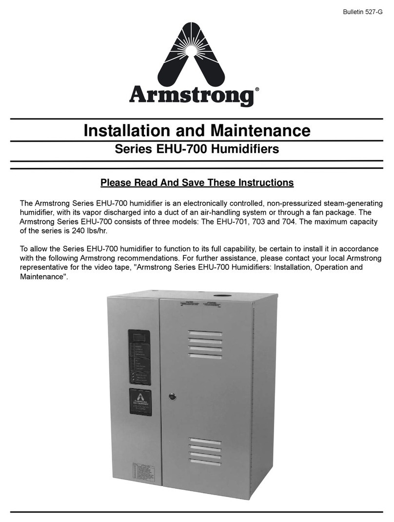
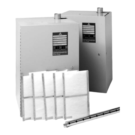
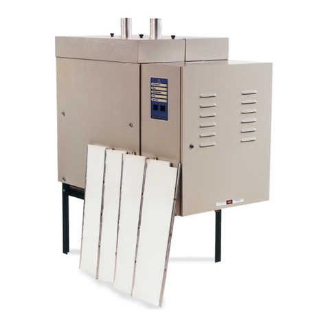
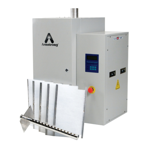
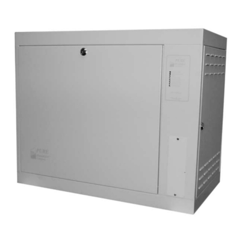
Armstrong EHU-600 Instruction Manual

HUMIDIFICATION
Installation and Maintenance of
Armstrong EHU-600 Series Humidifiers
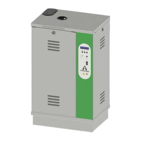
The Armstrong EHU-600 Series humidifier is an electronically controlled,
non-pressurized, electric steam-generating humidifier, with its vapor discharged into a
duct of an air-handling system or through a fan package.
To allow the EHU-600 Series humidifier to function to its full capability, be certain to
install in accordance with Armstrong recommendations.
These installation and maintenance guidelines should be used by experienced person-
nel as a guide to ensure that the Armstrong EHU Humidifier functions correctly. Selection
or installation of equipment should always be accompanied by competent technical
assistance. We encourage you to contact your local representative or Armstrong if further
information is required.
READ AND SAVE THESE INSTRUCTIONS Bulletin No. 526-G

Installation and Maintenance
EHU-600 Series Humidifiers
2
READ AND SAVE THESE INSTRUCTIONS
Table of
Contents
A. Pre-Installation
• • • • • • • • • • • • • • • • • • • • • • • •
Page 3
1. Check shipment
2. Check local codes
3. Site selection
B. Installation
• • • • • • • • • • • • • • • • • • • • • • • • •
Page 4
1. Mounting the humidifier
2. Electrical wiring
3. Water fill supply
4. Drain connection
5. Steam generator
6. Steam dispersion tube
7. Control humidistat
8. High limit duct humidistat
9. Fan interlock switch
10. Wiring diagrams
11. Capacity chart
12. Physical data
13. Submittal drawings
C. Principle of Operation
• • • • • • • • • • • • • • • • • •
Page 15
1. Operation
2. Suggested Specification
3. Display (instrument) panel
D. Start-Up Procedure
• • • • • • • • • • • • • • • • • • • •
Page 19
E. Maintenance
• • • • • • • • • • • • • • • • • • • • • • • • •
Page 22
1. Recommended maintenance schedule
2. Water quality
3. Steam generator cleaning
4. Electrode installation
5. Parts list
F. Diagnostics
• • • • • • • • • • • • • • • • • • • • • • • • • •
Page 29
1. Output circuits
2. Input circuits
G. Humidistat Troubleshooting
• • • • • • • • • • • • • •
Page 31
© Armstrong International, Inc. 2003

Installation and Maintenance
EHU-600 Series Humidifiers
3
Pre-Installation 1. Check Shipment
A claim should be filed with the transportation company (and reported
to Armstrong) if any items are missing or damaged. Your shipment
may consist of as many as four cartons which contain:
a. Humidifier
b. Steam generator(s) (two cartons on Model EHU-602)
c. Steam dispersion tube, Fan Package or HumidiPack
Dispersion Panel.
Allcontrols(controlhumidistat,highlimitstat,etc.)ifordered,areshipped
in a marked package inside the humidifier.
2. Check Local Codes
EHU-600 Series humidifiers should be installed in accordance with
all applicable building, plumbing, and electrical codes.
3. Site Selection (See Fig. 3-1)
Electronic steam humidifiers should be installed in locations that
allow routine inspection and accessibility for maintenance opera-
tions. Armstrong recommends that electronic steam humidifiers
not be placed in false ceilings or in locations where unusual
instances of malfunction of the humidifier or the system might cause
damage to non-repairable, unreplaceable, or priceless property.
Note: Please contact factory for duct applications offering high static pressure (>4" WC).
Figure 3-1: Site Selection - General Installation Concept
Close to Main
Power Disconnect
Valved
Water Supply
Dispersion Tube
Separate Cabinet Drain
with Water Seal EHU-600 & 602 Only
Pitch Drain Piping 1”/12”
on Horizontal Runs
Duct
Steam Piping, 1”/12”
Pitch Piping Back

Installation and Maintenance
EHU-600 Series Humidifiers
4
The mounting surface should be a wall of ordinary
studdedconstruction or otherconstruction of equivalent
strength, capable of supporting the maximum
humidifier weight. Maximum operating weights are:
Model No. Maximum Operating Weight
lb. Kg
EHU-600 80 36
EHU-601 104 47
EHU-602 145 66
EHF-2 32 14.6
EHF-3 33 15
The location should be close enough to the air duct so
that the length of steam hose or pipe is as short as
feasible.Alength of 10 ft. or less is ideal; the maximum
recommendedlengthforrunningcoppertubeis40feet.
See Page 6, Item 6 of the Installation Section for more
details on steam dispersion tube location.
See Figures 4-1 and 4-2 for access space.
The location chosen should be inside with a minimum ambient
temperature of 40°F. and a maximum of 100°F. The unit should have
access to electrical service, a supply of ordinary tap water, and a drain
line for waste water to sewer. The humidifier should not be mounted on
hot surfaces.
Installation
Figure 4-1: Model EHU-600 Access Space
Figure 4-2: Access Space for
EHU-601 and EHU-602
1. Mounting The Humidifier
The EHU-600 Series is intended to be mounted on a wall by means of
3/8" diameter lag screws or other suitable fasteners capable of
supporting the maximum operating weight of the humidifier.
Model EHU-600: Making sure the humidifier is level, hold it against the
mounting surface to mark the hole pattern. Make sure the screws will
go into studs or other sturdy structure. Fasten the humidifier to the wall
using the four 3/8" x 1 1/2" lag screws provided (See Fig. 4-3).
ModelsEHU-601 and EHU-602:Fasten themountingbracket (seeFig.
4-2 and 5-1) to the wall with the two 3/8" x 1 1/2" lag screws provided.
Make sure the screws will go into studs or other sturdy structure. Hang
the humidifier cabinet on the mounting bracket. Install the #8 x 1/2" self
tapping screw from inside the humidifier cabinet so that it goes through
the holes in the cabinet and the mounting bracket. (Model EHU-602
has two screws). This locks the cabinet to the mounting bracket.
2. Electrical Wiring
All wiring installations must be made in accordance with local
codes. Refer to the capacity chart or the name plate on the unit for
Figure 4-3: Mounting Clearances
5"
MIN. DRAIN PAN PIPING
AND REMOVAL
4" Clearance
18" Min. Steam
Generator Tank
Removal
Wall Steam Hose Outlet
4" Clearance
5" Min. Drain Pan Piping
and Removal
24" 24"
5"
18" Min.
Clearance
Right
Side
5" Min.
Clearance See Page 14 for
Drain Connections
WALL
Mounting Bracket
3/8” x 1-1/2” Lag Screws
on 18-1/4” Centers
Wall

Installation and Maintenance
EHU-600 Series Humidifiers
5
recommended branch wire and fuse. See Sections 7, 8 and 9 for
control wiring information. A complete wiring diagram as shown in
Section 11 is located inside the door of the humidifier.
Wiring to thelow-voltagecontrolsshould not runin the sameconduit as
the power supply wiring because faulty signals could result. Shielded
cable is recommended.
Important: Please observe the following:
a. Make certain there is a manually operated interlocking circuit
breaker or safety switch (not furnished) in the electric power
supply Located close to and within sight of the
humidifier.
b. Disconnect the electric power supply at this circuit breaker or
switch whenever the unit is inspected or serviced. Do not use
the switch on the humidifier because this switch
disconnects the steam generator tank only.
c. The voltage and phase of the unit must correspond to the
available voltage and phase.
d. The fuse main breaker must be of sufficient size to handle the
maximum fuse rating as indicated on the specification label on
the unit.
e. Ground the humidifier cabinet; a ground lug is provided in
the wiring compartment.
f. Use only wire with copper conductors rated 90oC or higher
for high voltage and grounding.
g. Avoid running high voltage wire next to PC board. Use bottom
knockout for high voltage wire inlet.
3. Water Fill Supply
a. Only ordinary (potable) tap water should be used. Do not use
brackish or contaminated water.
b. Softened water may not be suitable. The softening process
can produce treated water with conductivity too high.
c. Demineralized,deionized or distilledwaterisnotrecommended
unless it is blended with tap water. Consult factory if you have
one of these water supplies.
d. Humidifier maintenance and performance can be affected by
waterquality.Ideal water conductivityis200 to400micromhos.
Depending on the application (voltage, capacity, etc.), water
conductivitiesbetween50 and 800micromhoshave been used
successfully. Please consult factory if micromhos are over
800. If unsure of water conductivity,Armstrong will test free of
charge. Consult factory.
e. Connect the water supply to the 3/8" tube compression fitting
on the fill valve adapter.
f. Connect the unit to the building water supply (20 to 125 psig
pressure). Install a shut-off valve near the humidifier.
Figure 5-1: Mounting Brackets and
Bolt Locations
EHU-602
EHU-601
8-7/16
2-15/166-15/16 12
1/4 13
16
29-7/8
12
2 x
B
1/4 5 x
B
7/16
1-1/2
7/16
7/16
8-7/16
16
16-7/8
B
1/4 2 x
B
7/16 11/32
1-1/2
7/16
1/4

Installation and Maintenance
EHU-600 Series Humidifiers
6
4. Connect Drain
Connect to a suitable waste draining system, an open drain is recom-
mended. Local plumbing codes may specify details of this connection.
Be sure the drain line is well pitched (recommend 1" per foot) and is
minimum 1" size copper pipe. Do not use PVC pipe. Drain water is hot.
Drain the water where it will not present a hazard to personnel. Be sure
thecabinetdrain(EHU-601/602 only)hasa6"waterseal("P"trap).Note:
A special EPROM is available to temper drain water to 160oF or lower.
Consult factory.
Model EHU-600: Steam generator drain and cabinet drain are the same,
1" O.D.A short piece of 1" I.D. clear hose is provided.
Models EHU-601 and 602: Steam generator drain is 3/4" NPT. Cabinet
drain is 5/8" O.D. (See Section 13 Submittal Drawing).
5. Install Steam Generator
Model EHU-600: The steam generator is shipped installed on the
EHU-600 model. Using wrenches, be sure steam generator tank connec-
tions are installed and tightened according to the tank label (see Fig. 6-1).
Models EHU-601 and 602: The steam generator(s) is shipped
separately on the EHU-601 and 602 models. Make sure the O-ring is
properly placed in the tank drain adaptor (see Fig. 6-2). Insert the bottom
centerconnection ofthe steamgenerator intothe drainadaptor.Connect
the push-on socket plug electrical leads to the electrode connectors
locatedontopofthesteam generator (see Fig.6-3).Makesurethepush-
onplugs aretight (seeFig. 6-4).Remember, a loose joint is a hot joint.
NOTE: Please consult factory for duct applications offering high static
pressure (4" W.C. or greater or high velocity ducts >2000 FPM).
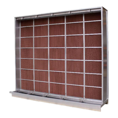
6. Install Steam Dispersion Tube
a. Verify that the proper length and type of steam dispersion tube
has been selected. See Chart 6-1 for proper dispersion tube
lengths. The standard dispersion tube has a built-in slope to allow for
gravity drainage of condensate back to the steam generator (see
Fig. 7-1). When the dispersion tube capacity is greater than 40
lbs/hr the steam flow rate is too high to allow for gravity drainage
and the EHU dispersion tube with 1/2" O.D. drain tube must be
used (see Fig. 7-2).
For dispersion tube without drain: Cut a 1 5/8" diameter hole in
the duct (template provided). See Figure 7-3A.
For the dispersion tube with drain: Cut hole in duct as shown in
Figure 7-3B. Connect 1/4" pipe or 1/2" O.D. tubing to the drain
tube. A template is included for cutting holes in the duct.
b. Select a location on the duct that provides adequate length for
vapor mixing and the shortest connection length to the humidifier.
If steam piping run is more than 20 feet, install a "P" trap drain
every 20 feet (see Fig. 7-5). Maximum piping run is 40 feet.
Figure 6-1: Steam Generator Tank
Connections
Figure 6-2: Generator Tank Installation
Figure 6-3: Electrode Connector
Figure 6-4: Electrode Connector
Push on Plug
Chart 6-1: Selecting Proper Steam
Dispersion Tube
Model EHU- Length Duct Width Weight
600, 601 & 602 O.D. L (cm) Min. Max. lbs. (kg)
D-1 1-1/2" (38) 12" (30) 11" (28) 16" (41) 2 (1)
D-1.5 1-1/2" (38) 18" (46) 17" (43) 22" (56) 2 (1)
D-2 1-1/2" (38) 24" (61) 23" (58) 34" (86) 3 (1.4)
D-3 1-1/2" (38) 36" (91) 35" (89) 46" (117) 4 (2)
D-4 1-1/2" (38) 48" (122) 47" (119) 58" (147) 4 (2)
D-5 1-1/2" (38) 60" (152) 59" (150) 70" (178) 5 (2.3)
D-6 1-1/2" (38) 72" (183) 71" (180) 82" (208) 6 (3)
Use two nuts to hold
power lead terminal – Use
TWO wrenches to tighten
this joint.
Leave space here.
This nut should be
only snug – do not
over tighten.
Steam Generator Tank
Be Sure Feet Set
In Cabinet Firmly
& Level
O-Ring Forms
Water Tight Seal
Tank Drain Adaptor
Tank
Electrode
Wire
Tighten with
1/8” Allen Wrench
Tighten by
Clamping with Pliers
Brass Connector
Unscrew Plastic Cover
Installation and Maintenance
EHU-600 Series Humidifiers
7
Preferably the location should be 6 inches down stream and/or 10 feet
upstream from any dampers, vanes, bends in the duct, or controllers
(i.e.high limitstat).Do notinstall the dispersiontube into ductsin which
airflowexceeds 2,000FPM. Donot restrictairflow inducts witha depth
of 8 inches or less. Avoid placing manifold in downward, high velocity
airflow as dynamic air pressure will restrict steam flow.
The preferred installation of the dispersion tube is above the humidifier
as shown in Figure 7-2. This allows for gravity drainage of condensate
back to the humidifier. Figure 7-4 shows the correct installation when
the steam dispersion tube is below the humidifier. If this installation is
used, a 1 1/4" copper tee may be used for the drain connection (see
Fig. 7-5).
Figure 7-1: Connection at Duct
Figure 7-2: EHU Dispersion Tube
with
1
/
2
" O.D. Drain Tube (For More
Than 40 lb/hr Capacity per Tube)
Figure 7-4: Disperson Tube
Below Steam Outlet on Humidifier
c. Insert the dispersion tube into the duct so the holes face
upward. Never install the tube with the holes facing downward.
Fasten the mounting plate to the outside of the duct with sheet
metal screws. If the dispersion tube is 36" long or more, support
the far end with threaded rod or similar means.
Figure 7-5: 1-1/4" Copper Tee for
Drain Connection
1-3/8
"
O.D.(1-1/4
"
Nom.)
CopperTube
HoseClamps
SteamDispersionTube
HOLESUP
Insulation
HoseCuff
Built In Pitch
"Up"Label
Front
View
Holesin
Manifoldto
beinstalled
in"UP"
position.
Ductabove outlet
6
"
Water
Seal
Floor
Drain
Outlet
EHU
For steam capacity
above 40 lb/hr
For steam capacity
40 lb/hr or less
6.00
6.00
5.25
5.25
Ø .22
4places
Ø 1.75
Holein
duct
Ø.22
4places
6.00 R.88
6.00 3.50
1.00
5.25 R.37
5.25
Hole in duct
2.00
3.50
1.50
6" Waterseal
See Fig. 7-5
AlternateMethod:
1-1/4” Copper Tube
SolderedintoTee
HoseClamp
SteamHose DispensionTube
Hose
1-1/4" CopperTee
Reducer
1/2" or 3/8"
CopperTube
6"
SolderedJoints
Up
ToDrain
Figure 7-3B: For Dispersion Tube
With Drain
Figure 7-3A: For Dispersion Tube
Without Drain

Installation and Maintenance
EHU-600 Series Humidifiers
8
7. Control Humidistat
The Series EHU-600 is compatible with any humidistat with the follow-
ing characteristics:
NOTE: Use of shielded wire or wiring in conduit is recommended for
control wiring.
a. 4-20 Milliamps, See Fig. 8-2 for wiring instructions. Note: Printed
Circuit Board has 500 ohm impedance for this type input signal.
Some 4-20 inputs may require a floating ground. Change stat
grounding selector on PC Board. See Figure 9-1.
b. 2-10 Volts, See Fig. 8-2 for wiring instructions. Note: Printed Circuit
Board has 500 ohm impedance for this type input signal. The load
resistor may be removed to increase input impedance, consult factory.
c. 0-135 Ohms, See Fig. 8-3 for wiring instructions.
d. On/Off, See Fig. 8-4 for wiring instructions.
e. Armstrong Humidistat. See Fig. 8-5 for wiring instructions.
d. Connect the dispersion tube to the steam generator using
minimum 1 1/4" nom. (EHU-600) or 1 1/2" (EHU-601/602) size
hard copper tube (customer supplied) and the two short hoses
supplied with the humidifier. See Figures 7-1 and 8-1. Insulate
the copper tube to minimize condensation. Long runs of pipe
and/or high duct static pressure may require 1 1/2" or 2" copper
pipe. See Figure 8-6.
If the optional 10 ft. flexible steam hose is used, cut the steam
hose to length as required. Wipe out the inside of each hose end
beforeinstalling.Connectthecut end of the hosetothedispersion
tube. Tighten all hose clamps.
e. If duct static pressure and piping back pressure exceeds 4" W.C.
please consult factory for special mounting procedures.
Steam hose or pipe must be free of loops, kinks, and sags to
allow for gravity drainage of condensate. (Provide pitch of 1"
per foot.) Hose supports may be required to accomplish this.
Figure 8-1: Connection at Unit
Figure 8-2:4-20 Milliamps Humidistat
2-10 Volts Humidistat
Please consult factory for additional information on wiring
A18609, A18610, or A17888 Armstrong Humidistats.
Figure 8-4: On/Off Humidistat
Figure 8-3: 0-135 Ohms Humidistat
Figure 8-5: Armstrong Humidistat
Lb. / Hr. Steam
Figure 8-6:
Pressure Loss in Copper Pipe
(40 Feet Equivalent Run)
GND
+Input
500 OHM Input
Impedence ON
4-20 mA/2-10V
Stat. Selection
4-20 mA Stat.
OR
2-10 V Stat.
+5VDC
+Input
Brown
Orange
Opens with Increase
in Humidity
ON/OFF Stat.
AMW Part No.
A-8581 or
A-8581-A
0 – 135 OHM
STAT.
AMW PART NO.
A-8821
HUMIDITY
INCREASE
+5VDC
GND
+INPUT
BLACK
WHITE
RED
Common
1.9-3.9 Vdc. Input
12 Vac Power
White
Green
Black
25 Armstrong
26 Solid State
27 Humidistat
AMW Part No.
C-1471 or
C-1472
1-3/8" O.D. (1-1/4" Nom.)
CopperTube
Insulation
EHU
Cabinet
Top
HoseClamps
RubberHose Cuff
SteamGenerator Tank

Installation and Maintenance
EHU-600 Series Humidifiers
9
The EHU-600 as shipped, is usually set to accept input signals from
the Armstrong control humidistat. To adapt the EHU-600 to a different
type of control humidistat (with characteristics as listed above) jumper
BJ2 must be changed on the printed circuit board (See Fig. 9-1). For
the Armstrong humidistat select the jumper position labeled 1.9-
3.9V. If the desired humidistat has the characteristics 4-20 milliamps
or 2-10 volts, change the jumper position to the position labeled 2-10V/
4-20MA. If the desired humidistat has the characteristics on/off or
0-135 ohms, change the jumper to the position labeled 0-135ΩON/Off.
Make sure main power is off when changing any PC board jumper
setting. See the troubleshooting section of this manual for additional
information on humidistat wiring.
Selecting The Proper Location: The control humidistat should be
located where it will be exposed to the average air condition of the
space to be humidified.Avoid areas of restricted air circulation, or loca-
tions where the sensor will be subjected to air drafts, localized heat, or
moisture sources such as coffee machines, computer blower outlets,
doors to other rooms, or windows that can be opened.
Wall-mounted control humidistats (Armstrong Part C1471) are
usually installed 4 ft. to 5 ft. above floor level. Often, the best location
is beside a thermostat that controls temperature in the same space
that is to be humidified, if that location meets the above criteria.
Duct-mounted control humidistats (Armstrong Part C1472) are also
available for installation where sensing and control from return air
or exhaust air ducts is preferable.
Mounting The Armstrong Control Humidistat
Caution: Do not check humidistat circuit with ohmmeter or direct
current with sensing element installed. Circuit may be checked
without sensor installed.
Wall Mounted Control Humidistat.The wall mountedunit is designed
to mount on a standard electrical outlet box. Mounting screw holes are
provided in the top and the bottom of the back plate. See Fig. 9-2.
Duct Mounted Control Humidistat. The sensor is mounted on the
end of the tube extending into the duct – not beneath the humidistat
cover. The duct mounted control humidistat requires a 1 1/4" diameter
hole in the side of the duct. See Fig. 9-3. See Figure 10-3 or 8-5 for
wiring terminals and overall wiring diagrams.
Operation And Adjustment Of The Armstrong Humidistat.
To set the Armstrong modulating humidistat to maintain a desired
relative humidity, remove the outer plastic cover and verify that the
number/color coded sensor element installed is in the RH control range
desired (see Fig. 10-1). Figure 10-2 specifies the number/color code
and corresponding humidity set point control range for each sensing
Figure 9-1: Location of Selector Pins
on Printed Circuit Board
Figure 9-2: Wall Mounted Control
Humidistat
Figure 9-3: Duct Mounted Control
Humidistat
Capacity Stepping
Selector
Display Connector
Socket
Stat Grounding
Selector
Stat Type
Selector
Test
Capy Step
Normal
Mounts
on std.
2'' x 4'' box
(screws
provided)
Sensor
4-3/8''
2-7/8'' 1-5/8''
2-7/8''
4-3/8''
3-1/2''
4-1/16''
1-1/4'' Max.
Sensor
10''3-5/8''
1.9-3.9 V
2-10V-4-20 MA
0-135 v On/Off
MCM Header
GND
Float

Installation and Maintenance
EHU-600 Series Humidifiers
10
element. (Figure 10-2 can also be found on the inside of the humidistat
cover.)
To set the RH control point within the range of the sensing element, the
jumper wire must be attached to the proper set point pin. There are
nine numbered pins spaced vertically on the right hand side of the
humidstat circuit board; the jumper wire attaches to one of these. By
using Figure 10-2, select the proper pin number to correspond to the
percentage that is to be maintained in the space.
For example, assume that 40% RH is the desired condition and that
the orange colored sensor (15-1213) is in its place in the controller.
From Figure 10-2, it is seen that the horizontal line at 40% intersects
the angular line labeled "orange" closest to the vertical line extending
up from the "5". Once the jumper wire is set to pin 5, replace the cover.
Nowthehumidstat cancontrolthe humidifier steamoutputat the proper
modulated rate to maintain 40% RH.
The humidstat will send a 1.9 to 3.9 Vdc signal to the humidifier as the
space humidity drops from 42.5 to 37.5% RH (+/- 2.5% RH throttling
range). As the humidistat signal varies from 1.9 to 3.9 Vdc the
humidifier demand signal varies from 0 to 100%. For input signals
below 1.9 Vdc the demand stays at 0% and for signals above 3.9 Vdc
the demand stays at 100%.
8. High Limit Duct Humidistat
AductmountedHighLimit Stat(ArmstrongPartA8581)is recommended
as a precaution against localized saturation in the duct. It is an on-off
controllerthat opens the contact on a rise in humidity (opens on fault).
See Figure 10-3 for wiring terminals and overall wiring diagrams.
Figure 10-1: Armstrong Humidistat
Figure 10-2: Control Range for
Sensing Elements
Figure 10-3: Wiring Diagram
13
22
6
7
3
23
2
24
WHITE
GREEN
BLACK
ORANGE
BROWN
Fan Interlock
(i.e. Pressure Switch)
Normally Open
Set Points
Humidistat
Element
High Limit
Humidistat
Controlling Humidistat
In Return Duct or Room
AMW
C-1471
or
C-1472
White
Green
Black
Orange
Brown
13
22
6
7
3
23
2
24

Installation and Maintenance
EHU-600 Series Humidifiers
11
It should be mounted 6 to 10 feet downstream
from the steam dispersion tube(seeFig.11-1).The
high limit stat must be upstream of filters, silencers,
takeoffs, etc. since these devices can reduce duct
humidity and prevent the high limit stat from doing
its job. Complete mountinginstructionsarecontained
in the High Limit Stat package.
Figure 11-1: High Limit
Duct Humidistat
9. Fan Interlock Switch
Afaninterlockswitch is recommended todeactivatethehumidifierwhen
there is insufficient air flow in a duct system.A duct pressure switch is
preferred as a fan interlock device. The pressure switch should open
on insufficient air flow (opens on fault). See Figure 10-3 for wiring
terminals and overall wiring diagrams. Complete installation and
wiring instructions are contained in the duct pressure switch package.
Armstrong Pressure Switch: (Armstrong PartA9023) All Pressure and
electrical connections and set point adjustments are on side for each
installation. Temperature limit: 32°F. to 180°F.
Maximum surge pressure: 10 psig Rated pressure: 45" H2O
Pressure connections: 1/8" NPT Operating range: 0.07 to 0.15" H2O
Installation:
a. Select a location that is free from excessive vibration, corrosive
atmosphere and within temperature limitations.
b. Connect switch from pressure source with tubing (1/4" O.D.
is recommended) to high pressure port. The low pressure port
is left open to atmosphere.
Note: Above procedure is for downstream side of fan
installation. For fan suction side installation, see instructions
accompanying switch.
c. Electrical connections to the switch are provided by means of
screw terminals marked common and normally open. The
normallyopencontacts close whenpressureincreases beyond
the set point.
d. Complete instructions are contained in the pressure switch
package.
Note: Limit switches (high limit and fan interlock switches) open
on fault.
NOT LESS THAN 6 FEET, NOT MORE THAN 10 FEET
Air Flow
Dispersion Tube High Limit
Humidistat
Duct

Installation and Maintenance
EHU-600 Series Humidifiers
12
10. Wiring Diagram
Figure 12-1: EHU-600 Wiring Diagram

Installation and Maintenance
EHU-600 Series Humidifiers
13
Materials
GeneratorTank Polypropylene
Cabinet Steel-18 GA with Epoxy Enamel Coating
Electrodes Type 430 Stainless Steel
Hose Cuffs EPDM Rubber
Duct Model
DispersonTube Type 18-8 Stainless Steel
Area Fan Unit Model
EHF-2,3 Cabinet Steel –18 GA with Epoxy Enamel Coating
EHF-2 115 VAC, 60 Hz, 1.3 amp
BlowerFan 280 CFM @ 1380 RPM
EHF-3 115 VAC, 60 Hz, 2.9 amp
BlowerFan 465 CFM @ 1530 RPM
11. Capacity Chart
Chart 13-1: EHU-600 Series Capacities and Nominal Amperage Ratings
Output lb./hr. (kg/hr.) @ Voltage
Recommended
Nom * Branch Circuit Single Phase Three Phase
Amp MCM
Rating Module Wire Fuse 120 208 240 277 208 240 346 1380 415 2480 600
Model EHU-600 Humidifiers (One Steam Generator)
7.0 7 14 15 2.1(.9) 3.7 (1.7) 4.3 (2) 5 (2.3) 6 (2.7) 7 (3.2) 12 (5.5) 15 (6.8) 18 (8.2)
10.9 6 14 15 3.3(1.5) 6 (2.7) 7 (3.2) 8 (3.6) 10 (4.6) 12 (5.5) 18 (8.2) 23 (10.5) 29 (13.2)
14.6 1 15 20 4.5(2) 8 (3.6) 9 (4.1) 10 (4.6) 13 (5.9) 15 (6.8) 24 (11) 31 (14) 39 (17.8)
18.2 2 10 25 10 (4.6) 11 (5) 13 (5.9) 17 (7.7) 19 (8.7) 30 (13.7) 38 (17.3)
21.9 3 10 30 12 (5.5) 13 (5.9) 15 (6.8) 20 (9.1) 23 (10.5) 37 (16.8)
32.7 4 8 45 17 (7.7) 20 (9.1) 23 (10.5) 30 (13.7) 35 (16)
36.3 5 8 50 19 (8.7) 22 (10) 26 (11.8) 33 (15) 38 (17.3)
Model EHU-601 Humidifiers (One Steam Generator)
18.2 2 10 25 10 (4.6) 11 (5) 13 (5.9) 17 (7.7) 19 (8.7) 28 (12.8) 30 (13.7) 33 (15) 38 (17.3) 48 (21.9)
21.9 3 10 30 12 (5.5) 13 (5.9) 15 (6.8) 20 (9.1) 23 (10.5) 33 (15) 37 (16.8) 40 (18.2) 46 (21) 58 (26.4)
32.7 4 8 45 17 (7.7) 20 (9.1) 23 (10.5) 30 (13.7) 35 (16) 50 (22.8) 55 (25) 60 (27.3) 69 (31.4) 86 (39.2)
36.3 5 8 50 19 (8.7) 22 (10) 26 (11.8) 33 (15) 38 (17.3) 55 (25) 61 (27.8) 66 (30) 77 (35) 96 (43.7)
42.0 8 6 60 22 (10) 26 (11.8) 30 (13.7) 38 (17.3) 44 (20) 64 (29) 70 (32) 77 (35) 89 (40.5)
45.0 9 6 60 24 (11) 28 (12.8) 32 (14.6) 41 (18.7) 48 (21.9) 69 (31.4) 75 (34) 82 (37.3) 95 (43.3)
48.0 10 6 70 25 (11.4) 29 (13.2) 34 (15.5) 44 (20) 51 (23.2) 73 (33.2) 80 (36.4) 88 (40)
Model EHU-602 Humidifiers (Two Steam Generators)
36.4 2 8 50 19 (8.7) 22 (10) 26 (11.8) 33 (15) 38 (17.3) 55 (25) 61 (27.8) 66 (30) 77 (35) 96 (43.7)
43.8 3 6 60 23 (10.5) 27 (12.3) 31 (14) 40 (18.2) 46 (21) 67 (30.5) 73 (33.2) 80 (36.4) 93 (42.3) 116 (53)
65.4 4 3 100 35 (16) 40 (18.2) 46 (20.9) 60 (27.3) 69 (31.4) 100 (45.5) 109 (49.6) 119 (54) 138 (62.8) 173 (79)
72.6 5 3 100 39 (17.8) 44 (20) 51 (23.2) 66 (30) 77 (35) 111 (50.5) 121 (55) 133 (60.5) 153 (69.7) 192 (87.4)
84.0 8 2 125 45 (20.5) 51 (23.2) 59 (26.9) 77 (35) 89 (40.5) 128 (58.3) 140 (63.8) 153 (69.7) 177 (80.6)
90.0 9 2 125 48 (21.9) 55 (25) 64 (29) 82 (37.3) 95 (43.3) 137 (62.4) 150 (68.3) 164 (75.7) 190 (86.5)
Notes:
(1) 346 volt units require 346/200 volt 4 wire system. (2) 415 volt units require 415/240 volt 4 wire system.
KW rating = humidity output (lb./hr.) x 0.345 (for energy calculations only; not for branch circuit sizing).
*Nominal Amp Rating is for breaker sizing and UL purposes only. Average operating amperage is 88% of normal rating.
Capacitieis listed in table are based on average amperage draw.
12. Physical Data
Chart 13-2: Series EHU-600, EHF-2 and EHF-3 Fan Packages
Weights
Approximate Maximum
Model No. Shipping Operating
lb kg lb kg
EHU-600 60 27 80 36
EHU-601 76 35 104 47
EHU-602 87 40 145 66
EHF-2 33 15 32 14.6
EHF-3 34 15.5 33 15

Installation and Maintenance
EHU-600 Series Humidifiers
14
13. Submittal Drawings
Chart 14:1 Dimensional Data
EHU-600 EHU-601 EHU-602
in mm in mm in mm
"A" Width 18 457 18 457 31 787
"B" Height 23 584 281/2724 281/2724
"C" Depth 111/2292 1311/32 339 1311/32 339
"D" Tank Drain (Side) 65/8168 63/16 157 63/16 157
"E" Tank Drain (Front) 105/16 262 81/4210 81/4210
"F" Cabinet Drain 5/8" OD N/A N/A 111/2292 18 457
"G" Tank #2 Drain (Front) N/A N/A N/A N/A 213/16 538
"H" Steam Outlet #1 121/2318 111/2292 111/2292
"I" Steam Outlet #2 N/A N/A N/A N/A 13 330
"J" Water Supply* (Side) 81/4210 913/16 249 913/16 249
"K" Water Supply* (Front) 151/2394 35/16 84 35/16 84
"L" Electrical Supply (Side) 31/880 2 51 2 51
"M" Electrical Supply (Front) 41/2114 21/264 21/264
"N" Fan Height (EHF-2) 13 330 N/A N/A N/A N/A
"N" Fan Height (EHF-3) 16 406 Remote Installation Only
"P" Front Clearance 18 457 24 610 24 610
"Q" Left Clearance 4 102 24 610 24 610
"R" Bottom Clearance 5 127 5 127 5 127
"S" Right Clearance 4 102 4 102 4 102
*Water Supply Conn. 3/8" Compression.
Unit is designed to mount on 16" centers.
2 lag screws are provided for EHU-600.
2 lag screws & bracket are provided for EHU-601 & 602.
Figure 14-1 Model EHU-600
(Front and Side View)
Figure 14-2: Model EHU-601 Figure 14-3: Model EHU-602
(Front and Side View) (Front View)
R
5/8'' O.D. Cabinet
Drain
3/4'' NPT
Tank Drain
1-1/2” I.D.
Hose Cuff
TANK DRAIN
1Z\x"I.D.
Hose Cuff
3/4" NPT
Tank Drain
5/8” O.D.
Cabinet Drain

Installation and Maintenance
EHU-600 Series Humidifiers
15
Principle of
Operation
Figure 15-1: 100% demand. Filling with
water low, increasing steam output.
Figure 15-2: 100% demand. Fill valve
cycling to maintain output. High water
level. High, constant steam output.
Figure 15-3: No demand. Contactor opens.
No steam output.
1. Operation
The Armstrong EHU-600 Series electronic steam humidifier
converts ordinary tap water to steam and distributes it within
the air being humidified to bring the relative humidity up to the
desired level. It is the ideal solution for providing humidifi-
cation where no steam is available or where a steam source is
too remote for easy or economical piping. The Armstrong
EHU-600 Series consists of three models: The EHU-600, 601
and 602. The maximum capacity of the series is 192 lb/hr.
The humidity demand, sensed by the humidistat, is indicated
by the EHU demand meter. The microprocessor converts this
demand signal into an amperage requirement. The power
contactor closes, applying voltage to the electrodes, and the
fill valve begins to fill the tank.
Water enters the bottom of the steam generator tank and rises
until it reaches the electrodes. Upon contact, electrical current
flows through the water, causing it to boil and produce steam
(Fig. 15-1).
When the water level rises, as shown in Fig. 15-2, increased
electrical current flows through the water, producing more
steam. This increase will continue until the required output
of steam (i.e. amperage requirement) is reached.
At this point, the fill valve will cycle off and on to maintain the
required amperage. When the humidistat senses the added
moisture in the air, the demand for humidity begins to drop.As
the demand drops, the output of the unit is modulated down by
boiling away water and not filling, allowing amperage to
decrease, thereby reducing the steam flow. The fill valve can
then cycle at the lower steam output (amperage) requirement.
Fig. 15-3 shows what happens when the humidistat demand
signal drops below a minimum demand: The contactor is
de-energized, and steam output stops.
Steam output may also be stopped by a duct high-limit
humidistat or a fan interlock switch. These devices prevent
excess moisture and condensation in the duct. If these devices
open, the Tank Off light will illuminate and the fill will turn off.
Ahigh-water float switchprevents water carryoverintothe duct
due to too high a water level in the tank. When the high water
level is reached the TANK FULL light comes on and the fill
valve is blocked until some water is boiled away and the
water level drops. This is not uncommon on startup. If the
TANK FULL light is on continuously during normal service
then the tank probably needs cleaning.

Installation and Maintenance
EHU-600 Series Humidifiers
16
An automatic drain cycle blows down mineral-laden water to increase
tank life and reduce maintenance requirements. If the water in the
steam generator is not very conductive it will reach the high water
level. The drain duration is adjusted based on how often the high water
level is reached.
An overcurrent protection circuit will drain water from the tank to reduce
current flow and then de-energize the contactor to stop current flow if
overcurrent still exists.
The EHU-600 Series has a patented self-regulating maximum output
feature that eliminates manual adjustment and improves humidity
control.Inlowdemand situations, unitswithgreatercapacitycan quickly
overshoot setpoint because a fraction of the output satisfies the
requirement.Thison-again/off-againbehavioriscalled"hunting"because
the unit has difficulty attaining setpoint. The EHU-600 Series
automatically adjusts maximum output up or down depending on the
humidity demand history. If this feature is not desired it can be easily
over ridden by changing the position of jumper BJ3 on the printed
circuit board from CAPY STEP/NORMAL to CAPY STEP/TEST.
Make sure main power is turned off whenever changing jumpers
on PC board.

Installation and Maintenance
EHU-600 Series Humidifiers
17
2. Suggested Specification
Steam humidifier for distribution of humidity (steam vapor) into air handling system or directly into space
shall be of the self-contained, electronically controlled design.
a. Humidifier shall generate steam from ordinary tap water.
b. Humidifier(s) shall have all internal components contained in a steel cabinet with a key-locked
access door to prevent unauthorized access.
c. Humidifier(s) shall be UL and CUL listed.
d. Humidifier shall have modulating control to provide 10 to 100% capacity.
e. Maximum capacity of humidifier shall self regulate with no manual adjustment.
f. Humidifier shall have steam generator(s) that can be taken apart for inspections and cleaning, or
if needed, replacement of internal parts.
g. Drain cycle will be self regulating for automatic control of mineral (conductivity) buildup.
h. Humidifier shall have programmed diagnostics to confirm that input and output circuits are func-
tioning.
i. Humidifier shall incorporate a demand meter to display status of main control humidistat signal.
j. The electronic circuit shall provide automatic protection from excessive current and high water
overflow.
k. The humidifier fill water line(s) shall have an air gap to prevent backflow (syphoning) of contami-
nated water into the water supply system.
l. Humidifier shall incorporate electrical terminals for installation of controlling stat, duct high-limit
stat and fan interlock switch.
m. Humidifier shall be supplied with stainless steel steam dispersion tube(s) which provide uniform
steam distribution over the entire tube length and shall be supplied at various lengths (through
6 feet) to adequately span the widest dimension of the duct.
n. When applicable, humidifier(s) shall have provisions for discharging steam vapor directly into
room area using factory available fan distribution units as an accessory. These units shall be
designed for either remote mounting or fit directly on top of humidifier.
o. Humidifier shall be supplied with two hose cuffs for connection to hard copper tube (customer
supplied). 1 1/2" ID flexible rubber hose shall be available as an optional item.
p. Humidifier shall be supplied with a humidistat capable of modulating the steam flow, or be capable
of working with the following common control signals without factory modification: 0-135 ohms,
2-10 Vdc, 4-20 milliamp and on/off control (SPST relay).

Installation and Maintenance
EHU-600 Series Humidifiers
18
3. Instrument Panel
"Power" Light – Indicates when the electrical supply is energized.
"Fill" Light – Indicates when the fill valve is energized to add water to
the steam generator.
"Drain" Light – Indicates when the drain valve is energized to drain
water from the steam generator. Note: Drain light does not turn on
when manual drain switch is energized.
"Tank Full" Light – Indicates that the water level in the generator has
risen to the high water float switch. The electronic controls automatically
interrupt the fill cycle to prevent overflow. This may be a normal
occurrence with a brand new or recently cleaned steam generator,
especially if the water conductivity is low and amperage requirements
are high. After a few days of operation the water level should drop
below the high water level due to mineral (conductivity) build up in the
tank. To temporarily increase tank water conductivity a small amount
of salt can be added to the tank water. After extended use, repeated
lighting of the Tank Full light indicates that, in spite of periodic draining
of mineral-laden water, the steam generator should be inspected,
and either cleaned or replaced.
Note: When the Tank Full light is on, the unit may not be able to
generate a sufficient supply of steam to satisfy the demand.
"Tank Off" Light – Indicates when power to the generator has been
interrupted. This may be due to low demand, high duct humidity
interlock, fan interlock, high current, or failed drain system.
"Demand Meter" – Indicates thedemand forhumidity in relationto the
RH set on the humidistat. The demand meter for the EHU-600 is a
series of 5 LED's which indicate demands of 10%-30%, 30%-50%,
50%-70%, 70%-90%, and 90%-100%.
"Tank On/Off" – Pushing and releasing the top part of the black switch
startsthehumidifieror resets the internalovercurrentprotection.Pushing
and holding the TANK ON/OFF switch for 15 seconds starts the
diagnostics system. See the section on Maintenance.
"Manual Drain" – Pushing and holding the bottom part of the black
switch activates the manual drain. Note: Drain light will not illuminate
during the manual drain.
Figure 18-1: Instrument Panel

Installation and Maintenance
EHU-600 Series Humidifiers
19
Start-Up
Procedure
Figure 19-1: Electrical Component
Identification
(Model EHU-602 shown)
Figure 19-2: Humidistat Element
The following steps should be performed on all newly installed EHU
Humidifier units to ensure that the humidifier functions correctly.
1. Turn power supply at disconnect off.
2. Open the two doors.
3. Examine the wiring and the components in the electrical
compartment.
4. Check for anyloosewiresor quick-connect terminalsthatmayhave
been pulled loose.
5. Using a screwdriver, Tighten All Screw Terminals on the power
supply terminal block, ground lug, and contactor (See Figure
19-1) to ensure that no connections have become loose during
shipping.
Make sure steam generator tank connections are installed and
tightened according to the installation instructions (see pg. 6
installation step 5). Remember, a loose joint is a HOT joint and
could be a fire hazard!
6. Locate the "Low Voltage Terminal Block" (See Figure 19-1).
7. Disconnect the control wiring to terminals 3 and 23 (High Limit
Humidistat) and terminals 2 and 24 (Air Proving Switch), then
jumper them out with the tabs provided, or a short piece of wire.
8. Turn on the water supply – Check for leaks.
9. Turn power supply on. The following should now happen:
a. The "Power" and "Tank Off" lights will now be momentarily
illuminated.
b. The "Tank Off" light will go out and the "Fill Light" will go on.
Unit will begin to fill.
c. If the unit does not begin filling, force a 100% humidity demand
by removing the humidistat element (See Figure 19-2). The
unit will then start to fill, and the "Tank Off" light will go out. If
not, the humidistat may be wired incorrectly or may not be the
Armstrong humidistat. See troubleshooting section of this
manual for more information on humidistat wiring.
NOTE: If the humidistat is not the standard Armstrong stat,
the method of forcing a demand signal will be different.
Generally, increasing the humidity set point on the humidistat
will generate a demand signal. Check with the control system
contractor for information.
Contactors
Current
Transformers
Low
Voltage
Terminal
Block
Power
Supply
Terminal
Block

Installation and Maintenance
EHU-600 Series Humidifiers
20
Another method of forcing a 100% demand is to remove the
controller input signal from terminal 6, jumper terminal 13
to terminal 6 with a short piece of wire, and select either
1.9-3.9Vdc or on/off control setting on the main circuit board.
10. While the tank is filling, open terminals 2 and 24 with a screw-
driver, loosening and removing the jumper. The fill will stop and the
"Tank Off" light will come on. Replace jumper; within 10 seconds
the contactor will pull in and the fill will resume.
11. Repeat with terminals 3 and 23. The response will be identical to
Step 10.
12. Let the unit continue to fill and allow to boil.
a. If the water level reaches within 4" of the steam generator
tank top, the high level float switch will block the fill, and
illuminate the "Tank Full" light. This is normal on relatively
pure water, but to complete the start-up testing, push and hold
the drain switch to drain 1/2 of the tank, then, with power off,
add one pinch (1/4 teaspoon)of salttothe fill cup.This should
allow the water to boil by increasing the water's conductivity.
b. If "Tank Full" light illuminates with water level below midway
point in the tank, the back pressure due to duct static or steam
dispersion piping is too high. Consult factory.
13. On typical beginning fill, after the fill stops, using an ammeter, the
tank leads will each be drawing between 35-40% of "nominal amp
rating" at this point. (See unit label for nominal amp rating.)
14. Press the drain switch. Verify that the unit is drawing freely. Be
sure the drain line is well pitched and is 1" size copper pipe. Do
NOTE use PVC pipe.
15. Install the humidstat element, or verify that it is in place.
16. Verify that the humidity set-point is at the desired value.
17. Blow "humidly" on the humidstat element. The following should
happen:
a. The demand meter will go to zero.
b. The unit will shut down, lighting the "Tank Off" light.
c. The unit may energize again after the sensor "dries" out.
The demand meter indicates the humidstat signal, so once
the sensor "dries out" the demand will climb back to 100%
(maybe less if the humidity level is within the control range of
the humidity setting.)
18. Reconnect the air proving switch to terminals 2 and 24. Verify
that the air proving switch is wired to that it opens on no air flow
and is closed with air flow (normally open).
This manual suits for next models
4
Table of contents
Other Armstrong Humidifier manuals

Armstrong
Armstrong EHU-700 Series Instruction Manual

Armstrong
Armstrong C-1801 User manual

Armstrong
Armstrong Series HC- 6100 Manual

Armstrong
Armstrong HumidiClean HC-6700 Series Manual

Armstrong
Armstrong EM-1000 Series Owner's manual

Armstrong
Armstrong Gas Fired HumidiClean Series Manual

Armstrong
Armstrong ElectroVap ERS-LC User manual

Armstrong
Armstrong EHU-800 Series User manual

Armstrong
Armstrong AM-91A Owner's manual

Armstrong
Armstrong HumidiClean HC-4100 Series Manual