AA
9
H\
Armstrong No. 800 BVSW Series
Inverted Bucket Air Traps
-
A~~~Q9~~
Installation, Operation
&
Maintenance Data
PRELIMINARY
Moisture is always present in compressed
air. Oil is
almost
always present at some
points in a compressed air system.
Moisture and oil must be removed from
the system for efficient operation and
long life of gaskets, hoses, and air tools.
Efficient moisture and oil removal that
will forestall trouble requires:
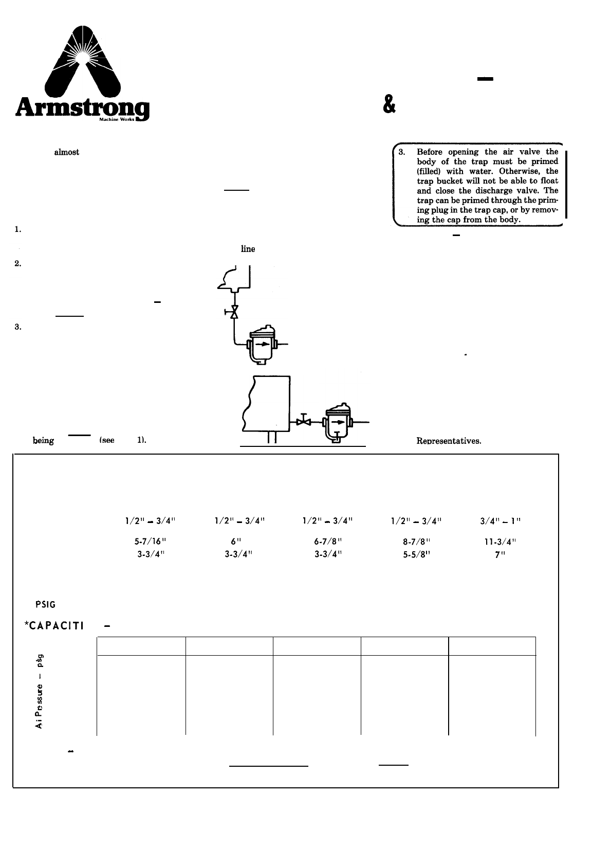
directed by the equipment manufac-
turer. Traps should be accessible to
the maintenance man. If lack of
headroom prevents trap installation
below a receiver, install as shown in
Fig. 2. If trap must be installed
above the dram connection, an inter-
nal check valve or swing check is us-
ed to prevent trap prime loss when
air pressure drops.
pipe cuttings, scale, and dirt. Last of
all, screw the trap into position.
Aftercoolers to bring the compressed
air down to ambient or room
temperature.
2.
Separators to knock down suspend-
ed droplets of water or fog.
First install piping and shut-off
valve ahead of trap, then blow down
the
line
at full pressure to remove
A
4.
Caution
-
since the trap operates
with the body full of water, do not in-
stall where freezing can occur unless
proper non-freeze precautions are
taken.
Separators are installed downstream
from aftercoolers or in an air line
near point of use, or both. Note
-
air
traps are not separators.
Air Traps to discharge the liquid
from the system with a minimum
loss of air.
Fig. 1
TRAP INSPECTION
AND MAINTENANCE
1.
Check trap operation periodically.
Determine that body is full of water
(trap is primed).
2.
If examination shows heavy coating
.
To
get the best results from Armstrong
Inverted Bucket Air Traps, please
observe the recommendations given
below.
INSTALLATION
1.
Inverted Bucket Air Traps should be
installed below and close to the unit
heirw
drained
lsee
Fie.
II.
or as
Fig. 2
x-
of oil
on mechanism, arrange to clean
at regular intervals. Clean body and
cap as well as mechanism.
3.
Examine mechanism at least once a
year to determine tightness of valve
and seat and if any parts require
replacement. If repairs are
necessary, contact your Armstrong
Renresentatives.
-
----o
PHYSICAL DATA
MODEL
CONNECTION
PIPE
CONNECTION
SIZE
HEIGHT
DIAMETER
WEIGHT
MAXIMUM
OPERATING
PRESSURE
NO. 800 NO. 801
HORIZONTAL RIGHT ANGLE
l/2”
-
3/4”
l/2”
-
3/4”
S-7/1
6” 6”
3-3/4” 3-3/4”
5 Ibs. 5 Ibs.
NO.811
HORIZONTAL
l/2”
-
3/4”
6-7/8”
3-3/4”
6 Ibs.
NO. 812
HORIZONTAL
l/2”
-
3/4”
8-7/8”
5-5/8
”
15 Ibs.
NO.813
HORIZONTAL
3/4”
-
1”
l l-3/4”
7”
27 Ibs.
150 150 250 250 250
PSIG
*CAPACI
TI
ES
-
Pounds of Water Per Hour
NO. 800 NO. 801 NO.811 NO. 812 NO. 813
.E”
2
15 1300 1300 2400 3500 9000
I
30 800 800 1800 3200 7000
280 1300 1300 1300 2000 6500
:
ul
125 1300 1300 1600 2500 6500
0
a’
150 1000 1000 1400 1800 5500
_
2
250 1700 1800 5000
*Capacity
-
Mere water handling capacity is not the whole story. The No.813 is the smallest inverted bucket air trop with
sufficient power to give dependable service when heavy oil is present with the water. Do not use smaller traps if heavy oil
is present in your air system.


