Series 21 & 71
Fixed Pivot & Snap Action Liquid Drainers
Entwässerer mit Fixem oder Federbelastetem Hebelmechanismus
Purgeurs de Liquide à Axe Fixe et à Action Rapide
Drenadores de Líquido de Pivote Fijo y Acción Rápida
Vloeistoflozers - met Vast Draaipunt & 'Snap Action' Veer
Scaricatori di Liquido da Gas in Pressione
These instructions should be used by experienced personnel !
Diese Gebrauchsanweisung ist durch Fachpersonal zu benutzen !
Ces instructions devraient être utilisées par du personnel expérimenté !
¡Estas instrucciones deben ser utilizadas por personal experimentado !
Onderhoud uitsluitend uit te voeren door ervaren personeel !
Queste istruzioni devono essere utilizzate da personale esperto !
Model shown on the picture: 21 - Die Abbildung zeigt das Modell 21 - Photo: modèle 21
Modelo mostrado en la fotografía: 21 - Model op foto: 21 - Modello in figura: 21
21: Armstrong Cast Iron Fixed Pivot Liquid Drainer
71: Armstrong Cast Iron Snap Action Liquid Drainer
2 Connections (Top Inlet - Bottom Outlet) or (71-A Only) 3 Connections (Side Inlet - Top
Gas Outlet - Bottom Liquid Outlet)
21: Armstrong Entwässerer mit Fixem Hebelmechanismus aus Grauguß
71: Armstrong Entwässerer mit Federbelastetem Hebelmechanismus aus Grauguß
2 Anschlußarten (Einlaß Oben - Auslaß Unten) oder (nur 71-A) 3 Anschlußarten (Seitlicher
Einlaß - Entlüftung Oben - Abfluß Unten)
21: Purgeur de Liquide Armstrong en Fonte, à Axe Fixe
71: Purgeur de Liquide Armstrong en Fonte, à Action Rapide
2 Raccordements (Entrée par le Haut - Sortie vers le Bas) ou (Uniquement pour 71-A)
3 Raccordements (Entrée sur le Côté - Évent Dessus - Liquide vers le Bas)
21: Drenador de Pivote Fijo Armstrong en Fundición
71: Drenador de Acción Rápida Armstrong en Fundición
2 Conexiones (Entrada Superior - Salida Inferior) o (71-A Únicamente) 3 Conexiones
(Entrada Lateral - Salida de Gas Superior - Salida de Líquido Inferior)
21: Armstrong Gietijzeren Vloeistoflozer met Vast Draaipunt
71: Armstrong Gietijzeren Vloeistoflozer met 'Snap Action' Veer
2 Aansluitingen (Top Inlaat - Bodem Uitlaat) of (71-A Allen) 3 Aansluitingen (Zijde Inlaat
- Top Ontluchting - Bodem Vloeistof Uitlaat)
21: Scaricatore di Liquidi da Gas in Pressione - in Ghisa
71: Scaricatore di Liquidi da Gas in Pressione - in Ghisa
2 Connessioni (Entrata in Alto - Uscita al Fondo) o (Solo 71-A) 3 Connessioni (Entrata
Laterale - Uscita Aria in Alto - Scarico Liquido/Bilanciamento sul Fondo)
For detailed material specifications, options, approximate dimensions and weights, see Armstrong literature or consult your local Representative.
Für detaillierte Werkstoffangaben, Zubehör, Abmessungen und Gewichte, sehen Sie die Armstrong Datenblätter oder fragen Sie Ihre Armstrong-Vertretung.
Pour toute spécification détaillée des matières, options, dimensions et poids, veuillez vous référer à la littérature Armstrong ou prendre contact avec votre
Représentant local.
Para especificaciones de materiales detalladas, opciones, dimensiones aproximadas y pesos, ver catálogos Armstrong o consultar con su
Representante local.
Voor gedetailleerde materiaal specificaties, afmetingen en gewichten, zie de Armstrong documentatie of neem contact op met uw plaatselijke
Vertegenwoordiger.
Per la specifica dettagliata dei materiali, accessori opzionali, dimensioni e pesi approssimativi, vedere la documentazione appropriata o contattare il
Distributore locale.
PRODUCT DESCRIPTION - PRODUKTBESCHREIBUNG - DESCRIPTION DU PRODUIT
DESCRIPCION DEL PRODUCTO - PRODUKT OMSCHRIJVING - DESCRIZIONE DEL PRODOTTO
Armstrong International S.A., Parc Industriel des Hauts-Sarts, 4040 Herstal - Belgium Ph: +32.4.240.90.90 Fax: +32.4.248.13.61
IOM-1087-B 10/2005 www.armstrong.be Printed in Belgium
I. 21: Entretien des pièces internes :
- Enlever le purgeur de la conduite;
- Dévisser les boulons (9) et les écrous (8) et enlever le couvercle (1) avec
le mécanisme qui y est attaché;
-Dévisser le siège (3) et remplacer l’équipement mobile complet (3, 4, 5);
- Revisser le siège (3) et s'assurer que le levier (5) soit aligné dans l'axe
du couvercle (1). Un espace de 0,1 mm doit être laissé pour que le levier
(5) puisse se mouvoir horizontalement;
- Remplacer le flotteur (6) si nécessaire;
- Remplacer le joint de corps (7);
- Replacer le couvercle (1) sur le corps (2) et revisser les boulons (9) et
les écrous (8).
II. 71: Entretien des pièces internes :
- Enlever le purgeur de la conduite;
- Dévisser les boulons (10) et les écrous (9) et enlever le couvercle (1)
avec le mécanisme qui y est attaché;
-Dévisser les 2 boulons du mécanisme et remplacer l’équipement mobile
complet(3, 4, 5, 6);
- Revisser les 2 boulons du mécanisme et vérifier que la soupape (4) se
ferme de manière étanche au centre du siège (3);
- Remplacer le flotteur (7) si nécessaire;
- Remplacer le joint de corps (8);
- Replacer le couvercle (1) sur le corps (2) et revisser les boulons
(10) et les écrous (9).
I. Manutenzione degli organi interni (21):
- Smontare dalla linea l'intero scaricatore;
- Svitare i bulloni (9), i dadi (8) e sollevare la testa (1) con il meccanismo
fissato su di essa;
- Svitare la sede valvola (3) e sostituire l'intero meccanismo (3, 4, 5) senza
il galleggiante;
- Riavvitare la sede (3) ed assicurarsi che la leva (5) sia allineata sull'asse
della testa (1). Per permettere alla leva (5) di muoversi orizzontalmente
bisogna lasciare una luce di 0,1 mm;
- Sostituire il galleggiante (6), se necessario;
- Sostituire la guarnizione (7);
- Rimontare la testa (1) sul corpo (2) ed avvitare bulloni (9) e dadi (8).
II. Manutenzione degli organi interni (71):
- Smontare dalla linea l'intero scaricatore;
- Svitare i bulloni (10), i dadi (9) e sollevare la testa (1) con il meccanismo
fissato su di essa;
- Svitare i 2 bulloni del meccanismo e sostituirlo per intero (3, 4, 5, 6),
senza il galleggiante;
- Riavvitare i 2 bulloni del meccanismo ed assicurarsi che la valvola (4) sia
fermamente chiusa e centrata sulla sede (3);
- Sostituire il galleggiante (7), se necessario;
- Sostituire la guarnizione (8);
-Rimontare la testa (1) sul corpo (2) ed avvitare bulloni (10) e
dadi (9).
I. 21: Wartung und Reparatur:
- Komplette Armatur aus der Rohrleitung ausbauen;
- Schrauben (9) und Muttern (8) lösen, Deckel (1) und Mechanismus
abnehmen;
- Sitz (3) abschrauben und gesamten Mechanismus ohne Schwimmer
austauschen (3, 4, 5);
- Sitz (3) wieder montieren, wobei der Hebel (5) auf die Achse des Deckels
(1) ausgerichtet sein muß. Für die horizontale Bewegung des Hebels (5)
einen Abstand von 0,1 mm lassen.
- Schwimmer (6) bei Bedarf erneuern;
- Gehäusedichtung (7) erneuern;
- Deckel (1) auf das Gehäuse (2) setzen, Schrauben (9) und Muttern (8)
wieder anziehen.
II. 71: Wartung und Reparatur:
- Komplette Armatur aus der Rohrleitung ausbauen;
-Schrauben (10) und Muttern (9) lösen, Deckel (1) und Mechanismus
abnehmen;
- Schrauben 2 von Mechanismus abschrauben und gesamten Mechanismus
ohne Schwimmer austauschen (3, 4, 5, 6);
- Mechanismus wieder mit den 2 Schrauben befestigen und sicherstellen,
daß Ventil (4) in Sitzmitte fest schließt (3);
- Schwimmer (7) bei Bedarf erneuern;
- Gehäusedichtung (8) erneuern;
- Deckel (1) auf das Gehäuse (2) setzen, Schrauben (10) und
Muttern (9) wieder anziehen.
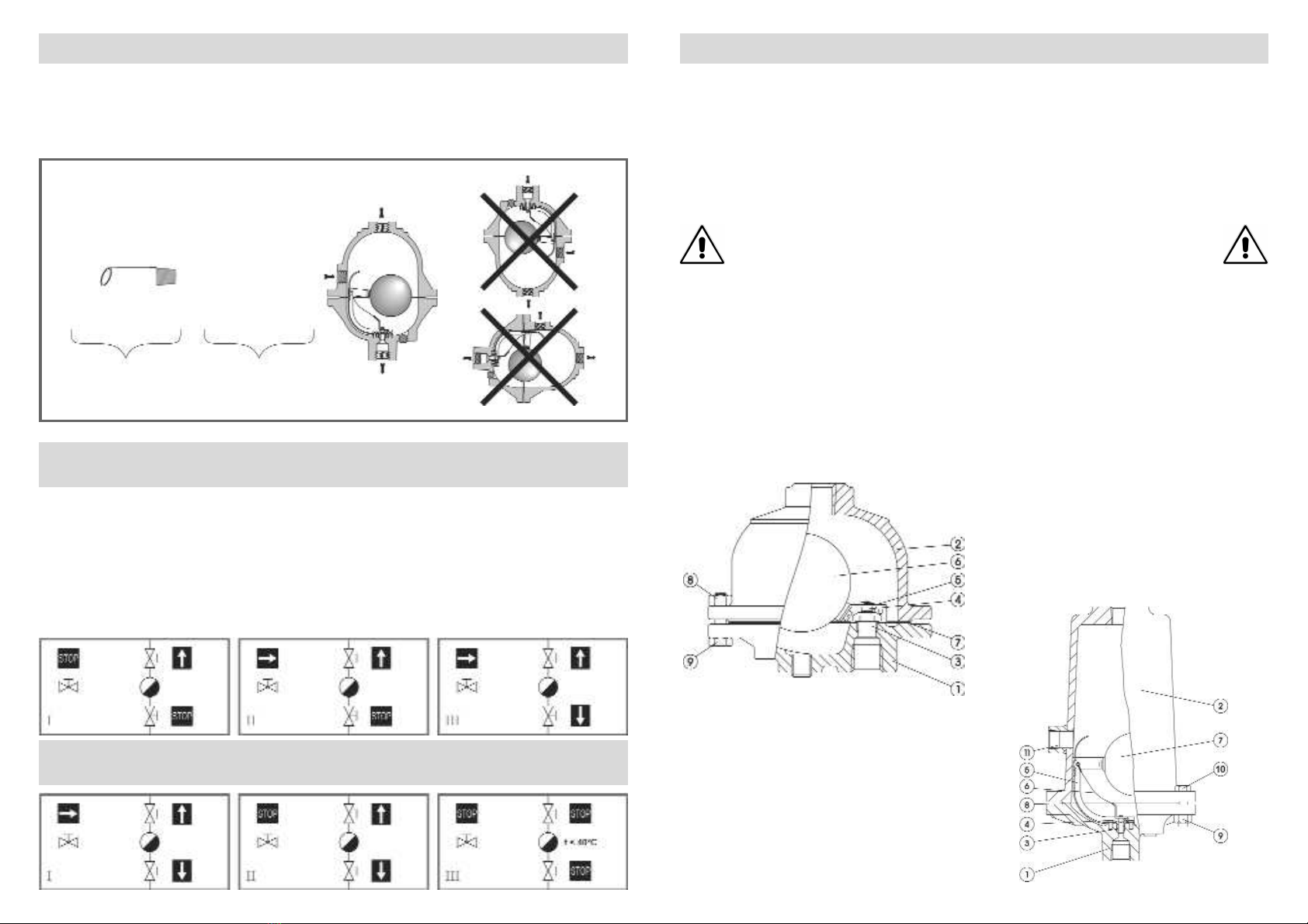
I. 21: Internals Maintenance:
- Remove the complete drainer from the line;
- Unscrew bolts (9) and nuts (8) and remove the cap (1) with the operating
mechanism fixed on it;
- Unscrew the seat (3) and replace the complete Mechanism Less Float (3,
4, 5);
- Screw back the seat (3) and make sure that the lever (5) is aligned in the
axis of the cap (1). A clearance of 0,1 mm should be left in order to allow
the lever (5) to move horizontally;
- Replace the float (6) if necessary;
- Replace gasket (7);
- Put the cap (1) back on the body (2) and screw bolts (9) and nuts (8).
II. 71: Internals Maintenance:
- Remove the complete drainer from the line;
-Unscrew bolts (10) and nuts (9) and remove the cap (1) with the
operating mechanism fixed on it;
- Unscrew the 2 mechanism bolts and replace the complete Mechanism
Less Float (3, 4, 5, 6);
- Screw back the 2 mechanism bolts and make sure that the valve (4) is
closing tightly in the centrum of the seat (3);
- Replace the float (7) if necessary;
- Replace gasket (8);
- Put the cap (1) back on the body (2) and screw bolts (10) and
nuts (9).
I. 21: Binnenwerk vervangen:
- Verwijder de gehele vloeistoflozer uit de leiding;
- Verwijder bouten (9) en moeren (8) en verwijder de kap (1) inclusief het
mechanisme;
- Draai zitting (3) los en vervang het complete mechanisme zonder vlotter
(3, 4, 5);
- Monteer de zitting (3) terug en overtuig Uzelf ervan dat de hefboom (5)
is uitgelijnd in de as van het deksel (1). 0,1 mm vrije ruimte moet aanwezig
om de hefboom (5) horizontaal te laten bewegen.
- Vervang de vlotter (6) indien nodig;
- Vervang pakking (7);
- Plaats het deksel (1) terug op het huis (2) en draai bouten (9) en moeren
(8) weer vast.
II. 71: Binnenwerk vervangen:
- Verwijder de gehele vloeistoflozer uit de leiding;
- Verwijder bouten (10) en moeren (9) en verwijder de kap (1) inclusief het
mechanisme;
- Draai de 2 boutjes van het klepmechanisme los en vervang het complete
mechanisme zonder vlotter (3, 4, 5, 8);
- Draai de 2 boutjes op het mechanisme weer vast en overtuig Uzelf ervan
dat de klep (4) goed in het midden van de zitting (3) afsluit;
- Vervang de vlotter (7) indien nodig;
- Vervang pakking (8);
- Plaats het deksel (1) terug op het huis (2) en draai bouten (10)
en moeren (9) weer vast.
I. 21. Mantenimiento de las piezas internas:
- Retire el drenador completo de la línea;
- Afloje los pernos (9) y las tuercas (8) y desmonte la tapa (1) con el
mecanismo de funcionamiento sujeto a ella;
- Desajuste el asiento (3) y cambie el mecanismo sin boya completo (3, 4,
5);
- Vuelva a ajustar el asiento (3) y asegúrese de que la palanca (5) está
alineada en el eje de la tapa (1). Debe quedar un espacio libre de 0,1 mm
para que la palanca (5) se pueda mover horizontalmente.
- Cambie la boya (6) si es necesario;
- Cambie la junta (7);
- Vuelva a colocar la tapa (1) en el cuerpo (2) y ajuste los pernos (9) y las
tuercas (8).
I. 71. Mantenimiento de las piezas internas:
- Retire el drenador completo de la línea;
- Afloje los pernos (10) y las tuercas (9) y desmonte la tapa (1) con el
mecanismo de funcionamiento sujeto a ella;
- Afloje los dos pernos del mecanismo y cambie el mecanismo sin boya
completo (3, 4, 5, 6);
- Vuelva a ajustar los dos pernos del mecanismo y asegúrese de que la
válvula (4) cierra firmemente en el centro del asiento (3);
- Cambie la boya (7) si es necesario;
- Cambie la junta (8);
- Vuelva a colocar la tapa (1) en el cuerpo (2) y ajuste los pernos
(10) y las tuercas (9).