ARRI ERM-2400 User manual

External Radio Modules for LCS
ERM-2400 SUP2.3
Date 06.04.2020
USER MANUAL

Imprint
Copyright © 2020 Arnold & Richter Cine Technik GmbH & Co. Betriebs KG.
All rights reserved.
No parts of this document may be reproduced without prior written consent of Arnold &
Richter Cine Technik GmbH & Co. Betriebs KG.
Specifications are subject to change without NOTE.
Errors, omissions, and modifications excepted.
ARRI, ALEXA, AMIRA, LDS and LENS DATA SYSTEM are trademarks or registered
trademarks of Arnold & Richter Cine Technik GmbH & Co. Betriebs KG.
All other brands or products are trademarks or registered trademarks of their respective
holders and should be treated as such.
Original version.
For further assistance:
Arnold & Richter Cine Technik GmbH & Co. Betriebs KG
Herbert-Bayer-Str. 10
80807 München
Germany
www.arri.com
Document revision history
Version Release SUP Date
1.0 F07357 2.3 06.04.2020
Scope
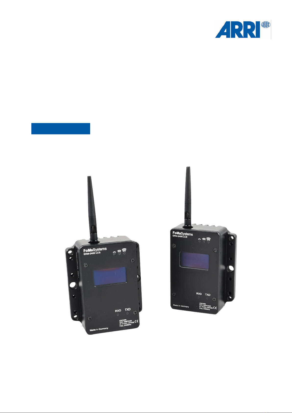
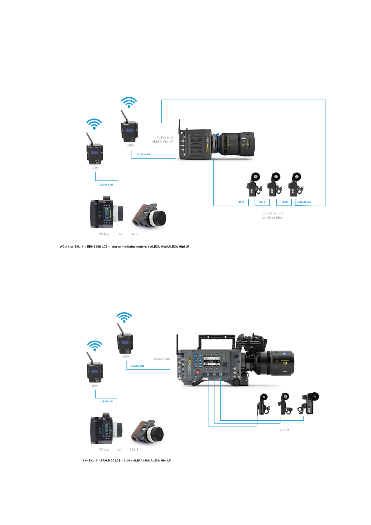
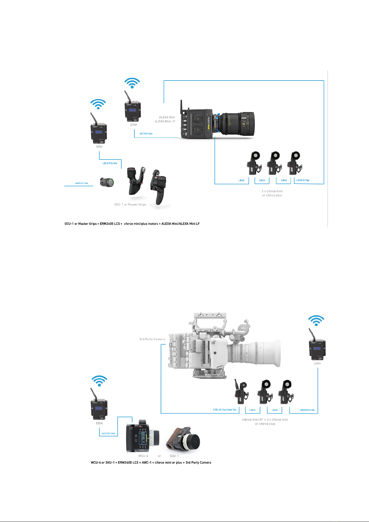
This document describes the components and respective the setups of the
ERM-2400 Ext. Radio Module 2.4GHz RXD-TXD, LCS, Basic Set K2.0037120
by FoMa Systems.
Disclaimer
Before using the products described in this manual, be sure to read and understand all the
respective instructions.
Otherwise the customer must contact ARRI before using the product.
While ARRI endeavours to enhance the quality, reliability and safety of their products, customers
agree and acknowledge that the possibility of defects thereof cannot be eliminated entirely.
To minimize the risk of damage to property or injury (including death) to persons arising from defects
in the products, customers must incorporate sufficient safety measures in their work with the system
and heed the stated conditions of use.
ARRI or its subsidiaries do not assume any responsibility for losses incurred due to improper handling
or configuration of the product or other system components.
ARRI assumes no responsibility for any errors that may appear in this document.
The information is subject to change without NOTICE.
For product specification changes after this manual was published, refer to the latest published
ARRI data sheets or release notes, etc., for the most up-to-date specifications.
Not all products and/or types are available in every country. Please check with an ARRI sales
representative for availability and additional information.
Neither ARRI nor its subsidiaries assume any liability for infringement of patents, copyrights or other
intellectual property rights of third parties by or arising from the use of ARRI products or any other
liability arising from the use of such products. No license, express, implied or otherwise, is granted
under any patents, copyrights or other intellectual property right of ARRI or others.
ARRI or its subsidiaries expressly exclude any liability, warranty, demand or other obligation for any
claim, representation, cause, action, or whatsoever, express or implied, whether in contract or not,
including negligence, or incorporated in terms and conditions, whether by statue, law or otherwise.
In no event shall ARRI or its subsidiaries be liable for or have a remedy for recovery of any special,
direct, indirect, incidental, or consequential damages, including, but not limited to lost profits, lost
savings, lost revenues or economic loss of any kind or for any claim by a third party, downtime,
good-will, damage to or replacement of equipment or property, any cost or recovery of any material
or goods associated with the assembly or use of our products, or any other damages or injury of the
persons and so on or under any other legal theory. In the event that one or all of the foregoing clauses
are not allowed by applicable law, the fullest extent permissible clauses by applicable law are
validated.
ERM for LCS
SUP2.3
of215
Imprint

Table of contents
ERM for LCS
SUP2.3
of315
1
For your safety…………………………………………………………………………..
4
2
Functions …………………………………………………………………………………
5
3
Introduction …..…………………………….…………………………………………….
6
3.1
How It Works ……………………………………………………………….……………
6
3.2
Compatibility…….………………….…………………………………………………….
6
3.3
Handling Transmitter / Receiver ……………………………………………………….
6
3.4
The basic set ……………………………………………………………………..……..
7
3.5
Recommended and required optional extension cables ……………………………
7
3.6
Additional LBUS extensions cables …………………………………………………..
7
3.7
LBUS power cables .…..………………………………………………………….…….
7
3.8
Spare cables …………………………………………………………………………….
7
4
Connecting the ERM via LCS, Ext. and LBUS ..…………………………………….
8
4.1
WCU-4 / SXU-1 ………………………………………………………………………….
8
4.2
ALEXA Plus ……………………………………………………………………………
8
4.3
Master Grip to ALEXA Mini, ALEXA Mini LF and AMIRA …..……………………….
9
5
Third Party Cameras ……………………………………………………………………
9
5.1
WCU-4 / SXU-1 / cforce mini RF motor ………………………………………………
9
5.2
WCU-4 / SXU-1 / AMC-1 / cforce mini motors ..……………………………………..
10
6
Connecting the DEW-1 & DEH-1 via LBUS and ERM with the SRH RCP ……….
10
7
Appendix …………………………………………………………………….…………..
11
Table of Contents

1 For your safety
1.1
How to use this manual
All directions are given from a camera operator's point of view. For example, camera-right
side refers to the right side of the camera when standing behind the camera and operating
it in a normal fashion.
1.2
Strengthen your knowledge and get trained
The ARRI Academy courses provide unrivaled insights into the full possibilities of working
with ARRI camera systems, camera stabilizer systems, lenses, lights and accessories.
To learn more, please visit http://arri.com/academy.
1.3
Risk levels and alert symbols
Safety warnings, safety alert symbols, and signal words in these instructions indicate
different risk levels:
ERM for LCS
SUP2.3
of415
For your safety
The ERM for LCS system and related products should only be used by
experienced and trained operators.
This product is NOT intended for inexperienced users and should not be
used without reading the manual or additional training.
ARRI recommends that all users read the manual in its entirety prior to use.
Warning
NOTICE
The product is solely and exclusively available for commercial customers and
shall be used by skilled personnel only.
Every user should be trained according to ARRI guidelines. Use the product only
for the purpose described in this document. Always follow the valid instructions
and system requirements for all equipment involved.
DANGER indicates an imminent hazardous situation which, if not avoided,
will result in death or serious injury.
WARNING indicates a potentially hazardous situation which, if not avoided, may
result in death or serious injury.
CAUTION indicates a potentially hazardous situation which, if not avoided, may
result in minor or moderate injury.
NOTICE
NOTE explains practices not related to physical injury. No safety alert symbol
appears with this signal word.
NOTE
Provides additional information to clarify or simplify a procedure.
DANGER
Warning
CAUTION

2 Functions
2.1
Functions front
2.2
Functions back
ERM for LCS
SUP2.3
of515
Functions
FS CAN Bus
Signal Strength
Display
Rubber Duck Antenna
USB Port
Power In
LEMO 0B 2pin
RXD / TXD Status
M4 thread
RMB-2 / RMB-3
mounting threads
3/8“ thread / RMB-2
mounting thread
1/4“ thread

3 Introduction
3.1
How It Works
An ERM-2400 LCS set of radio modules basically extends an LCS,LBUS, EXT (CAN bus)
cable connection over air. As such, it can connect ARRI and cmotion hand units to cameras
and motor controllers and they behave as if they were hard-wired, but with an exceptionally
great wireless range.
3.2
Compatibility
The ERM-2400 LCS module is compatible with equipment supporting LCS, EXT and LBUS
protocols.
A pair of ERM-2400 LCS modules can replace a cabled connection between two devices,
for example:
• WCU-4 or SXU-1 and ALEXA Plus camera (LCS socket)
• WCU-4 or SXU-1 and ALEXA Mini camera (EXT socket)
• WCU-4 or SXU-1 and ALEXA Mini LF camera (EXT socket)
• WCU-4 or SXU-1 and UMC-4 (LCS socket)
• Master Grip or OCU-1 and cforce motor
• cmotion cPRO hand unit and cforce motor
• ARRI Wheels DRW-1 and Digital Encoder Head DEH-1
3.3
Handling Transmitter / Receiver
ERM-2400 LCS are supplied as an already paired set of two radio modules, including all
necessary cables. Once connected to handset and camera device, they will power up and
connect automatically.
The modules can be used both as transmitters and receivers.
Pre-configured pairs can be identified through a matching number code at the back of
each device.
ERM for LCS
SUP2.3
of615
NOTICE
The external radio module ERM-2400 LCS has been developed exclusively
for use with the ARRI ECS products and workflows.
Any other use is not recommended and may damage the modules.
NOTICE
Avoid mixing individual modules with other sets of paired ERMs.
Setup
NOTICE
ERM-2400 for LCS and ERM-2400 for SRH are NOT compatible with one
another.
NOTICE
The OCU-1 / Master Grips override function is not supported with ERM-2400
LCS, because override is not possible in hardwired mode neither.

3.4
Thebasicset
ERM-2400 Ext. Radio Module 2.4GHz RXD-TXD, LCS, Basic Set K2.007120
Includes:
2 x ERM-2400 Ext. Radio Module 2.4 GHz RXD-TXD LCS (incl. antennas)
2 x ERM LCS to FS CAN Bus Adapter Cable, 0.2m/0.65ft
2 x ERM LBUS to FS CAN Bus Adapter Cable, 0.2m/0.65ft
1 x ERM EXT to FS CAN Bus Adapter Cable, 0.2m/0.65ft
1 x ERM D-Tap Power Cable, 0B Lemo 2pin to D-Tap, 1m/3.2ft
3.5
Recommended and required optional extension cables
SRH FS CAN Bus Cable, 1m/3.2ft K2.0033762
SRH FS CAN Bus Cable, 10m/32.8ft K2.0019302
SRH FS CAN Bus Cable, 25m/82ft K2.0019301
3.6
Additional LBUS extensions cables
Cable LBUS - LBUS (0.8m/2.6ft) K2.0006752
Cable LBUS - LBUS (1.5m/5ft) K2.0006753
Cable LBUS - LBUS (3m/10ft) K2.0006754
Cable LBUS - LBUS (6m/20ft) K2.0006755
Cable LBUS - LBUS (15m/49ft) K2.0006756
3.7
LBUS power cables
Cable LBUS - D-Tap (0.8m/2.6ft) K2.0006758
Cable LBUS - D-Tap (1.2m/4ft) K2.0006757
Cable LBUS - XLR (4p) (0.8m/2.6ft) K2.0006760
3.7
Spare cables
ERM LCS to FS CAN Bus Adapter Cable, 0.2m/0.65ft K2.0036900
ERM LBUS to FS CAN Bus Adapter Cable, 0.2m/0.65ft K2.0036903
ERM EXT to FS CAN Bus Adapter Cable, 0.2m/0.65ft K2.0036901
ERM D-Tap Power Cable, 0B Lemo 2pin to D-Tap, 1m/3.2ft K2.0036902
ERM for LCS
SUP2.3
of715
To exclude any health risk, the minimum distance between
the ERM transmitter and the operator must be at least 1 m.
CAUTION
NOTICE
The basic set is only supplied with adapter cables.
However, FS CAN bus and / or LBUS extension cables are required for use.
These extension cables have to be ordered separately!
Setup

4 Connecting the ERM via LCS, Ext. and LBUS
4.1
WCU-4 / SXU-1
4.2
ALEXA Plus
ERM for LCS
SUP2.3
of815
Connecting
ERM LCS to FS CAN Bus Adapter
Cable, 0.2m/0.65ft K2.0036900
ERM LCS to FS CAN Bus Adapter Cable,
0.2m/0.65ft K2.0036900
ERM LCS to FS CAN Bus Adapter
Cable, 0.2m/0.65ft K2.0036900
Required optional extension cables
SRH FS CAN Bus Cable, 1m/3.2ft K2.0033762
SRH FS CAN Bus Cable, 10m/32.8ft K2.0019302
SRH FS CAN Bus Cable, 25m/82ft K2.0019301
ERM EXT to FS CAN Bus Adapter Cable,
0.2m/0.65ft K2.0036901
Required optional extension cables
SRH FS CAN Bus Cable, 1m/3.2ft K2.0033762
SRH FS CAN Bus Cable, 10m/32.8ft K2.0019302
SRH FS CAN Bus Cable, 25m/82ft K2.0019301

4.3
Master Grip to ALEXA Mini, ALEXA Mini LF and AMIRA
5.0 Third Party Cameras
5.1
WCU-4 / SXU-1 / cforce mini RF motor
ERM for LCS
SUP2.3
of915
Connecting
ERM EXT to FS CAN Bus Adapter Cable,
0.2m/0.65ft K2.0036901
ERM LBUS to FS CAN Bus Adapter Cable,
0.2m/0.65f K2.0036903
Cable LBUS - D-Tap
0.8m/2.6ft K2.0006758
Required optional extension cables
SRH FS CAN Bus Cable, 1m/3.2ft K2.0033762
SRH FS CAN Bus Cable, 10m/32.8ft K2.0019302
SRH FS CAN Bus Cable, 25m/82ft K2.0019301
Cable LBUS - D-Tap
0.8m/2.6ft K2.0006758
ERM LBUS to FS CAN Bus
Adapter Cable, 0.2m/0.65f
K2.0036903
ERM LCS to FS CAN Bus Adapter
Cable, 0.2m/0.65ft K2.0036900
Required optional extension cables
SRH FS CAN Bus Cable, 1m/3.2ft K2.0033762
SRH FS CAN Bus Cable, 10m/32.8ft K2.0019302
SRH FS CAN Bus Cable, 25m/82ft K2.0019301

5.2
WCU-4 / SXU-1 / AMC-1 / cforce mini motors
6 Connecting the DEW-1 & DEH-1 via LBUS and ERM
with the SRH remote control panel
ERM for LCS
SUP2.3
of10 15
Connecting
Cable LBUS - D-Tap
0.8m/2.6ft K2.0006758
ERM LCS to FS CAN Bus Adapter
Cable, 0.2m/0.65ft K2.0036900
Required optional extension cables
SRH FS CAN Bus Cable, 1m/3.2ft K2.0033762
SRH FS CAN Bus Cable, 10m/32.8ft K2.0019302
SRH FS CAN Bus Cable, 25m/82ft K2.0019301
ERM LCS to FS CAN Bus Adapter
Cable, 0.2m/0.65ft K2.0036900
SRH RCP ext. Power Supply Set Gold-Mount
K0.0024195
SRH RCP ext. Power Supply Set V-Mount
K0.0024196
12V Battery Power Cable, D-Tab, 4pin XLR
K2.0021422
Required optional extension cables
SRH FS CAN Bus Cable, 1m/3.2ft K2.0033762
SRH FS CAN Bus Cable, 10m/32.8ft K2.0019302
SRH FS CAN Bus Cable, 25m/82ft K2.0019301
Cable LBUS - D-Tap
0.8m/2.6ft K2.0006758

7 Technical Data
7.1
Pinout
7.2
ERM-2400 Specifications Electrical/General
Supported Frequency 2.400 - 2.4835 GHz
Spreading Method Frequency Hopping, DTS
7.3
ERM-900 Specifications Electrical/General
Supported Frequency 902 - 928 MHz
Spreading Method Frequency Hopping, DTS
7.4
Dimensions without antenna ERM-2400 / ERM-900
Length 11 cm / 4.33“
Width 9 cm / 3,54“
Hight 4 cm / 1,57“
7.5
Weight 380 gr / 0.83 lb
7.6
Operating Temperature -40oC / -40o to 85oC / 185oF
Humidity 5% to 95% non-condensing
ERM for LCS
SUP2.3
of11 15
Appendix
FFCAN
Löseie Bchse
GND
CAN L
CAN H
V
Fischer DBP A
RCDaa PLC
RX DATA IN FROM WHEELS
N C
TX DATA OUT TO WHEELS
GND
Löseie Bchse LEMO ECPSCLN
RS V
GND
V
FISCHER DBP A
Löseie Bchse
AUX Pr V
Löseie Bchse
GND
V OUT
LEMO ECGBCLN
FSCAN
Löseie Bchse
GND
CAN L
CAN H
V OUT
Fischer DGP A
REMOTE Connecors V
AUX Pr V
Löseie Bchse
GND
V OUT
LEMO ECGBCLN

7.7
Dimensional Drawings
ERM for LCS
SUP2.3
of12 15
Appendix

8 Declarations of Conformity
8.1
Approval Information
The products offered by ARRI are approved for use in a number of countries. Product-
specific information on approval can be found in the respective operating instruction
manuals. Import and use in countries other than those mentioned in the respective
operating instructions may be subject to legal, regulatory, or official requirements and
regulations. Before the products are imported into these countries or used in these
countries, compliance with the existing legal, regulatory, and administrative requirements
and regulations must be ensured. It is the importer's or the user's responsibility, prior
to importation or use, to inform themselves of the applicable legal, regulatory, and
administrative requirements and regulations and to ensure compliance with these
requirements and regulations, including applying for and obtaining any necessary
approvals or registrations.
As far as reasonable and legally possible, ARRI will support requests in relation to such
applications by providing technical documents or declarations. As an importer or user,
you confirm that you are familiar with and comply with the legal, regulatory, and
administrative requirements and regulations that apply in the countries to which you ship
or use the products. You further confirm that you will arrange for any necessary
registrations, enrolments, or authorisations that are required in such countries.
You release ARRI from all obligations resulting from any legislative, regulatory, or
administrative requirements regarding import or use of the products, except in countries
where ARRI has obtained a registration or certification. You agree to indemnify, defend,
and hold ARRI harmless from any and all claims, damages, losses, liabilities, costs, and
expenses (including reasonable fees of attorneys and other professionals) that may arise
out of a demand on ARRI in connection with your obligations mentioned above.
ERM for LCS
SUP2.3
of13 15
Appendix

8.2
CE
ERM for LCS
SUP2.3
of14 15
Appendix
Declaration of Conformity
Product Type
External Radiomodule
Brand Name
FoMaSystems
Product Name
FoMaSystems ERM-P2400
Address
FoMa Systems GmbH
Oskar-Sembach-Ring 11
D-91207 Lauf
The product complies which the requirements of the following European directives:
2014/53/EU
DIRECTIVE 2014/53/EU OF THE EUROPEAN PARLIAMENT AND OF
THE COUNCIL on the harmonisation of the laws of the Member States
relating to the making available on the market of radio equipment and
repealing Directive 1999/5/EC
Compliance was proved by the application of the following standards:
EN 62368-1:2014 + AC:2015
Draft ETSI EN 301 489-1:V2.2.0 (2017-03)
Draft ETSI EN 301 489-17:V3.2.0 (2017-03)
EN 300 328 V2.1.1
2011/65/EU
Directive of the European Parliament and of the council on the
restriction of the use certain hazardous substances in electrical and
electronic equipment.
Compliance was proved by the application of the following standards:
EN 50581 : 2012
Year of the first marking: 2019

8.3
FCC Statement / IC Statement
USA
ERM-2400 contains: FCCID: NS9P2400
The ERM-2400 will be shipped with readjusted 0.1Watt transmission power to be complaint
in all addressed markets.
§15.19(a)
Operation is subject to the following two conditions:
(1) This device may not cause harmful interference, and
(2) this device must accept any interference received, including interference that may
cause undesired operation.
Part 15 Clause 15.21
Changes or modifications not expressly approved by the party responsible for compliance
could void the user's authority to operate the equipment.
Canada
ERM-2400 contains: IC 3143A-14P2400
This device complies with Industry Canada’s
licence-exempt RSSs.
Operation is subject to the following two conditions:
(1) This device may not cause interference; and
(2) This device must accept any interference, including interference that may cause
undesired operation of the device.
Le présent appareil est conforme aux CNR d’Industrie Canada applicables aux appareils
radio exempts de licence. L’exploitation est autorisée aux deux conditions suivantes :
1) l’appareil ne doit pas produire de brouillage;
2) l’appareil doit accepter tout brouillage radioélectrique subi, même si le brouillage est
susceptible d’en compromettre le fonctionnement.
84
Australia / New Zealand
8.5
Japan
ERM for LCS
SUP2.3
of15 15
NOTICE
For USA and Canada the transmission power can be changed locally by the
ARRI service to 1Watt transmission power.
NOTICE
Make sure that you select the proper area you are operating the device in.
All available region settings comply with Part 15 of the FCC rules.
!
International Declarations
17
TÜV SÜD Product Service GmbH
Äußere Frühlingstraße 45
94315 Straubing
Germany
Phone: +49 9421 5522-0
Fax: +49 9421 5522-99
Web: www.tuev-sued.de
Test Report No. TR-25880-63178-03 (Edition 01) Page 3 of 63
Test Item description .................................... : External Radiomodule
Trade Mark ................................................... : FoMa
Manufacturer ................................................. : FoMa Systems GmbH
Model/Type reference .................................. : ERM-P2400
Ratings ......................................................... : 14.4 - 36 Vdc, max. 4A
Testing procedure and testing location:
Testing Laboratory: TÜV SÜD Product Service GmbH
Testing location/ address ...........................: Äußere Frühlingstraße 45, D-94315 Straubing, Germany
Tested by (name + signature) .............:
Alexander Fischer
Approved by (name + signature) .........:
Stefan Weiherer
© Microhard Systems Inc. Confidential 4
Ia Ue Ifa (ced)
P2400 Rea Reee
WARNING:
T FCC/IC RF , 25
. T ,
. T - .
WARNING:
O : (1) , (2)
.
WARNING:
C M S I. ’ . T
UFL R P SMA A A OEM ,
- - . A
FCC S 15.203 ( ) S 15.247 ().
WARNING:
MAIMUM EIRP
FCC Regai a 36 dB eiae iica adiaed e (EIRP). Theefe, he f he aied e (i dB),
he cabig ad he aea gai ca eceed 36 dB.
WARNING:
EQUIPMENT LABELING
The FCC ad IC be deed he de f he adi de. D NOT e he Maeig Nae f he dc b he Mde
diigih he Ceificai Nbe. Thi deice ha bee da aed. The aface, dc ae, ad FCC ad Id
Caada ideifie f hi dc aea he ide abe f he ed-e eie.
WARNING:
T I C’ - RSS. O :
(1) T ; (2) T ,
.
SAMPLE LABEL REQUIREMENT f Mde: 2400: Jaa MIC 2400:
Ca:
FCCID: NS9P2400 IC: 3143A-14P2400
This device complies with Part 15 of the FCC Rules.
Operation is subject to the following two conditions:
(1) this device may not cause harmful interference, and (2)
this device must accept any interference received
including interference that may cause undesired operation.
© Microhard Systems Inc. Confidential 5
Ia Ue Ifai (cied)
Cai:
FCCID: NS9P2400 IC: 3143A-P2400
Cet appareil est conforme à la partie 15 des rgles
de la FCC. Son fonctionnement est soumis aux
deux conditions suivantes : ( 1 ) ce dispositif ne doit
pas causer d'interfrences nuisibles et ( 2) cet
appareil doit accepter toute interfrence reçue,
incluant les interfrences qui peuvent provoquer un
fonctionnement indsirable .
WARNING:
Pour satisfaire aux exigences de la FCC/IC d'exposition RF pour la base et mobiles sur une distance de sparation de 25 cm ou plus doit
tre maintenue entre l'antenne de cet appareil et des personnes lors de fonctionnement du dispositif. Pour assurer la conformit des
oprations au plus prs que cette distance n'est pas recommande. L'antenne utilise pour ce transmetteur ne doit pas tre co-localiss en
conjonction avec toute autre antenne ou transmetteur.
WARNING:
Son fonctionnement est soumis aux deux conditions suivantes : ( 1 ) ce dispositif ne doit pas causer d'interfrences nuisibles et ( 2) cet appareil
doit accepter toute interfrence reçue, incluant les interfrences qui peuvent provoquer un fonctionnement indsirable .
WARNING:
Les changements ou modifications non expressment approuvs par Microhard Systems Inc. pourraient annuler l'autorit de l'utilisateur à
utiliser l'quipement . Ce dispositif a t test avec MCX et connecteurs SMA à polarit inverse sur les antennes rpertories à l'annexe A
Lorsqu'il est intgr dans les produits OEM , antennes fixes ncessitent une installation empchant les utilisateurs finaux de les remplacer par
des antennes non approuves . Antennes ne figurant pas dans les tableaux doivent tre tests pour se conformer à la Section 15.203
(connecteurs d'antenne uniques ) et à la Section 15.247 ( missions ) .
WARNING:
MAXIMUM PIRE
Rglement FCC permettent jusqu'à 36 dBm puissance isotrope rayonne quivalente ( PIRE) . Par consquent, la somme de la puissance
mise ( en dBm ), la perte de câblage et le gain d'antenne ne peut pas dpasser 36 dBm.
WARNING:
ÉQUIPEMENT DE MARQUAGE
Les numros FCC et IC dpendent du modle du module radio . Ne pas utiliser le nom marketing du produit, mais le modle de distinguer les
numros Certifications . Ce dispositif a t approuv de façon modulaire . Le fabricant , nom du produit, et les identificateurs de la FCC et
d'Industrie Canada de ce produit doivent figurer sur l'tiquette à l'extrieur de l'quipement de l'utilisateur final .
WARNING:
Cet appareil est conforme aux CNR exempts de licence d'Industrie Canada . Son fonctionnement est soumis aux deux conditions suivantes :
( 1 ) Ce dispositif ne peut causer des interfrences ; et ( 2 ) Ce dispositif doit accepter toute interfrence , y compris les interfrences qui
peuvent causer un mauvais fonctionnement de l'appareil.
L'EXEMPLE D'TIQUETTE:
Appendix
Other manuals for ERM-2400
1
This manual suits for next models
1
Table of contents
Other ARRI Control Unit manuals
Popular Control Unit manuals by other brands

MicroComm DXL
MicroComm DXL TMM-640 installation instructions

Allen-Bradley
Allen-Bradley 1756 Series installation instructions

ACM
ACM MINI-RX1 quick start guide

SMC Networks
SMC Networks VQ2000 Series Installation and maintenance manual

Velleman
Velleman Whadda WPI304 user manual

Pilz
Pilz PIT es Set10u-5ns (AIDA) basic operating manual