P/N 80-9150-0064-010 Rev A
An ASSA ABLOY Group brand
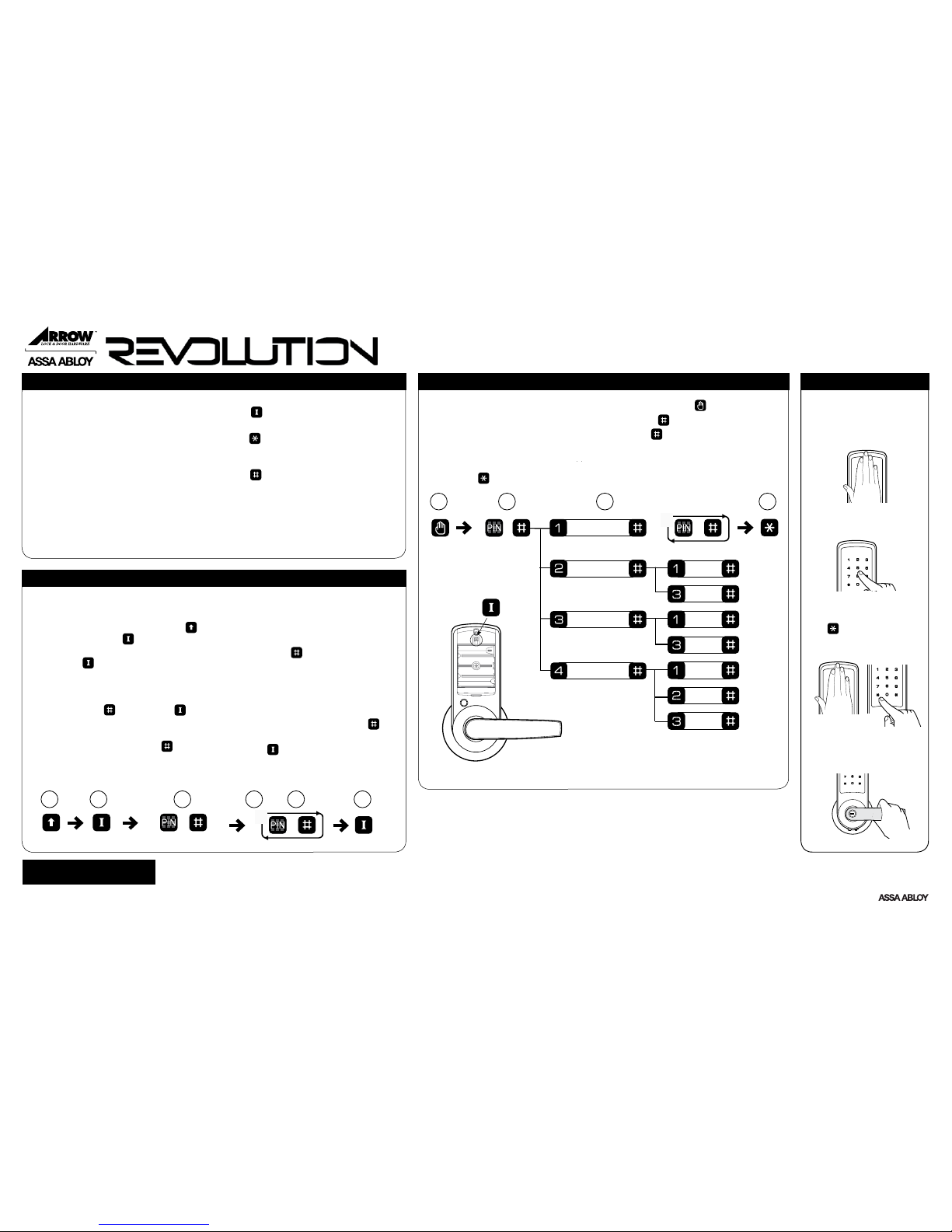
SU
1 - 8
Feature Programming Through Menu Mode Using the Supervisor Code
S
Enable
Disable
English
Spanish
French
Enable
U
1 - 8
Register User Code
Silent Mode
Passage Mode
Disable
Language Mode
1. Touch the screen with the palm of your hand or fingers to acitivate .
2. Enter the 4-12 digit Supervisor PIN code followed by the key.
Lock Response: “Menu mode, enter number, press the key to continue.”
3. Enter digit corresponding to the function to be performed.
Follow the verbal commands.
4. Press the key to complete the process and conclude the programming session.
1 2
This Quickstart Guide is for programming in
Easy Mode. For more details and Advanced Mode
programming, please refer to the complete
Programming Instructions.
• For proper security, the Supervisor or Mas-
ter PIN code should be changed as soon as
the lock is installed.
• The factory default setting is Easy Mode. In
Easy Mode, one Supervisor and eight User
PIN code locations are available.
• In Easy Mode, when there are any additions
or changes to codes, all existing PIN codes
ARE DELETED and must be re-entered.
Introduction Open Door With PIN Code
1. Touch the screen with
the palm of your hand or
fingers to activate.
2. Enter PIN code.
3. Palm or touch the
key to confirm the
selection.
4. Turn lever to
open door.
PIN Code Programming Instructions (Easy Mode) Using the “ I ” Button
• PIN codes can be 4 to 12 digits in length.
• The button is located under the
battery cover above the batteries.
• The key is used to enter or accept an
entry, and also to conclude a programming
session.
• The key is used either to enter or to
continue additional steps in a programming
sequence.
• The factory default PIN code in Easy Mode:
Supervisor: 1 2 3 4 5 6 7 8 9 0
• The factory default PIN code in Advanced
Mode: Master: 1 2 3 4 5 6
1. Unscrew battery cover hex screw using
tool provided. Slide battery cover up
and off to reveal the button located
above the batteries.
2. Press the button once.
Lock response: “Register User code.
Enter one Supervisor then up to 8 users.
Enter a 4 to 12 digit PIN code, each
followed by the key. Press the
button to complete.”
3. Enter the new Supervisor PIN code
(4 to 12 digits) followed by the key.
Lock Response: Sounds a tone for each
PIN code digit with digits flashing in the
sequence entered to confirm the entry.
Chime signals when playback is complete.
4. Enter the first User PIN code (4 to 12 digits)
followed by the key.
Lock Response: Sounds a tone for each
PIN code digit with digits flashing in the
sequence entered to confirm the entry.
Chime signals when playback is complete.
5. Continue to enter additional User PIN codes
(4 to 12 digits each) followed by the key.
Up to eight User PIN codes can be entered.
6. Press the button to complete the
process after the last playback sequence.
Lock Response: “Registered.”
Note: Be sure PIN codes are recorded. Entering any new code erases the existing codes.
IButton
3 4
1 2 3 4 5 6
EASY MODE PROGRAMMING INSTRUCTIONS
Quickstart Guide
For Technical Assistance call Arrow:
1-800-221-6529.