Siegenia KFV AS3500 User manual

KFV
DEUTSCH ENGLISH FRANÇAIS ESPAÑOL ITALIANO NEDERLANDS ČESKÝ POLSKI РУССКИЙ
Assembly instructions: AS3500
Multi-point lock
Window systems
Door systems
Comfort systems
ASSEMBLY INSTRUCTIONS


Contents
1. Introduction............................................................................................................................................................. 4
1.1 Target group of this documentation........................................................................................................... 4
1.2 Intended use ............................................................................................................................................. 4
1.2.1 Installation location ..................................................................................................................... 4
1.2.2 Locking part and hardware ......................................................................................................... 4
1.2.3 Transport..................................................................................................................................... 4
1.3 Improper use............................................................................................................................................. 4
1.4 Care and service instructions..................................................................................................................... 5
1.5 Installation conditions and requirements.................................................................................................... 5
1.5.4 Dimensions .................................................................................................................................. 5
1.6 Explanation of symbols ............................................................................................................................. 6
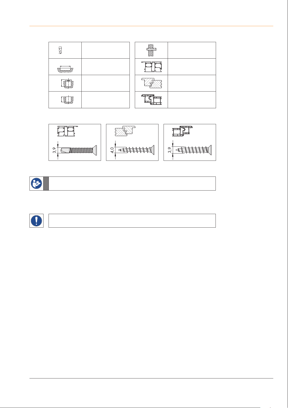
1.7 Screw recommendation............................................................................................................................. 6
1.8 Instructions and symbols ........................................................................................................................... 6
1.9 Component dimensions ............................................................................................................................. 7
2. Installation .............................................................................................................................................................. 9
2.1 Cutting the door leaf ................................................................................................................................. 9
2.2 Pre-drilling the operating lever (optional)................................................................................................ 10
2.3 Repositioning the latch (optional)............................................................................................................ 11
2.4 Installing the A-opener (optional)............................................................................................................ 12
2.5 Installing the door arrester or daytime release (optional) ....................................................................... 13
2.6 Screwing on the multi-point lock .............................................................................................................. 15
2.7 Cutting the door frame ............................................................................................................................ 16
2.8 Installing the magnetic clip...................................................................................................................... 17
2.9 Screwing in the frame parts..................................................................................................................... 18
2.10 Adjusting the frame parts ........................................................................................................................ 19
2.11 Functional test
............................................................................................................................................................................. 20
2.11.1 Checking functionality when the door is open: .......................................................................... 20
2.11.2 Checking functionality when the door is closed ......................................................................... 20
3. Optional additional functions.............................................................................................................................. 21
3.1 Daytime release “TE”.............................................................................................................................. 21
3.2 Safety lock “T3” ..................................................................................................................................... 22
3.3 Safety lock “T4” ..................................................................................................................................... 22
3.4 A-opener................................................................................................................................................. 23
4. Appendix .............................................................................................................................................................. 24
4.1 Use ......................................................................................................................................................... 24
4.2 Liability ................................................................................................................................................... 25
4.2.1 Intended use.............................................................................................................................. 25
4.2.2 Product liability ......................................................................................................................... 25
4.2.3 Exclusion of liability................................................................................................................... 25
312.2019
304.2016 KFV

Introduction
404.2016
KFV
1. Introduction
1.1 Target group of this documentation
This documentation is intended for use by specialists only. All work described in this doc-
ument is to be performed by experienced professionals with training and practice in the
assembly as well as commissioning and maintenance of multi-point locks. Safe and proper
assembly of these locks hinges is not possible without expert knowledge.
1.2 Intended use
1.2.1 Installation location
• The multi-point lock is suitable for installation in single-sash and double-sash doors in
permanent buildings.
• The multi-point lock may only be installed in doors that have been fitted in a technically
sound manner.
• The door design must permit use of the multi-point lock.
1.2.2 Locking part and hardware
• The use of any additional devices to keep the door closed (with the exception of a door
closer) is not permitted. If a door closer is installed, it must not impede operation of the
door by children, the elderly or infirm.
• Repair of the multi-point lock is not permissible. If the multi-point lock is damaged, it must
be replaced by KFV or repaired by a service agent authorised by KFV.
• Only KFV frame parts with Q adjustment may be used.
1.2.3 Transport
• Always transport the multi-point lock in a vertical position, whether uninstalled or installed
in the door leaf.
• Do not place the multi-point lock heavily on the ground when it is unpackaged, as this can
damage the lock.
• Do not carry the door by the lever handle or hardware when transporting it.
• Opening/closing/locking: It must be possible to open and close the door easily.
Aprotruding latch and /or deadbolt must not impede the opening of the door.
17
See note on page 17 for transport when installed in an element.
• The locking elements must always engage freely in the lock striker of the frame parts.
1.3 Improper use
• Do not use for escape doors.
• The multi-point lock is not designed to accommodate changes to its shape or seal which
arise as a result of differences in temperature or changes to the building.
• The multi-point lock must not be used in doors for wet rooms or rooms in which the air
contains aggressive or corrosive components.
• Foreign objects and/or materials which impede or prevent proper use must not be placed
within the opening range, the locking system or the striker plates.
• The multi-point lock must not be interfered with and/or modified.
• Locking elements must not be misused to hold the door open.
• Movable or adjustable locking pieces (e.g. deadbolt, latch) must not be painted over.

Introduction
504.2016 KFV
1.4 Care and service instructions
• Regular annual maintenance should be carried out to ensure that all movable components
are functioning correctly and are lubricated with non-corroding and non-resinous grease.
• Never use cleaning agents that are aggressive or contain solvents, as these may damage
the surface of the components.
• Both the contractor and the user must be trained in the operation and maintenance of the
multi-point lock.
1.5 Installation conditions and requirements
• Local building laws and regulations must be observed before and during door installation
in addition to the following requirements and conditions:
• Observe the milling dimensions
• Position the frame parts according to the specifications, observing the horizontal and
vertical adjustment accurately.
• Before installing the multi-point lock, check the dimensional accuracy of the door and
the door frame. The multi-point lock must not be installed if the door and/or the frame is
warped and/or damaged.
• Install the multi-point lock and accessories according to our assembly instructions. Use the
clamp included in the delivery supplied for assembly.
• Remove any splinters from the lock mortise after milling.
• Once the lock is installed, do not perform mechanical work on the door (such as drilling or
milling). Do not drill into or through the main lock under any circumstances.
• Observe the specified positions and sizes when drilling the holes.
• Follow the hardware manufacturer's instructions when drilling the holes for the operating
handle/hardware.
• Install hardware components and cylinder flush without overtightening the screws or
screwing them in at an angle.
• Fasten handle set by hand only and do not use force when installing the spindle.
• Keep the distance between the secondary sash and frame parts:
For 1-leaf doors: 2 to 6 mm
For 2-leaf doors: 4 to 6 mm
• Operating elements should not impede each other.
• Check that any existing block setting is packed correctly.
• Surface treatment of the door and door frame must take place before the multi-point lock
is installed. A subsequent surface treatment can reduce the functional capacity of the
multi-point lock.
• Use only acid-free neutral-cure sealants to prevent corrosion of components and/or the door.
1.5.4 Dimensions
All measurements are given in mm.

1.6 Explanation of symbols
Milling cutter or drill
diameter Through hole
Groove length for metal profiles
Groove depth from
component for timber profiles
Groove depth from
profile for PVC profiles
1.7 Screw recommendation
1.8 Instructions and symbols
6
See note on page 17 for transport when installed in an element.
This symbol indicates that you should read information given at the relevant point of the
instructions. The number in the grey field beside the symbol defines the page number.
Assembly according to the hardware manufacturer's instructions.
This symbol indicates special features and designates facts that require increased attention.
Introduction
604.2016
KFV

1.9 Component dimensions
Size
ranges A B C G I K
B001 2170 760 730 1020 290 130
B003 2400 760 980 1020 270 130
B039 1700 760 355 952 263 62
B041 1700 760 605 952 13 62
B166 1855 760 730 952 43 62
B253 2170 760 980 952 108 62
B296 2170 760 355 1020 665 130
B298 2170 760 605 1020 415 130
Introduction
All dimensions are in mm 704.2016 KFV

Required accessories
Magnetic clip
For timber profiles
Material number Material description Contents (pieces)
3482034
MAGNETIC TRIGGER-3500-Q-SG-VE2
2
3482035
MAGNETIC TRIGGER-3500-Q-SG-VE10
10
3482036
MAGNETIC TRIGGER-3500-Q-SG-VE100
100
For PVC profiles with steel reinforcement and/or steel frame parts
Material number Material description Contents (pieces)
3489830 MAGNETIC TRIGGER-3500-Q-S1-VE2 2
3489831 MAGNETIC TRIGGER-3500-Q-S1-VE10 10
3489832 MAGNETIC TRIGGER-3500-Q-S1-VE100 100
For PVC profiles with steel reinforcement and/or steel frame parts
Material number Material description Contents (pieces)
3491104 MAGNETIC TRIGGER-3500-V503-SG-VE2 2
3491105 MAGNETIC TRIGGER-3500-V503-SG-VE10 10
3491106 MAGNETIC TRIGGER-3500-V503-SG-VE100 100
Introduction
804.2016
KFV

Required accessories
Daytime release
Material number Material description Contents (pieces)
3485984 ZSK 201-T0-8060/----E 1
or
Door arrester T3
Material number Material description Contents (pieces)
3483983 ZSK 201-T3-8063/VS35-----E 1
3483984 ZSK 201-T3-8063/VS40-----E 1
3483985 ZSK 201-T3-8063/VS45-----E 1
3483986 ZSK 201-T3-8063/VS50-----E 1
3483987 ZSK 201-T3-8063/VS55-----E 1
3483988 ZSK 201-T3-8063/VS60-----E 1
3483989 ZSK 201-T3-8063/VS65-----E 1
3483990 ZSK 201-T3-8063/VS80-----E 1
Either the daytime release or the door arrester can be installed. It is not possible for both to be installed.
Installation
14 04.2016
KFV
A
B

2.8 Installing the magnetic clip
Dimension
variant
B C
B001 760 730
B003 760 980
B039 760 355
B041 760 605
B166 760 730
B253 760 980
B296 760 355
B298 760 605
The multi-point lock could be damaged by automatic triggering of the hook bolts during
transportation of a completely assembled element with the AS3500 multi-point lock
including magnetic triggers. It is therefore recommended:
• to install the magnetic triggers first when the element is installed on site.
or
• prior to transport of the completely assembled element, to use the transport supports
which can be ordered separately (material number 3498292).
Transit support
Material
number
Material
description
Contents
(pieces)
3498292 DZM 498-2300-U-Q/ZM 1
Installation
All dimensions are in mm 1704.2016 KFV

2.11 Functional test
In order to check the functionality, the door and the door frame must be positioned
vertically.
2.11.1 Checking functionality when the door is open:
Check that all fixing screws are secure:
• Use a screwdriver to ensure that all fixing screws are fully screwed in. Screws should not
be screwed in too tightly or over tightened.
Check the lever handle functionality:
• Press the lever handle down fully. The lever handle must return to its original position by itself.
Check the functionality of the latch:
• Press the lever handle down fully. The angle of activation is approx. 30°, as first the hook
bolt and then the main lock latch are retracted to minimise the activation forces. The latch
must retract when the lever handle is pressed. When pressed in, the latch should only
protrude a maximum of 2 mm over the lock faceplate.
• Turn the key in the cylinder lock in the opening direction. The latch must retract when the
key is turned.
Check the function of the deadbolt:
• Turn the key in the cylinder lock in the locking direction. It must be possible to disengage
the main deadbolt fully and easily.
• Remove the key when the main deadbolt is disengaged. It must be possible to remove the
key when the main deadbolt is disengaged (one turn of the key).
2.11.2 Checking functionality when the door is closed
Repeat the steps listed in the functionality test for an open door from “Checking the lever
handle functionality:”.
If stiffness is determined during the functionality test:
• Check the tightening torque of the fixing screws on the handle set and/or the profile
cylinder lock.
• Screws must not be screwed in too tightly or over tightened.
• Screws should also not be screwed in at an angle. This is to avoid the screw head blocking
the drive rod behind it.
Adhere to the screw torque specified by the manufacturer.
Installation
20 04.2016
KFV
Table of contents
Other Siegenia Door Lock manuals
Popular Door Lock manuals by other brands

Primera
Primera 3S-56-731C TWIN-TECH manual

Assa Abloy
Assa Abloy Corbin Russwin CL3300 Series installation instructions

Yale
Yale 680F installation instructions

Neptune
Neptune 280 Series manual

JCM Technologies
JCM Technologies KEELock quick guide

Assa Abloy
Assa Abloy Sargent IN220 installation instructions

Ardwolf
Ardwolf A30 user manual

danalock
danalock V3 SCANDI Mounting guide

Falcon
Falcon PHASER2 manual

Homedoor.uk
Homedoor.uk Standard Barlock Fitting and operating instructions

Chatsworth Products
Chatsworth Products ELS1000 installation instructions

Assa Abloy
Assa Abloy ES100 Series installation instructions