Arteche UG-72 525 Series User manual

USER MANUAL
CONTENTS
PRELIMINARY CONSIDERATIONS
INTRODUCTION
TRANSPORT AND HANDLING
INSTALLATION
INSPECTION AND MONITORING
QUICK TROUBLESHOOTING GUIDE
ANNEX I
ANNEX II
ANNEX III
HIGH VOLTAGE INSTRUMENT TRANSFORMERS
UG

1High Voltage Instrument Transformers | UG
User Manual
OBSERVATIONS/
Keep the instruction manual in a safe and accessible place
to ensure that any operation or maintenance task can be
performed quickly and easily when necessary.
For safety reasons, only qualified sta can use this equipment.
Read the instruction manual and other documentation before
the equipment’s installation, commissioning and maintenance.
Become familiar with all equipment information and safety
precautions before using the equipment and during its
operation.
Always use the equipment within the guidelines indicated in
the instruction manual and in other relevant documents.
In order to prevent malfunctions, carry out proper controls and
maintenance.
Do not use or handle the equipment in a manner contrary to
what is expressly stated in this manual, do not modify the
equipment with parts from other manufacturers. This behavior
can lead to damage to the equipment and/or personal injury.
ARTECHE is not liable for accidents due to causes unrelated to
our guidelines.
In the event of equipment malfunction or any other type of
problem, communicate it immediately to the corresponding
ARTECHE department, providing the following information:
› Evaluation of contents and the product’s nameplate (name,
serial number, type and date of manufacture).
› Description of the problem (as detailed as possible, including
the situation immediately before and after the problem
occurred) and supporting photos or videos.
If you have any questions, please contact ARTECHE
www.arteche.com.
› EMEA: customersupport@arteche.com
› APAC: apac.customersupport@arteche.com
› NAM: nam.customersupport@arteche.com
› LATAM: latam.customersupport@arteche.com
PRELIMINARY CONSIDERATIONS
This product contains fluorinated gases covered by the
Kyoto protocol, with a global warming potential of 22800
GWP. Take the necessary measures to prevent accidental
spillage of SF6into the atmosphere.
Disposal considerations:
Disposal or recycling will be done according to the applicable
legislation. Garbage can be incinerated at the appropriate
plants, in compliance with local regulations.
The metals are recyclable (copper, steel, aluminum, etc.).
SF6must be recovered with appropriate methods so as to
prevent its release into the atmosphere.
DANGER/
CAUTION
Indicates that improper use or
handling may result in physical
damage to the equipment,
serious injury or even death
SAFETY PRECAUTIONS/
For safety reasons, only qualified personnel can carry out
maintenance and commissioning or operation.
Read the instruction manual and other documents before using
the equipment. Become acquainted with every aspect of the
equipment and its safety precautions before use.
Do not use, handle or modify the equipment in a way that is not
expressly stated in these operating instructions and do not use
or modify the equipment with parts from other manufacturers.
The safety precautions used in this manual are indicated by the
following message:
Depending on the situation, mishandling can have serious
repercussions, even when “Caution” is indicated in this
instruction manual. Strictly observe all security measures.
These safety precautions are the manufacturer’s suggestions to
ensure the safety of the equipment.
Users are requested to establish security measures so as to
maintain safety and the equipment operating in accordance
with various standards and requirements.
ARTECHE will not be liable for accidents caused by not carrying
out the safety measures.
ENVIRONMENTAL CONSIDERATIONS/

2
High Voltage Instrument Transformers | UG
User Manual
FOREWORD/
This manual describes the construction, installation, commissioning and monitoring for safe use of a high-voltage instrument
transformer insulated by SF6for Auxiliary Services.
INTRODUCTION
SCOPE OF APPLICATION/
The manual applies to the following transformers:
› Gas Insulated Voltage Transformers, UG Series, Models UG-72..550.
DESIGN/
Gas insulated voltage transformers are manufactured with a
magnetic core inside a metal tank with its primary and secondary
windings around it. These windings consist of heat-resistant
electrical wires covered with synthetic resin and a plastic layer
with high dielectric strength and an excellent thermal and
mechanical performance. The SF6and this plastic layer form the
electrical insulation.
The transformer is protected against accidental overpressure
by a pressure relief device (rupture disk) located at the top
of the transformer. Safety is increased by the use of synthetic
insulators.
At the base of the transformer is the densimeter with temperature
compensation, the densimeter indicates the internal pressure
independently of the temperature, and it is equipped with
two alarm contacts to warn of pressure losses, which can be
connected to the control equipment for remote monitoring. In
case of an operational pressure drop, the transformer can still
withstand the nominal voltage with the internal atmospheric
pressure of the gas.
The secondary terminals of the windings are located in the
secondary terminal box at the base of the transformer, which
also holds the alarm terminals of the densimeter.
1. Primary terminal
2. Pressure relief device
3. High voltage electrode
4. Insulator
5. Low voltage electrode
6. Lifting eye bolts
7. Primary winding
8. Secondary windings
9. Core
10. Secondary Terminal Box
11. Gas filling valve (DN-20)
› UG
4
3
1
2
5
7
8
9
10
11
6
6

3High Voltage Instrument Transformers | UG
User Manual
TRANSPORT AND HANDLING
STORAGE/
The storage area must maintain the necessary cleanliness and
safety conditions so as to avoid damage to the transformer.
Follow the safety markings on the packaging at all times.
› Storage in vertical position: The transformers can be stored in
an upright position after unpacking and must always be firmly
anchored to the ground without any time restriction.
› Storage in horizontal position: The transformers can be stored
upright in their original packaging, which was designed to
this end, for a of limited period of time. We recommend not
keeping them in this position for more than 6 months if stored
outdoors, or 12 months if sheltered from bad weather. In any
case, they should be placed on firm, horizontal ground.
The final holder will be responsible for delivering the used
packaging or its waste for environmental management according
to the legislation in force in their country.
Unpacking: Remove the top and sides of the box, if any, to allow
free handling of the unit.
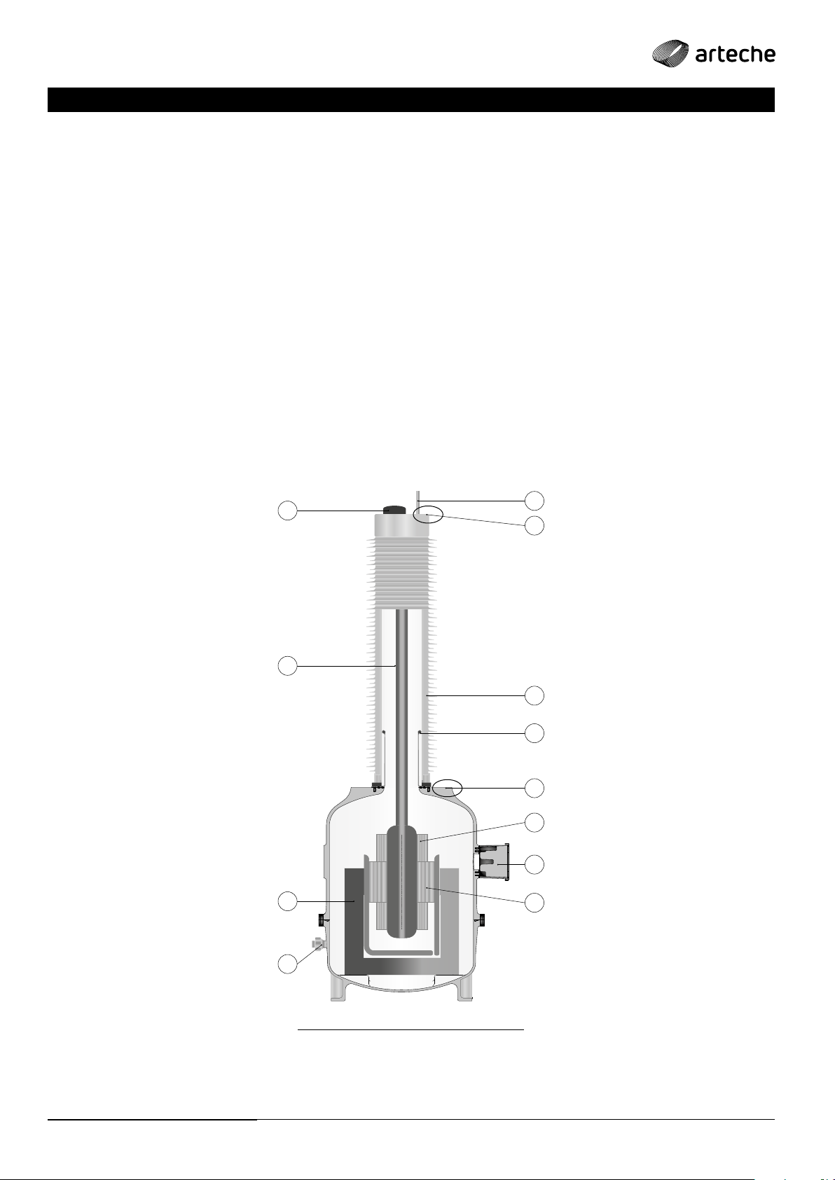
Annex I, contains the figures mentioned below.
If the transformer is in a horizontal position, to place it in a vertical
position, proceed as indicated in Fig. 1 and Fig. 2. During the lifting
process, the slings must always be kept in an upright position.
When the device is in a vertical position, movements can be
made:
› If the tank is not equipped with lifting eyes, as shown in Fig. 3.
› If the tank is equipped with lifting eyes, as shown in Fig. 4.
Once the equipment has been placed in an upright position, a
visual inspection is suggested so as to detect possible damage.
Precautions will be taken throughout the process to avoid
damaging the sheds of the synthetic insulator.
TRANSPORT/
ARTECHE’s packaging guarantees a correct transport to
destination.
These transformers can be transported both horizontally and
vertically. For transport, the transformer should be properly
attached to the packaging so as to avoid movement.
› Load and unload the transformer slowly and avoid sudden
movements.
› It must be secured to the truck to avoid movement.
› Keep truck acceleration under 5G, and the speed under:
• Unpaved road ___________ Max. 30 km/hour
• Secondary roads ___________ Max. 60 km/hour
• Highway (motorway) ___________ Max. 90 km/hour
DANGER
INJURIES from falls and tipping
› Do not place the equipment upside down or on its side
› Do not transport the equipment in conditions other than those mentioned
RECEIPT/
After receipt, check the packages for signs of shock, tampering,
etc. Any anomaly must be indicated on the transport
company’s receipt sheet and communicated to ARTECHE or
the equipment supplier.
Once the transformer has been unpacked, check that none of
the screws holding the insulator have become loose during
transport. If they have, tighten them according to the torque
indicated in Annex II. If any other type of anomaly appears,
inform ARTECHE or the supplier of the equipment.
Attach photos of the damaged transformers to the report.
› Possible damage to the packaging: Dents on the outside, open
packaging, etc.
› › Possible damage to equipment: Broken or defective insulator,
dented metal parts, damaged secondary terminal box, etc.
The packed units can be moved by forklift or with slings or
chains. Follow the safety markings on the packaging
DANGER INJURIES AND/OR FIRE
› Do not use damaged equipment
HANDLING/
DANGER
INJURIES from falls and tipping
› Do not place the equipment upside down or on its side
› Handle the transformer according to the instructions in this manual
› Never manipulate the transformer with internal pressure
› The slings used must be in good condition and suitable for handling the equipment
according to its weight, which is indicated on the nameplate
Under no circumstances should a transformer be manipulated by pulling on the primary terminals
This may cause damage to the equipment and void its warranty

4
High Voltage Instrument Transformers | UG
User Manual
INSTALLATION
MOUNTING ON THE STRUCTURE OR PLATFORM/
Check the information on the nameplate to verify that the
electrical characteristics match those of the system.
Carefully check to make sure that all four legs of the device sit
perfectly on the platform, before tightening the anchor screws.
If this is not the case, correct the defect, by wedging metal
plates or similar. Failure to do so may result in insulator breakage
or gas leakage.
PLACEMENT OF THE EQUIPOTENTIAL RING/
If the transformer requires an equipotential ring in order to be
mounted, it will be delivered disassembled.
The placement of the equipotential ring should be done with the
equipment in a vertical position and, if possible, already mounted
on the structure (without connections), to avoid damage during
handling.
The equipotential ring is screwed to the upper cover of the
device as shown in the Fig. 5 or Fig. 6. It is important to touch the
indicated screws only, otherwise the tightness of the equipment
could be lost.
Tightening must be carried out using a torque wrench, following
the indications in Annex II.
DANGER
INJURY AND/OR FIRE
› Do not install the equipment without following our specifications
› Use the transformers under proper service conditions and according to specifications
› Do not loosen any screws or fastening nuts, it can cause gas leaks. The pressure drop of SF6gas
can cause dielectric breakdown
CAUTION
ELECTRICAL DISCHARGE
› Do not wire or connect when the equipment is energized
› The ground terminal of the apparatus must be solidly earthed by means of a connection capable
of withstanding and conducting the line’s fault current to earth.
› Do not short-circuit the secondary circuit of the transformer
› Before energizing the equipment, check that the SF6has been filled to the nominal pressure
GAS FILLING/
The transformer will be delivered with a pressure of approx.
0.5kgf/cm2(0.05MPa relative) inside. Do not energize the
transformer until it has been filled with gas in accordance with
the pressure and composition values indicated on the nameplate.
If the internal pressure drops, it must be refilled with gas before
the minimum operating pressure indicated on the rating plate is
reached. The densimeter is equipped with two alarm contacts to
indicate the pressure drop and allow filling (Fig. 7).
Operation of the densimeter (Fig. 7):
› Green Zone: Normal operating zone.
› Amber Zone: Abnormal operating zone. The pressure is below
normal working pressure. The transformer maintains the
defined insulation level. Contact ARTECHE.
› Red Zone: Danger zone. Pressure drop below minimum level.
The transformer can still withstand the rated voltage with
the internal atmospheric pressure of the gas. Withdraw from
service and contact ARTECHE.
The densimeter is equipped with two alarms:
› The first alarm indicates the passage from the green to the
amber zone.
› The second alarm indicates the passage from the amber to the
red zone.
The handling of the gas, of the containers under pressure in which it is supplied and of the pressure
regulation instruments must be carried out by trained and certified personnel, and using appropriate
means, to reduce the risk of gas emission and possible damage due to the incorrect handling of
the containers. The emission of SF6to the atmosphere can constitute a punishable oense
SF6gas must comply with IEC 60376 or ASTM D2472.
The handling of the gas, of the containers under pressure in
which it is supplied and of the pressure regulation instruments
must be carried out by trained and certified personnel, and
using appropriate means, to reduce the risk of emission and of
possible damage due to incorrect handling of the containers.
The emission of SF6gas into the atmosphere may constitute a
punishable oense.
For more details, please refer to the ARTECHE gas filling manual.

5High Voltage Instrument Transformers | UG
User Manual
ELECTRICAL CONNECTIONS/
Primary connections
The primary terminal material is aluminum. They can have a tin
or silver coating with so as to prevent galvanic pair corrosion
and improve their contact.
Do not bring aluminum into contact with copper-based materials
unless special precautions are taken.
Material Finish Cleaning
Aluminum
Silver or tinned It is recommended to clean the contact surfaces
with a soft cloth (do not use a metal brush)
Unfinished
We recommended vigorously brushing the contact
surfaces with a soft metal brush (preferably
stainless steel) or sandpaper, until you see the
characteristic shine of the clean metal
Only impregnate the contact surfaces to be used with contact
grease, keeping the others clean. Remove excess grease to
avoid contamination.
Tightening must be carried out using a torque wrench, as shown on
the diagram plates and in Annex II.
Check the correct external wiring.
Secondary connections
The secondary winding(s) must be connected to earth through
one of its terminals, preferably in the secondary terminal box
itself.
In case of secondary with intermediate taps, the common
terminal must be grounded.
Check that the secondary connections are correctly tightened
and the contact surfaces are clean.
The screws of the lower cable gland cover, the block cover and
the terminals must be tightened to the torque specified Annex II.
In the terminal box there is a terminal block where the
secondary wires are connected. The disposition of the terminals
is indicated on the secondary marking plate on the inside of
the box cover.
A faulty contact or a bad connection can lead to rapid transformer deterioration
Avoid excessive torque, as the connector may suer damage such as cracks which may expand in the future and
cause it to break
An inadequate torque may cause improper contact and cause the terminals to heat up during operation
Any secondary one that is not loaded must be open and grounded at a single point
The current in a short-circuited secondary can reach dangerous values and can even destroy the device
CAUTION
Do not use the secondary terminal block as a step
To make or check the primary connections, a lifting platform or a ladder should be used,
maintaining the necessary safety conditions for work at height. In no case may the
terminal block be used as support

6
High Voltage Instrument Transformers | UG
User Manual
Grounding
The ground terminal of the transformer must be properly
connected to the ground network by a connection capable of
carrying the network’s fault current. Check that the connection
is tightened correctly and that the contact surfaces are clean.
The low voltage terminal of the primary voltage winding must
always be grounded when the transformer is in service. This
terminal is located inside the secondary terminal box (Fig. 8).
Always follow the Arteche Manual for instructions on transport,
storage, handling and installation.
ARTECHE instrument transformers do not require maintenance.
There are no moving parts and no components susceptible to
wear and tear, so no active maintenance is required.
However, some companies perform some monitoring operations
on instrument transformers as part of a general substation
maintenance program. These maintenance programs are not
intended to extend the life of the units, as the measures have no
impact on the state of the insulation or the performance of the
units. These programs serve to know the state of the isolation, so
that the user can make decisions based on the results obtained,
as well as detect situations that may be causing damage to the
unit.
We at Arteche, as manufacturers, do not establish any specific
measures, since the decision depends on:
› the resources available to each user,
› the location of the instrument transformer (can be a position
which is more or less critical),
› the environmental and electrical conditions that the unit must
withstand at each specific point,
› the history of the unit,
› the specific types or the problematic units,
› etc…
The following inspection points are only a suggestion in case
they are within the user’s maintenance policy.
1. Physical inspection:
a. Mechanical: Look for signs of impact, damage or loose
parts.
b. Electrical: Check the correct state of the electrical
connections.
c. Gas. Check the gas pressure as indicated on the
densimeter.
2. Dielectric tests:
d. Electrical tests to evaluate the insulation of the equipment.
For the test procedure, see Annex III.
3. Gas tests:
e. Tests performed on gas samples. The gas tests analyze
the state of the insulating liquid and show the properties
of the system in general.
4. Thermographic testing:
f. Use of thermographic cameras.
INSPECTION AND MONITORING
DANGER
ELECTRIC SHOCK AND/OR INJURY
› Everything should only be carried out by personnel who is qualified in the maintenance and verification
of the equipment
› Do not touch live parts
Densimeter alarm connections
Check that the alarm connections on the densimeter are
tightened correctly and that the contact surfaces are clean.
DANGER The transformer must be firmly grounded. A faulty or missing connection may cause damage or even
destroy the device

7High Voltage Instrument Transformers | UG
User Manual
Type Code Test Observations
Physical inspection
A1 Packaging Look for signs of rough handling.
A2 Insulator Check that is not damaged and is clean. Check that it is not loose, bent or broken.
A3 Primary
Terminals Check that they are not loose, bent or broken.
A4 Secondary
Terminal
Box
Check that it is not damaged and that it is securely fastened to the tank or transformer holder.
Check that no water enters the terminal box due to rain.
Check that the ventilation openings are not blocked.
A5
A6 Metal parts Check for dents, scratches or signs of corrosion.
A7 Unusual
behavior Check for unusual noises, vibrations or odors.
A8
Densimeter
and other
accessories
Check for damage.
B1 Primary
connections
Check that there is good contact, that there are no signs of corrosion and that all nuts and bolts are properly
tightened. The use of conductive grease is recommended to improve contact, such as Penetrox A13.
B3 Secondary
circuits
Check that all screws are properly tightened, and that there are no signs of corrosion. In the case of
secondary windings with intermediate taps, check that the connection matches the real transformer ratio.
Check that the unused secondary voltages are in open circuit.
B4 Grounding Check that the grounding terminal is correctly connected to the substation grounding network, that the
screws are correctly tightened and that there are no signs of corrosion.
B6
Voltage
transformer
neutral
connection
Check that the neutral terminal (N) of the primary winding is grounded.
Leaving it open when the transformer is energized will cause surges and damage to the
transformer.
B7 Readings Check that the reading values of the secondary match the values expected.
C1 Internal
pressure Check that the densimeter reading is in the green zone.
Dielectric tests
D2
Measurement
of the
Insulation
resistors
For field tests, the use of the megohmmeter (Megger) is very common, and the tests that are usually
done are:
› Among the secondaries
› Each secondary against ground
› N/P2 against secondary and Ground
In the case of new equipment, the value obtained does not provide any information, unless a short circuit
is detected. Generally, values above 100 MΩshould be expected. However, the comparison of long-term
values can help determine if a device is still in good working conditions.
Do not test at voltages above 3 kV AC or 1 kV DC.
Do not test for more than one minute. It is not recommended to repeat this test often as the
internal insulation could be damaged.
For details on the test procedure, follow Annex III
D3 Ratio test
The Portable Transformer Ratio Meter is commonly used to measure the ratio, excitation current and
polarity of windings. The values obtained are a reference that the transformer is in good condition and
can be energized.
They should not be compared with the results of factory tests carried out in the manufacturing plant
laboratory.
Due to the high precision required for this measurement, the actual uncertainty of the test must be taken
into account when testing on site.
For details on the test procedure, follow Annex III
Gas tests
E1 Dew point Checks for presence of moisture in the gas.
E2 Purity Checks the quality of the SF6.
E3 SO2The concentration of SO2is an indicator of the presence of decomposition products in SF6gas.
Thermograpic
tests
F1 Thermographic
analysis
Using thermographic cameras, hot spots can be detected during the operation of transformers. In most
cases, hot spots on instrument transformers occur at the primary terminals’ connection point to the line.
If present, check the integrity of the connectors, as well as their correct position and whether they are
correctly tightened.

8
High Voltage Instrument Transformers | UG
User Manual
TESTS PROGRAM/
When What
On arrival of the transformers at the warehouse or substation A1
After unpacking A2 - A3 - A4 - A6 - A8
During assembly A2 - A3 - A4 – A5 - A6 - A8 - B1 - B3 - B4 - B6 - C1 - D2 - D3
After energizing A7 - B7 - C1 - F1
Routine checks (weekly or monthly) A2 - A7 - B7 - C1
Annual checks A2 - A3 - A4 - A5 - A6 - A7 - A8 - B1 - B3 - B4 - B6 - B7 - C1 - F1
After re-connections, the load changes A7 - B1 - B3 - B4 - B6 - B7 - F1
After the fault conditions, the short circuits, etc. A3 - A7 - B1 - B3 - B4 - B6 - C1
See also “Careful check of the transformer” below.
After 1 year from start-up and after 5 years from start-up, if the
values are normal and there is no considerable increase, perform
an analysis after 15 years from start-up, and then every 5 years
E1 - E2 - E3
CAREFUL CHECK OF THE TRANSFORMER/
It is recommended that all regular tests be repeated after
a long period of operation (about 20 years), or if a major
network disturbance has occurred that could damage the
transformer (e.g. a short circuit with current or duration values
higher than the nominal ones, or over-voltages caused by the
malfunctioning of the switches).
QUICK TROUBLESHOOTING GUIDE
Phenomenon Control item Cause Countermeasure
Abnormal
voltage
indication
› Visual control
› Load control
› Measuring insulation
resistance
› Analyzing gas
Internal issue
Contact ARTECHE
Partial discharges
Short circuit
alarm in the
secondary
Ferro-resonance
Loss of contacts Repairing the issue
Contact ARTECHE
1. Equipment name
2. Serial number
3. Type
4. Manufacture date
5. Description of the issue
6. Results of the controls
Strange
noises,
smells and
vibrations
Winding short-circuit
Contact ARTECHE
Winding error
Relay trip
and non-trip Overload Correct loading
Gas pressure
drop
› Locate gas leaks
› Determine pressure losses
Deteriorated sealing
Contact ARTECHE
Surface corroded
by the
sealing parts
Oxidation
and
corrosion
› Visual check
› Examine environment
Peeled-o coating
Repainting
Corrosive atmosphere
Insulation
loss Wet or contaminated
Clean and dry o.
If the resistance
is not restored in
spite of your eorts,
contact ARTECHE

User Manual - Annex I High Voltage Instrument Transformers | UG
ANNEX I
› UG-72..525
HANDLING AND CONNECTION

1
User Manual - Annex I
High Voltage Instrument Transformers | UG
›Fig. 1: Lifting
C
›Fig. 2: Lifting
›Fig. 3: Movement ›Fig. 4: Movement

2
User Manual - Annex I
High Voltage Instrument Transformers | UG
›Fig. 5: Placement of the equipotential ring
›Fig. 6: Placement of the equipotential ring
›Fig. 7: Densimeter ›Fig. 8: Neutral grounding

User Manual - Annex II High Voltage Instrument Transformers | UG
ANNEX II
METRICS
HIGH VOLTAGE STEEL 8.8 (ZN-0) STAINLESS STEEL A2-70
GENERAL
Metal-Metal
Insulator
Bushing
Valves
Rupture Disc
GENERAL
Metal-Metal
(except threads
on copper)
Insulator
Blushing
Vales
Rupture Disc
M3 - - 0.6 -
M4 - - 2 -
M5 - - 4 -
M6 4.41 4.41 6 4.4
M8 10.8 10.8 15 10.8
M10 21.1 21.1 30 21.1
M12 36.3 24.5 48 24.5
M14 - - 60 30
M16 91.2 78.4 120 78.4
M20 177 90 230 90
M24 304 - 380 -
M30 608 - - -
TIGHTENING TORQUES
NOTE: If a torque dierent from that indicated in this table is indicated on the drawing or plates of the equipment, the torque indicated on the drawing
or plate must be applied.
Tightening torque (N-m) with -5%,+0% tolerance.

User Manual - Annex III High Voltage Instrument Transformers | UG
ANNEX III
ELECTRICAL FIELD TESTING
All ARTECHE transformers are tested at our High Voltage laboratories, under the strictest criteria of international standards and/or
under specific client standards/specifications when so requested. All of it under a thorough quality system, certified under ISO 9001.
However, it is normal for pre-operative tests to be performed in order to confirm certain important equipment values. The following
is a guide to the most common on-site tests and the proper way to perform them on ARTECHE brand transformers.
This annex applies to the following equipment:
› Gas Insulated Voltage Transformers, UG Series, Models UG-72..550.

5
User Manual - Annex III
High Voltage Instrument Transformers | UG
The measurement of the insulation resistance is done to check
the integrity of the transformer insulation and to ensure that it
has not been internally damaged during transportation. This test
depends largely on the design of the transformer, the general
configuration of the test, the instruments used, etc. The values
obtained may not be representative of the actual state of the
insulation. If this test is performed, it is recommended to contact
the manufacturer.
For field tests, the use of the megohmmeter (Megger) is very
common, and the tests that are usually done are:
› N/P2 against secondary and Ground.
› Each secondary against ground.
› Among the secondaries.
In the case of new equipment, the value obtained does not
provide any information, unless a short circuit is detected.
Generally, values above 100 MΩshould be expected. However,
the comparison of long-term values can help determine if a
device is still in good working conditions.
Do not test at voltages above 3 kV AC or 1 kV DC.
Do not test for more than one minute. It is not recommended
to repeat this test often as the internal insulation could be
damaged.
INSULATION RESISTANCE MEASUREMENT
Primaries vs. Secondaries+ Ground N/S+G (Fig. 1)
› The line cable of the measuring equipment must be connected
to the terminals of the primary winding (A-N) that are short-
circuited with each other, and the grounding plate (N) must be
disconnected from the primary winding.
› The ground cable of the measuring instrument must be
connected to the short-circuited secondary terminals together
with the ground terminals on the secondary terminal block as
well as the tank.
Secondaries vs Ground S/G (Fig. 2)
› Primary terminal A must be disconnected and the neutral
connection of the (N) primary winding must be grounded.
› The line cable of the measuring equipment must be connected
to the short-circuited secondary terminals.
› The grounding cable of the measuring equipment must be
connected to the tank.
Between secondaries S/S
› This test is only applicable to transformers having more than
1 secondary.
› Primary terminal A must be disconnected and the neutral
connection of the (N) primary winding must be grounded.
› The secondaries to be assessed will be connected; one to
the line cable and the other(s) to the ground cable of the
measuring equipment.
› The test is repeated with each secondary.
INDUCTIVE VOLTAGE TRANSFORMERS/
›Fig. 1 ›Fig. 2
A
NG
+ -
A
N
G
+ -

6
User Manual - Annex III
High Voltage Instrument Transformers | UG
The Portable Transformer Ratio Meter (TTR) is commonly used
to measure the ratio, excitation current and polarity of windings.
The values obtained are a reference that the transformer is
in good condition and can be energized. They should not be
compared with the results of factory tests carried out in the
manufacturing plant laboratory.
Due to the high precision required for this measurement, the
actual uncertainty of the test must be taken into account when
testing on site.
The TTR contains 4 terminals (this configuration may vary
depending on the manufacturer):
› H1: Black excitation terminal.
› H2: Red excitation terminal.
› X1: Black secondary terminal.
› X2: Secondary red terminal.
TRANSFORMER RATIO TEST
This test verifies the transformer ratio and polarity, and displays
a “+” signal if correct, and a “-” signal if inverted. To carry out the
test, proceed as follows (Fig. 3).
› The excitation terminals (clamps marked “H”) will be
connected to the transformer’s primary terminal:
• H1 will be connected to the primary terminal of equipment A.
• H2 will be connected to the ground terminal.
› The clamps marked “X” will be connected to the transformer’s
secondary terminals:
• X1 will be connected to 1S1. When the secondary has sockets,
you must connect X1 to the socket of the secondary terminal
which is to be tested.
• X2 will be connected at the end of the secondary terminal.
• This test must be applied to each secondary separately;
in case the transformer has more than 1 secondary, the
secondary(s) which are not to be tested must be left open.
INDUCTIVE VOLTAGE TRANSFORMERS/
›Fig. 3
A
N
T.T.R.
H1
IS1
H2
X2
X1
IS2 IS3 IS4

©ARTECHE
User Manual
For more detailed information, please visit us at arteche.com
Subject to change without notice
MU_HV_UG_EN
V: A0 12/01/2021
This manual suits for next models
1
Table of contents
Other Arteche Transformer manuals
Popular Transformer manuals by other brands

Torus Power
Torus Power WM AVR-2 ELITE Series owner's manual

Tripp Lite
Tripp Lite Full Isolation UPS Systems none Important safety instructions

ELEQ
ELEQ RM17 installation guide

Audioplex
Audioplex THE BEAST installation manual

Ormazabal
Ormazabal velatia transforma.dis General instructions

Mackie
Mackie PATX60 quick start guide