Artila Matrix-310 Installation instructions

Copyright © Artila Electronics Co., Ltd. All Rights Reserved.
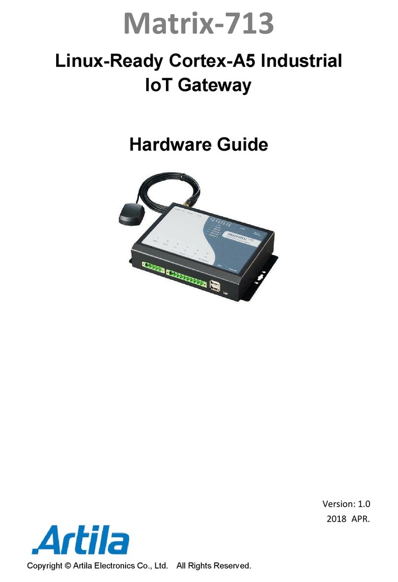
Matrix-310
Programmable Industrial IoT Gateway
Hardware Guide
Version: 1.0
2023 January

Matrix-310 ardware Guide
ARTILA
2
Trademarks
The Artila logo is a registered trademark of Artila Inc. All other trademarks or
registered marks in this manual belong to their respective manufacturers.
Disclaimer
Information in this document is subject to change without notice and does not
represent a commitment on the part of Artila.
Artila provides this document as is, without warranty of any kind, either expressed
or implied, including, but not limited to its particular purpose. Artila reserves the
right to make improvements and/or changes to this manual, or to the products
and/or the programs described in this manual, at any time.
Information provided in this manual is intended to be accurate and reliable.
owever, Artila assumes no responsibility for its use, or for any infringements on
the rights of third parties that may result from its use.
This product might include unintentional technical or typographical errors.
Changes are periodically made to the information herein to correct such errors,
and these changes are incorporated into new editions of the publication.
FCC AND IC INFOR ATION:
This Class A digital apparatus complies with Part 15 of the FCC rules and with
Canadian ICES-003
Operation is subject to the following two conditions:
1. This device may not cause interference and
2. This device must accept any interference. Including interference that may
cause undesired operation of the device.

Matrix-310 ardware Guide
ARTILA
3
Document Amendment History
Revision
Date Remark
V 1.0 2023 Jan. Initial

Matrix-310 ardware Guide
ARTILA
4
Table of Contents
1. Introduction .................................................................................................... 5
1.1 Features .................................................................................................. 5
1.2 Specifications ( ardware)........................................................................ 6
1.3 Specifications (Software) ......................................................................... 8
1.4 Packing List ............................................................................................. 8
1.5 Optional Accessory.................................................................................. 8
2. Layout ............................................................................................................. 9
2.1 Connector & LED Indicator ...................................................................... 9
2.2 Mounting ................................................................................................. 9
2.3 Dimension ............................................................................................... 10
3. Pin Assignment and Definitions .................................................................... 11
3.1 Power Connector ..................................................................................... 11
3.2 LED Indicators ......................................................................................... 11
3.3 Ethernet LAN Port ................................................................................... 12
3.4 Console Port............................................................................................ 12
3.5 Serial Port ............................................................................................... 13
3.6 Relay Out ................................................................................................ 14
3.7 Digital Input ............................................................................................. 15
3.8 ID Setting ................................................................................................ 16
3.9 Reset Button............................................................................................ 17
3.10 SD card Socket ....................................................................................... 17

Matrix-310 ardware Guide
ARTILA
5
1. Introduction
Matrix-310 from Artila provides multi-communication via an Arduino-based, C/C++
programmable industrial IoT gateway. With the integrated ESP32 Xtensa Dual-Core
32-bit LX6 Microprocessor, Artila’s IoT gateway provides up to 240 M z of
frequency, as well as Wi-Fi (802.11b/g/n, 2.4G z single band) and dual-mode
Bluetooth.
It features dual available / reliable networks, dual Serial ports and digital In/Out
connectivity for transmission of acquired data to the cloud makes it ideal for real-time
monitoring and predictive maintenance also optimization and deployment of factory
applications, such as industrial automation, environment monitoring and smart city
infrastructure.
The gateway provides software via an Arduino IDE. Ideal for real-time monitoring and
predictive maintenance functions, which are commonly performed in Industrial IoT
environments, the Matrix-310 provides Dual Serial ports and digital In/Out
connectivity for data transmission to the cloud. Users can install the ESP32 Arduino
core through board manager of the Arduino IDE.
1.1 Features
Rugged Design for arsh Industrial Environment
Arduino-Based Programmable Industrial IoT Gateway
Espressif ESP32 Xtensa® Dual-Core 32-bit LX6 Microprocessor, 240 M z
Onboard 520KB SRAM, 4MB Flash
Suitable for Accessing Modbus Device
Easy Software Development (IDE/C-language/Arduino/Micro Python)
One LAN Port, 10/100Mbps Ethernet
Two Serial Ports: 1xRS-485 & 1xRS-232
Wireless: IEEE 802.11b/g/n, 2.4G z Single
2x Digital Inputs and 1xRelay out
ID Setting by Rotary Switch
One Micro-SD Socket Internally
Wide-Range Temperature Operating
DIN-Rail Mounting, Optional Wall-Mounting
Protective Earthing Design with Chassis Ground Screw

Matrix-310 ardware Guide
ARTILA
6
1.2 Specifications (Hardware)
SOC (ESP32-WROO -32U)
• MCU: ESP32-D0WD-V3, Xtensa® dual-core 32-bit LX6 microprocessor
• Frequency: Up to 240M z
• SDRAM: 520KB for data and instructions
• Flash: 448KB for booting and core functions
• Wi-Fi (ESP32): IEEE 802.11b/g/n, 2.4G z single band
FCC ID: 2AC7Z-ESP32WROOM32U
Network Interface
• Type: 1 x 10/100Mbps Ethernet (SPI interface)
• Connector Type: RJ45
TTY (Serial) Ports
• COM1: Isolated RS-485 (1500Vrms isolation)
• COM2: RS-232
• Direction Control (RS-485): Auto, by software
• RS-485 Signal: Data+, Data-
• RS-232 Signal: TX, RX
• Connector: Terminal block
• LED Indicator: YES
TTY (Serial) Port Parameters
• Baud Rate: Up to 921.6Kbps
• Parity: None, Even, Odd, Mark, Space
• Data Bits: 5, 6, 7, 8
• Stop Bits: 1, 1.5, 2
Relay Output
• 1 x Digital Output Channels (Signal Relay)
• Contact Rating: 12[email protected] / 3[email protected]
• Max. switching Voltage: 125VAC/60VDC
• Max. switching Current: 2A
• Signals: NC, NO, COM

Matrix-310 ardware Guide
ARTILA
7
Digital Input
• 2 x Digital Input Channels
• Isolation Protection: 5000Vrms (Photo Coupler)
• Logical igh: 5~24VDC
• Logical Low: 0~1.5VDC
Power Requirement
• Input Voltage: +9~+40VDC
• Connector: Terminal block
• Typical Power Consumption: 12VDC@150mA
Console
• 1 x Micro-USB console port
• Flashing applications to the chip & Debug
SD Slot
• 1 x microSD socket inside (SPI Interface)
• SD 2.0 compliant, supports SD C
ID Setting
• 1 x 8-position rotary switch
• Device ID setting or Application mode selection
General
• Watchdog (WDT): Yes (ESP32)
• Real-time Clock (RTC): Yes (ESP32)
• Dimensions (W x x D): 30 x 140 x 95mm (1.18 x 5.51 x 3.74in)
• Net Weight: 424.5g (0.93lb)
• Operating Temperature: 0~70°C (32~158°F)
• Regulation: CE Class A, FCC Class A
• Installation: DIN-Rail mounting or Wall mounting

Matrix-310 ardware Guide
ARTILA
8
1.3 Specifications (Software)
Easy to Use C/C++ Platform (Arduino ESP32)
• Matrix-310 is C/C++ programmable, Arduino (ESP32) compatible industrial IoT
platform
• Installed Arduino core (ESP32) through board manager of Arduino IDE
Free Application Development Tools
• Free Xtensa® C/C++ toolchain
• Free Arduino official IDE
• Free Microsoft Arduino plugin for VS code
1.4 Packing List
atrix-310: Programmable Industrial IoT Gateway
1.5 Optional Accessory
PWR-12V-1A: 100~240VAC to 12VDC@1A Power Adaptor

Matrix-310 ardware Guide
ARTILA
9
2. Layout
2.1 Connector & LED Indicator
2.2 ounting

Matrix-310 ardware Guide
ARTILA
10
2.3 Dimension
Dimensions (W x x D): 30 x 140 x 95mm (1.18 x 5.51 x 3.74in)
Unit: mm

Matrix-310 ardware Guide
ARTILA
11
3. Pin Assignment and Definitions
3.1 Power Connector
Connecting +9 ~ +40VDC power line to the Power in terminal block.
3.2 LED Indicators
The LED provides the Matrix-310 operation information. The LED status is described
as follow:
“PWR” (Power LED indicator): PWR LED turns on (green color) after 3.3Vdc
power activity
“RDY” (Ready LED indicator): RDY LED turns ON (green color) when ESP32 is
ready for operating.
“CO 1” & “CO 2” (Serial Port LED indicator): Bi-color LEDs indicate the data
traffic at the serial ports: COM1(RS485) and COM2(RS232).
When D+/RX line is high: Yellow light is ON
When D-/TX line is high: Green light is ON
“LAN” (Network LED indicator): Link and Activity LED will turn ON when the
Ethernet cable is connected. When there is network data traffic, this Bi-color LED
will light up.
“WIFI” (WIFI LED indicator): This Bi-color LED activity is defined by user after
enable “WIFI” function.

Matrix-310 ardware Guide
ARTILA
12
3.3 Ethernet LAN Port
There is a 10/100Mbps Ethernet by RJ45 connectors.
It is designed via SPI interface (Mode 0 & mode 3) connected to MCU (ESP32)
The Ethernet Port use RJ45 connector. Pin-Assignment as below:
PIN Signal
1 ETx +
2 ETx -
3 ERx +
6 ERx -
3.4 Console Port
There is one Console port by micro-USB connector.
A Micro-USB port is used for power supply (+5VDC) to the board (only basic
operation and flashing) and for flashing applications to the MCU (ESP32) as well as
the communication with the chip via the on-board USB-to-UART bridge.

Matrix-310 ardware Guide
ARTILA
13
3.5 Serial Port
The Matrix-310 has two serial ports:
One RS-485 port (COM1: D+/D-)
One RS-232 port (COM2: RX/TX)
RS-485 is designed without isolation that automatically direction controlled via
software
The pin assignment is shown as following table:
Port No. Pin1 Pin2 Pin3 Pin4 Pin5
COM1 RS-485 D+ D- -- -- GND
COM2 RS-232 -- -- RX TX GND
Enable/Disable Termination resistor for RS-485 (JP3)
The Matrix-310 provides on-board 120Ohm termination resistor for each RS-485
port. To enable the termination resistor, please remove the upper cover of the
Matrix-310, and the adjust the associated jumper to short as below:
Termination Resistor Disabled (default)
Termination Resistor Enabled
1 2 3
1 2 3
JP3

Matrix-310 ardware Guide
ARTILA
14
3.6 Relay Out
There is one Digital Output Channels (Signal Relay).
• Contact Rating: 125VAC@0.5A / 30VDC@1.0A
• Max. switching Voltage: 125VAC/60VDC
• Max. switching Current: 2A
• Signals: NC, NO, COM
• 1 Form C configuration
COM: Common ground

Matrix-310 ardware Guide
ARTILA
15
3.7 Digital Input
There are two Digital Input channels
The specification of the isolated input channels is:
Logical igh: 5~24Vdc
Logical Low: 0~1.5Vdc
Isolation resistance: 10
11
Ohms@500VDC
Response time: 20µs (Max.)
Isolation: 5000Vrms (Photo Coupler)
DIx: Isolated digital input channels.
COM: Common ground
DI 1~2
COM

Matrix-310 ardware Guide
ARTILA
16
3.8 ID Setting
Matrix-310 equips an 8-position rotary switch for Device ID setting or Application
mode selection.
To program/define 8-positions by following the table listed below:
( : igh, L: Low)
8 positions (0~7)
ESP32 0 1 2 3 4 5 6 7
Pin06 (GPI34) L L L L
Pin11 (GPIO26) L L L L
Pin07 (GPI35) L L L L
For example,
Set ID at “Position 0” response to MCU is “111” (1= igh / )

Matrix-310 ardware Guide
ARTILA
17
3.9 Reset Button
Press this Reset Button (inside the cabinet) to restart the system.
3.10 SD card Socket
There is a micro-SD card socket inside as data storage.
After removed top cover, it can access the SD card.
Micro-SD card socket
Reset Button
Table of contents
Other Artila Gateway manuals

Artila
Artila Matrix-702 Installation instructions

Artila
Artila Aport-212 User manual

Artila
Artila Matrix-713 Installation instructions

Artila
Artila Aport-211S User manual

Artila
Artila Matrix-750 Installation instructions

Artila
Artila Matrix-710 Installation instructions

Artila
Artila Matrix-752 Installation instructions

Artila
Artila Aport-213 User manual
Popular Gateway manuals by other brands

Shaw
Shaw Gateway HDPVR SELF-INSTALLATION INSTRUCTIONS

Arris
Arris Buckeye user guide

Patton electronics
Patton electronics SmartNode 4940 Series quick start guide

Pyramid Solutions
Pyramid Solutions BridgeWay J1939 Quick Start Configurations

NetComm
NetComm NF18ACV quick start guide

ZyXEL Communications
ZyXEL Communications Prestige P-662HW-61 user guide