artisan 2618-1B Instruction Manual

2618.2-1B
Cylinder Bed Compound Needle Feed
Lockstitch Sewing Machine
Instruction Manual
and Parts Catalog
Artisan Sewing Supplies, LLC, San Francisco, California
artisan

CONTENTS
INSTRUCTION MANUAL
Ⅰ.PRECAUTIONS BEFORE STARTING OPERATION................................................ 1
Ⅱ.SPECIFICATIONS....................................................................... 1
Ⅲ.CAUTIONS ON USE ..................................................................... 2
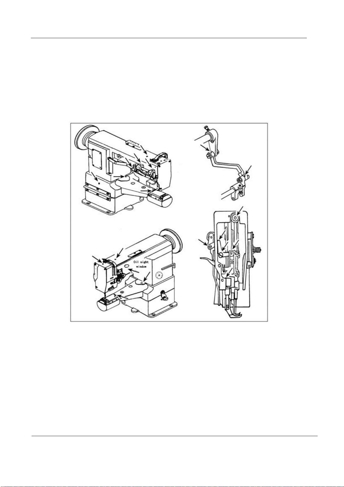
1. Lubrication ......................................................................... 2
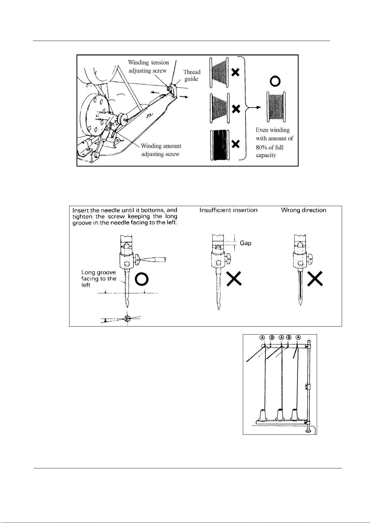
2. Winding of bobbin thread ............................................................ 2
3. Attaching the needle ................................................................ 3
4. Threading of needle threads ......................................................... 3
5. Setting of bobbin ................................................................... 4
6. Threading of bobbin threads......................................................... 4
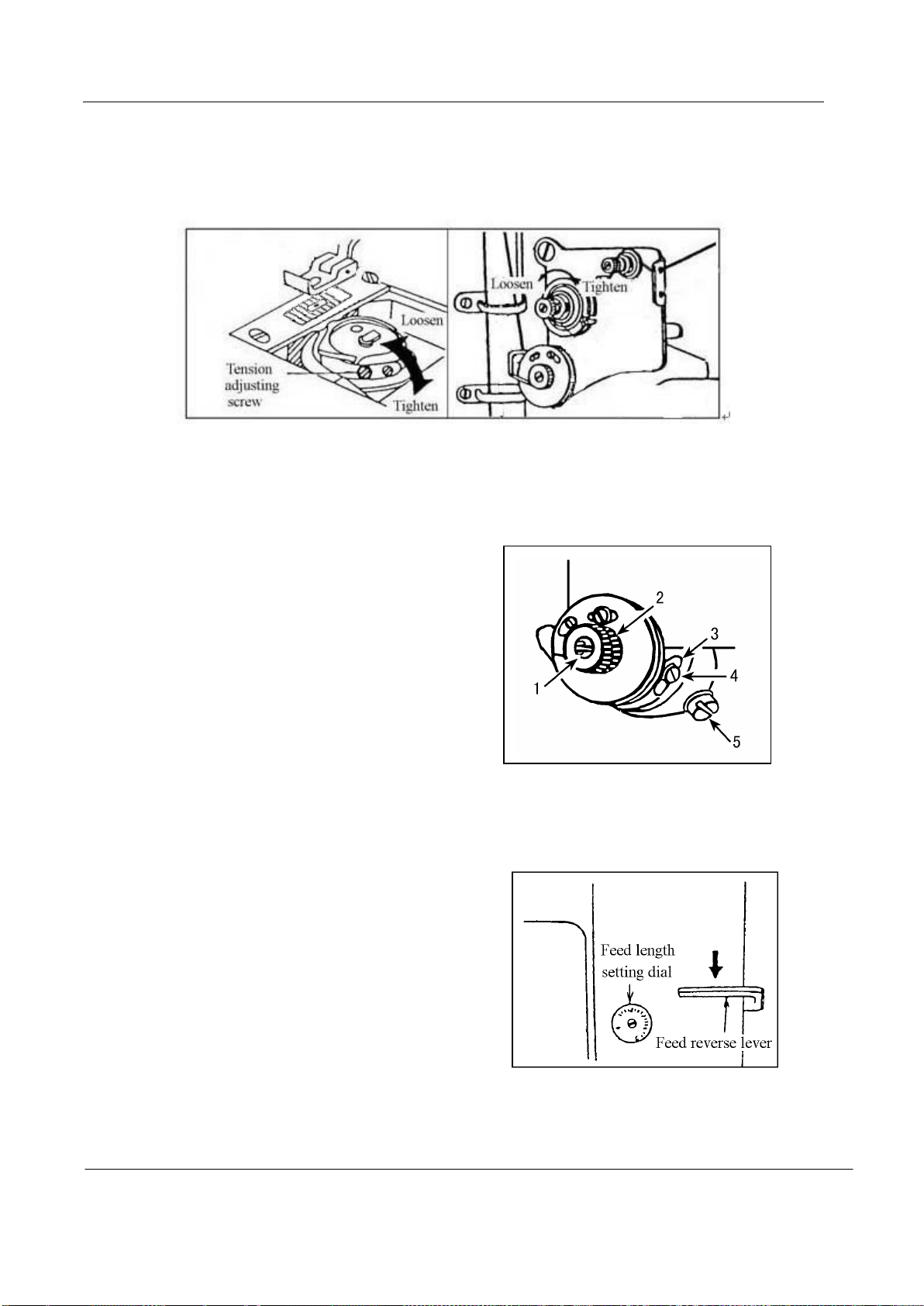
7. Thread tension ...................................................................... 4
8. Thread take-upspring ................................................................ 5
9. Adjusting the stitch length ........................................................ 5
10. Adjusting the pressure of the presser foot ......................................... 6
11. Adjusting the presser foot and the walking foot .................................... 6
12. Timing between rotating hook motion and needle motion .............................. 6
13. Relationship between hook motion and opener motion ................................. 7
14. Relationship between needle motion and feed dog motion ............................. 7
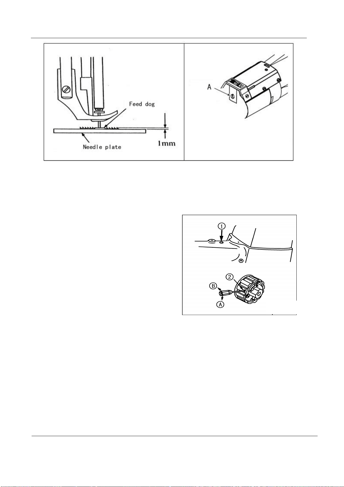
15. Adjusting the height of the feed dog ............................................... 7
16. Safety mechanism ................................................................... 8
CATALOG
A. ARM BED AND ITS ACCESSORIES.......................................................... 9
B. THREAD TENSION REGULATOR MECHINISM.................................................. 12
C. ARM SHAFT MECHANISM................................................................. 15
D. NEEDLE BAR &THREAD TAKE-UP LEVER MECHANISM........................................ 17
E. PREAAER FOOT MECHANISM ............................................................ 19
F. STITCH REGULATOR MECHANISM.......................................................... 22
G. FEEDING AND FEED LIFTING &ROTATING HOOK SHAFT MECHANISM........................... 25
H. HOOK SADDLE MECHANISM............................................................... 27
I. ACCESSORIES ....................................................................... 29

—1 —
Ⅰ、PRECAUTIONS BEFORE STARTING OPERATION
1. Safety precautions
1)When turning the power on, keep your hands and fingers away from the area around/under the needle
and the area around the pulley.
2)Power must be turned off when the machine is not in use, or when the operator leaves the seat.
3)Power must be turned off when tilting the machine head, installing or removing the “V” belt,
adjusting the machine, or when replacing.
4)Avoid placing fingers, hairs, bars etc., near the pulley, “V” belt, bobbin winder pulley, or motor when
the machine is in operation.
5)Do not insert fingers into the thread take-up cover, under/around the needle, or pulley when the
machine is in operation.
2. Precautions before starting operation
1)Do not operate the machine before lubricating it.
2)When a new sewing machine is first turned on, verify the rotational direction of the pulley with the
power on(the pulley should rotate counterclockwise when viewed from pulley).
3)Verify the voltage and (single or three) phase with those given on the machine nameplate.
3. Precautions for operating conditions
1)Avoid using the machine at abnormally high temperatures(35℃or higher)or low temperatures(5℃
or lower).
2)Avoid using the machine in dusty conditions.
Ⅱ、SPECIFICATIONS
GC2268-1B
Max. sewing speed 2200 rpm
Needle DP×17 18-23#
Needle bar stroke 36 mm
Thread take-up lever stroke 74.5 mm
Stitch length 9 mm
Presser foot stroke By Hand 8 mm / By Knee 14 mm
Alternating movement 2-5 mm
Bed size In dia / Length 71 mm / 222 mm
Lubrication Manual

—2 —
Ⅲ、CAUTIONS ON USE
1. Lubrication
·When a new sewing machine is first operated, or when a sewing machine is operated which is out of
use for long period of time, it will be necessary to oil through the oil holes after removing the
rubber plugs shown below.
·See dripping of oil through the oil sight hole to check oiling condition during operation.
For oil, Use white spindle oil
2. Winding of bobbin thread
Note: When bobbin thread is wound, keep the presser foot lifted.
Adjustment:
·Tension of wound thread
Slack winding is recommended for polyester thread and nylon thread.
·Conically wound thread
Move the thread guide toward smaller diameter of wound thread layer.
·Length of wound thread
Loosen the thread length adjusting screw to increase length of thread and tighten the screw to
decrease length of thread.

—3 —
3.Attaching the needle
Note: Before installing the needles, be sure to turn off the power.
4.Threading of needle threads
1)Pass each needle thread through thread guide“A”.
Note: When thin slippery thread (polyester
thread or filament thread, for example)
is used pass the thread through thread
guides“B” as wall.
2)With the take-up lever located at the upper
most position, pass each needle thread in
the order shown in the following figure.
Note: Pressing the upper thread loosening button shown in the figure below opens the saucer of
the upper thread tension adjuster, and the upper thread can easily pulled out

—4 —
5.Setting of bobbin
1)Pulling out 5cm thread tail from the bobbin.
2)Hold the bobbin so that the bobbin thread is would in
right direction and put it into the hook.
6.Threading of bobbin threads
1)Put the hook into the bobbin case and press
down the latch ①.
2)While holding the needle threads by left hand, rotate the
hand-wheel one turn by right hand.
By pulling up the needle threads, as shown in the figure, the bobbin threads will be lifted.
Each combination of bobbin thread and needle thread should be aligned and led backward.

—5 —
7.Thread tension
1)Adjusting the bobbin thread tension
Turn tension screw, clockwise to increase the bobbin thread tension, or counter clockwise to
decrease it.
2)Adjusting the needle thread tension
·Needle thread tension should be adjusted in reference to bobbin thread tension.
·Turn tension nut clockwise to increase the needle thread tension, or counter clocking to decrease it.
·Needle thread tension can be also adjusted for special fabric and thread by changing intensity and
movable range of slack thread adjusting spring.
8.Thread take-upspring
1)To change the stroke of thread take-up spring
·Loosen screw“4”in the stopper, and
move stopper“3”to the right or left.
·Move the stopper to the right to
increase the stroke of the thread
take-up spring, or to the left to
decrease it.
2)To change the tension of the thread take-up spring
Loosen nut“2”and screw“5”.Turn spring shaft“1”counter clockwise to increase the tension
of the spring, or clockwise to decrease it. Fit a screwdriver in the spring shaft and turn it until the
desired tension is provided.
9.Adjusting the stitch length
Turn stitch length dial counter-clockwise
to bring the desired value to the top of the dial so
that the value is aligned with the pin.
Reverse feed stitching
1)The machine performs reverse feed stitching as
long as the lever is held depressed.
2)The moment you release the lever, the machine
resumed the normal stitching mode.

—6 —
10.Adjusting the pressure of the presser foot
Pressure to fabric can be adjusted by turning the pressure
adjusting screw.
11.Adjusting the presser foot and the walking foot
1)Loosen not 1, and change the position of the cam rod
boss accordingly.
Highest position---The stroke is maximized. “A”
Lowest position--- The stroke is minimized. “B”。
2)Alternate vertical motions of the walking foot and presser foot
The alternate vertical strokes of the walking foot and presser foot
·Loosen screw ②of the top feed crank.
·Bring the thread take-up lever to its highest position, and lower the presser bar lifting lever. Move
top feed crank ③to left“A”to increase the stroke of the presser foot, or to the right“B”to
increase it.
12.Timing between rotating hook motion and needle motion
1)Set feed length (stitch length) to “6” on the
feed setting dial.
2)When needle is lifted 2.4mm from the lower
dead point, as shown in Figure, the
following positional relationship should
be maintained.
·The upper edge of needle eye should be
2.3 mm below the hook point.
·The hook point should be located at the
center of needle axis.
·Gap between the hook point and the side
face of needle should be 0.05mm.

—7 —
13.Relationship between hook motion and opener
motion
1)Turn the balance wheel by hand and stop when the
opener holder is located most remotely from the
throat plate.
2)Make sure gap between the bobbin case holder A
and the opener is approximately 0.2 mm.
3)If the gap is too large or small , loosen the opener
holder set screw B and adjust position of the opener.
14.Relationship between needle motion and
feed dog motion
1)Set feed length to “0” on the feed setting dial
2)Set the needle at the lowest position.
3)Lean the machine head backward, remove the back cover, loosen screw B and C.
4)Adjust the distance between presser rod and vibration prevention rod to 9 mm.
5)After the completion of adjustment, fully tighten the screws B and C.
Note:
At this time make
certain that needle can
enter the feed dog needle
hole at the center of the
hole.
15.Adjusting the height of the feed dog
The max. Height of the feed dog from the surface to the needle plate is normally 1mm.
To adjust this height:
1)Set the stitch length at minimum.
2)Turn the pulley so as to raise the feed dog to it highest position.
3)Loosen the screw“A”, adjust the height of the feed dog .
4)Tighten the screw“A”after adjustment.

—8 —
16.Safety mechanism
If the thread is caught in the hook while the sewing machine is in operation, the safety
mechanism actuates to idle the lower sprocket only if the thread is caught in the hook while the
sewing machine is in operation, the safety mechanism actuates to idle the lower sprocket only.
1)How to reset
·Remove the thread caught6 in the hook
·Pressing push button ①, strongly turn the
pulley in the direction opposite to its
normal rotational direction.
2)Safety load
Turn adjustment screw ② in direction“A”
(clockwise) to increase the safety load, or in
direction “B”(counter-clockwise) to decrease it.

-9-
A. ARM BED AND ITS ACCESSORIES

-10-
Pig.
No. Part No. Description
GC2268-1B
Remarks
A01 HA300B2170 Face plate screw 9SM11/64(40)×9
A02 H4730B8001 Guide mounting plate 1
A03 H4727B8001 Face plate 1
A04 HA300C2030 Screw 1SM11/64(40)×8
A05 H4731J8001 Holder 1
A06 H4711J7101 Oil pipe 1
A07 HH61B17101 Oil pipe 1
A08 H411040160 Screw 2
A09 HA100E2150 Screw 2SM11/64(40)×10
A10 H4722E8001 Washer 2
A11 H4721E8001 Guide for slide block 1
A12 H4716B8001 Oil guard plate 1
A13 H4718B8001 Arm side cover 1
A14 HA300B2170 Face plate screw 4SM11/64(40)×9
A15 H4719B8001 Arm side cover 1
A16 H4717B8001 Thread take-up guard 1
A17 HA300C2030 Screw 2SM11/64(40)×8
A18 H32175B304 Felt 1
A19 H4715B8001 Oil cup 1φ13
A20 H4735B8001 Oil cup 1φ22
A21 HA700B2060 Screw 2SM11/64(40)×8
A22 H2400B2100 Thread guide 1
A23 HA300B2090 Oil cup 2φ8.8
A24 H2400B2060 Oil guard plate block 1
A25 H3200B2060 Oil guard 1
A26 H2400B2070 Thread guide 1
A27 H2400B2080 Screw 2SM3/16(28)×13
A28 H4726B8001 Thread guide 1
A29 H3000D2160 Screw 1SM9/64(40)×6.5
A30 H3212B0066 Thread guide 1
A31 H3200B2100 Screw 1SM9/64(40)×6.5
A32 H4769E8001 Tension releasing pin 1
A33 H4736B8001 Oil cup 1φ15
A34 HA307B0673 Oil cup 1φ19
A35 HH60B68001 Arm 1
A36 HH60B78001 Arm bed 1
A37 HH60B98001 Felt 1
A38 HH60B88001 Oil reservior 1
A39 H4107B0672 Supporter 1
A. ARM BED AND ITS ACCESSORIES

-11-
Pig.
No. Part No. Description
GC2268-1B
Remarks
A40 HE107I8001 Screw 1M6
A41 H4100B2090 Washer 1
A42 H4100B2070 Screw 1SM1/4(24)×9.8
A43 H4100B2060 Link plate 1
A44 H4100B2100 Hinge 1
A45 H4100B2110 Hinge screw 6SM1/4(24)×9.8
A. ARM BED AND ITS ACCESSORIES

-12-
B. THREAD TENSION REGULATOR MECHINISM

-13-
Pig.
No. Part No. Description
2618-1B
Remarks
B01 H3221B3142 Tension releasing plate 1
B02 H3221B6811 Screw 2SM9/64(40)×3
B03 H3221B6812 Tension releasing spring 1
B04 H4705C8001 Screw 1
B05 H4706C8001 Lever 1
B06 HA7311C306 Screw 1SM9/64(40)×7
B07 H4707C8001 Mounting plate 1
B08 H007013050 Stop ring 1
B09 H3221B6810 Nut 2
B10 H4708C8001 Spring 1
B11 H4709C8001 Push button 1
B12 H3221B0681 Porcelain cluct 2
B13 H3221B0682 Pin 3
B14 H3221B0685 Thread tension stud 1
B15 H3221B0683 Thread tension stud 1
B16 HA112B0693 Thread tension disc 4
B17 H3221B0684 Spring 2
B18 HA710B0671 Thumb nut 2SM11/64(40)×6
B19 H3221B0689 Thread tension stud 1
B20 H3221B6816 Pin 1
B21 HA310B0705 Thread tension disc 4
B22 HA310B0702 Thread tension releasing disc 2
B23 H4710C8001 Spring 2
B24 HA115B7010 Thumb nut complete 2
B25 HA310B0701 Thumb nut revolution stopper 2
B26 H32481B721 Thumb nut 1SM1/4(40)×4.5
B27 H32481B621 Take-up spring guard 1
B28 H32481BC21 Screw 1SM9/64(40)×6
B29 H32481BB21 Stopper 1
B30 H32481B921 Thread tension post 1
B31 H32481B521 Screw 2SM11/64(40)×10
B32 H32481B821 Bush 1
B33 H32481BF21 Plate complete 1
B34 H4712C8001 Thread take-up spring 1
B35 H32481BE21 Plate 1
B36 H32481B421 Screw 1
B37 H3221B6820 Mounting plate 1
B38 H3221B0686 Thread tension stud 1
B39 H3221B6817 Pin 1
B40 HA106B0676 Screw 1SM9/64(40)×6
B41 H3306B0661 Oil check window 1
B. THREAD TENSION REGULATOR MECHINISM

-14-
Pig.
No. Part No. Description
2618-1B
Remarks
B42 H3221B6819 Stopper 1
B43 H3200B2100 Screw 1SM9/64(40)×6.5
B44 H3230K0751 Screw 1SM11/64(40)×10
B45 H32481B121 Thread tension stud 1
B. ARM BED AND ITS ACCESSORIES

-15-
C. ARM SHAFT MECHANISM

-16-
Pig.
No. Part No. Description
2618-1B
Remarks
C01 H2405D0662 Hinge pin 1
C02 HA105D0662 Screw 1SM1/4(40)×4
C03 H4706D8001 Needle bar crank 1
C04 HA307C0662 Screw 3SM1/4(40)×6
C05 H32111B204 Arm shaft bushing (left) 1
C06 HH61C08001 Arm shaft 1
C07 H5332C8001 Feed cam (right) 1
C08 H4716F8001 Oil wick 1
C09 HA100C2060 Screw 1SM9/32(28)×13
C10 HA100C2070 Screw 1SM9/32(28)×14
C11 H2405D0664 Screw 1SM15/64(28)×14
C12 H32111B104 Felt 1
C13 HH60C58001 Connecting rod for upper feed 1
C14 H20111C106 Holder 1
C15 H5330C8001 Felt 1
C16 H007009260 Stop ring 1
C17 H3205C0661 Spring stop ring 3
C18 HH60C78001 Pulley 1
C19 HE030C8001 Screw 1SM17/64(24)×6.5
C20 HE029C8001 Screw 1SM17/64(24)×14.5
C21 HA113F0684 Screw 2SM15/64(28)×8.5
C22 HA110D0672 Screw 2SM15/64(28)×12
C23 HE028C8001 Screw 1SM17/64(24)×20
C24 H3205J0662 Needle bearing 1
C25 H3205J0661 Arm shaft collar 1
C26 H4100C2040 Balance wheel 1
C27 HE022G8001 Screw 2SM1/4(32)×10.5
C28 HE027G8001 Pin 1
C29 HE023G8001 Long lever for pulley 1
C30 HE024G8001 Pin 1
C31 HE026G8001 Spring for pulley 1
C32 HE019G8001 Pulley 1
C33 HE028E8001 Screw 2SM7/32(32)×7
C34 HE109C8001 Cog belt 1
C35 HE021G8001 Shaft for pulley 1
C36 H4719D8001 Short lever for pulley 1
C37 HE031G8001 Lever for pulley 1
C38 HE029G8001 Pin 1
C39 H601012100 Pin 1
C. ARM SHAFT MECHANISM

-17-
D. NEEDLE BAR
&
THREAD TAKE-UP LEVER MECHANISM

-18-
Pig.
No. Part No. Description
2618-1B
Remarks
D01 H4725F8001 Presser bar 1
D02 H3400C2020 Screw 1
D03 H3200I2030 Washer 1
D04 H3400C2010 Needle bar guide 1
D05 H4726F8001 Presser bar connecting link 1
D06 H4729F8001 Spring 1
D07 H4753E8001 Screw 2SM11/64(40)×17.5
D08 H4728F8001 Guide for slide block 1
D09 H4730F8001 Vibrating presser bar extension 1
D10 H2405D1122 Oil wick 2
D11 H4706F8001 Pin 1
D12 H4707F8001 Screw 1
D13 HA3411B308 Screw 1SM15/64(28)×7
D14 H4719F8001 Needle bar rock frame 1
D15 H4717F8001 Needle bar connecting link 1
D16 H2405D1121 Pin 1
D17 H4712F8001 Thread take-up lever 1
D18 HA110D0672 Screw 1SM15/64(28)×12
D19 H2405D1112 Thread take-up link 1
D20 H24211D405 Oil wick 1
D21 H24211D305 Oil wick 1
D22 H32111D304 Screw 6SM3/32(56)×4
D23 H4721F8001 Washer 2
D24 H3204D6513 Felt 1
D25 H4722F8001 Needle bar connecting stud 1
D26 H32111D604 Screw 1SM9/64(40)×8.5
D27 H4724F8001 Needle bar 1
D28 H3406C0672 Crank 1
D29 H4734F8001 Washer 1
D30 H3204B0652 Needle bar rock shaft bushing 2
D31 H4736F8001 Needle bar rock shaft 1
D32 H602040240 Pin 1
D33 H3406C0671 Screw 1SM15/64(28)×10
D34 H4759F8001 Square block 1
D35 H32132D104 Screw 2SM9/64(40)×3
D36 HA100C2170 Screw 1SM9/64(40)×3
D37 H4739F8001 Needle bar connecting stud 1
D38 JZDP1700G2302 Needle 1DP×17 23#
D39 H4737F8001 Vibrating Presser foot 1
D40 HA700F2100 Screw 1SM11/64(40)×7
D. NEEDLE BAR
&
THREAD TAKE-UP LEVER MECHANISM
Table of contents
Other artisan Sewing Machine manuals

artisan
artisan WM217 Technical manual

artisan
artisan 1988-MDZ User manual

artisan
artisan TK-117 User manual

artisan
artisan 8144-20 User manual

artisan
artisan 797 AB-800 User manual

artisan
artisan 335 B User manual

artisan
artisan 196 R-2 Guide

artisan
artisan Toro-3200 BT Guide

artisan
artisan 518 User manual

artisan
artisan TORO 2600 User manual

artisan
artisan 1508 H-10 User manual

artisan
artisan 797 ab series Guide

artisan
artisan 2698-1 User manual

artisan
artisan Toro 4500 Guide

artisan
artisan 4618 Guide

artisan
artisan 20-53 Guide

artisan
artisan 45K-2 User manual

artisan
artisan 880 User manual

artisan
artisan VME-SIO4A User manual

artisan
artisan 1798-1 AZ User manual