Artos FC-200 User manual

1
Machine Model FC-200 / FC-250 Ferrule Crimper Owners Manual
PN 6-119934 Rev. 1.00 Date 09 Sept 2016
Artos Engineering Company
21605 Gateway Ct.
Brookfield, WI 53045
Phone 262 252-4545 Fax 262 252-4544
www.artosnet.com

2
Contents
1 Basic information ....................................................................................................................... 3
1.1 Intended use ...................................................................................................................... 3
1.2 Work sites .......................................................................................................................... 3
1.3 For your safety ................................................................................................................... 4
2 Description of the FC-2#0 ........................................................................................................ 5
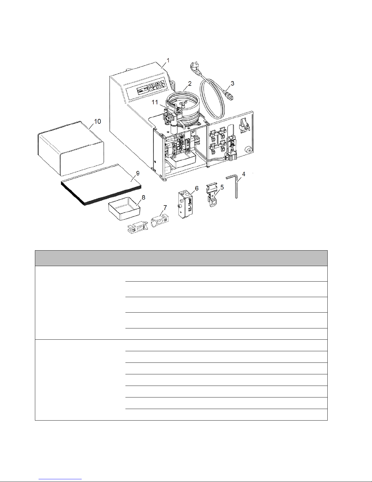
2.1 Scope of supply ................................................................................................................. 5
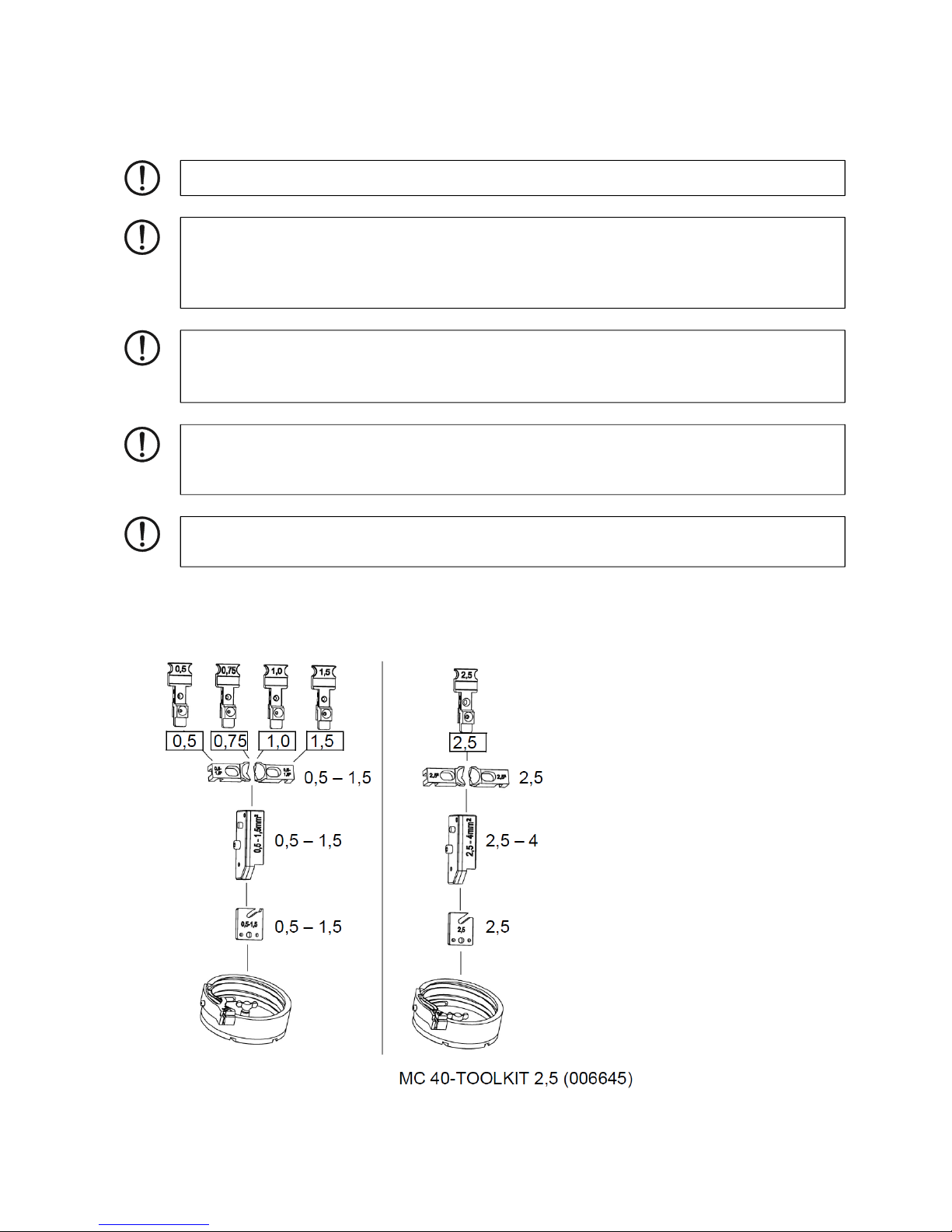
2.2 Suitable ferrules and retrofit kits ......................................................................................... 6
2.3 Overview of the operating components .............................................................................. 8
2.4 Control Panel ..................................................................................................................... 9
3 Starting up and operating ....................................................................................................... 10
3.1 Selecting the installation site ............................................................................................ 10
3.2 Determine the cross section............................................................................................. 10
3.3 Stripping and crimping ..................................................................................................... 11
4 Maintenance ........................................................................................................................... 13
4.1 Daily care ......................................................................................................................... 13
4.2 Adjusting and changing the stripping blade ..................................................................... 14
5 Retrofitting ............................................................................................................................... 16
5.1 Changing the cross section ............................................................................................. 1 6
5.2 Changing the crimping length .......................................................................................... 18
6 Troubleshooting ...................................................................................................................... 19
6.1 FC-2#0 does not run after being switched on .................................................................. 19
6.2 Start process is not being initiated ................................................................................... 20
6.3 Conductor insulation is not removed completely ............................................................... 2 0
6.4 Ferrule in-feed is disrupted .............................................................................................. 21
A Technical appendix .................................................................................................................. 22
A1 Technical data ................................................................................................................... 22
A2 EC Declaration of Conformity ............................................................................................ 23
A3 Spare parts ........................................................................................................................ 24

3
1 Basic information
For greater clarity, only the order designation FC-2#0 is used throughout this document.
For safe handling and trouble-free operation of the FC-2#0, you must be familiar with and observe the
safety notes.
1.1 Intended use
With the FC-2#0, you can either:
– Strip conductors automatically or
– Strip conductors automatically and crimp with ferrules.
Flexible conductors of class 2, 5, and 6 standard according to DIN VDE 0295 and ferrules
as loose products according to DIN 46228-4 are processed.
1.2 Work sites
WARNING: The FC-2#0 is intended solely for stripping and crimping.
In doing so, the conductor and ferrules with cross section or sleeve length according
to "Suitable ferrules and retrofit kits" on page 5 are to be used.
Only the PVC-insulated conductors may be inserted into the insertion funnel on the
FC-2#0 for processing. Under no circumstances should solid metal parts or other
similar objects be inserted. This damages the stripping blade.
Unauthorized conversions that exceed the scope of modification, and changes to the
FC-2#0 are not permitted for safety reasons.
NOTE: Correct usage includes observing all notes and complying with the
predefined operating conditions.
WARNING: The FC-2#0 may only be used
– as intended and
–
when in safe and fault-free condition.
WARNING: All persons responsible for commissioning, operating and maintenance
of
the FC-2#0 must
– be appropriately qualified and
– adhere strictly to this user manual.
NOTE: For operation and storage, avoid the following:
– humid or dusty places and
– locations exposed to high levels of heat, direct sunlight or low temperatures
(operating range: 15°C to 35°C)
NOTE:
If the machine is moved from a cold location to a warm location, condensation can
form.
• Before using the FC-2#0, open the front door and allow condensation to evaporate.

4
1.3 For your safety
For safety reasons, the FC-2#0 automatically switches itself off if the compressed air is
disconnected.
NOTE:
• Do not spill liquids on the FC-2#0.
• Do not expose the FC-2#0 to strong vibrations or shocks.FC-2#0 to strong
vibrations or shocks.
NOTE:
• Protect the compressed air hoses from heat, oil and sharp edges.
WARNING: The front door is installed for the safety of the operator. Under no
circumstances must it be modified, removed or bypassed using attachments.
WARNING:
• Only use filtered compressed air with a maximum pressure of 6 bar.
WARNING:
• Only operate the FC-2#0 when the front door is closed.
• Disconnect the mains plug and the compressed air plug prior to all work that
requires opening the front door (e.g., retrofitting, remedial action).
• Switch off the FC-2#0 and disconnect the device from the compressed air during a
break or when the device is not in use.
• Do not pull on the compressed air hose to disconnect the compressed air.
• Make sure that there are no foreign objects inside the housing.
WARNING:
• Before opening the housing, disconnect the mains plug and disconnect the device
from the compressed air.

5
2 Description of the FC-2#0
2.1 Scope of supply
Table 2-1 Scope of supply
Device Scope of supply
FC-200 and FC-250 Basic device
Mains cable
Waste box
Covering hood
Hexagonal wrench 4 5/32"
Only FC-200 Feeder bowl 0.5 ... 1.5 mm²
Separation plate 0.5 ... 1.5 mm²
Cord-centering funnel 0.5 ... 1.5 mm²
Reversing base sleeve 0.5 ... 1.5 mm²
Sleeve receiver 0.5/0.75/1.0/1.5 mm², 4 items
Crimping jaws 0.5 ... 2.5 mm² (≥ 12 mm crimping jaws)
Stripping blade with blade holder
1 Basic device
2 Feeder bowl
3 Mains cable
4 Hexagonal wrench
5 Sleeve receiver
6 Reversing base sleeve
7 Cord-centering funnel
8 Waste box
9 User manual
10 Covering hood
11 Separation plate
The components have
the same color-code as
the ferrules (according
to DIN color range)

6
2.2 Suitable ferrules and retrofit kits
With the FC-2#0, you can either:
– strip conductors automatically or
– strip conductors automatically and crimp with ferrules.
Flexible conductors of class 2, 5, and 6 standard according to DIN VDE 0295 and ferrules as loose
products according to DIN 46228-4 are processed.
The following loose ferrules can be processed with the FC-2#0:
Table 2-2 Suitable ferrules
Basic
device
Cross-
section mm2
Sleeve
length mm
DIN color
range
Comment Order No.
FC-200 0.25/0.34
0.25/0.34
6
8
yellow/
turquoise FC-2#0-TOOLKIT 0,34/ 6-8 006646
0.50
0.50
0.50
0.50
6
8
10
12
white
included in
FC-200
0.75
0.75
0.75
0.75
6
8
10
12
gray
1.00
1.00
1.00
1.00
6
8
10
12
red
1.50
1.50
1.50
1.50
6
8
10
12
black
2.50
8
10
12
blue FC-2#0-TOOLKIT 2,5 006645
4.00 10 gray FC-2#0-TOOLKIT 4,0/10 006650
FC-250 4.00 10
12 gray FC-250-TOOLKIT 4/10-12 006630
6.00 12 yellow FC-250-TOOLKIT 6-12 006813
10.00 12 red FC-250-TOOLKIT 10-12 006814
The FC-2#0 retrofit kit...-TOOLKIT.... is a case that contains
– Feeder bowl
– Reversing base sleeve

7
– Cord-centering funnel
– Sleeve receiver
– Separation plate
– Stripping blade (not required FC-2#0-TOOLKIT 2,5)
– Crimping jaws (not required FC-2#0-TOOLKIT 2,5)

8
2.3 Overview of the operating components
Figure 2-1 Operating components
1 Control
panel See page 7 for description 7 Manometer Display of the air pressure set
using the air pressure regulato
r
2 Feeder
bowl
Storage holder for ferrules 8 Water
separator
Container for condensation
3 Door lock Locks the front door. The front
door is opened by pressing the
lower segment and is closed by
pressing on the upper segment.
9 Drain valve For draining the water
separator
4 Insertion
funnel
The conductor is inserted through
the insertion funnel in the FC-2#0.
10 Mains
connection
Device connection for the
power cable with integrated
micro-fuse and switch, wide
range power supply unit
120 ... 240 V
5 Front door Protects the operator from moving
parts in the FC-2#0. The FC-2#0
only works when the front door is
closed.
11 Compressed
air
connection
Device connection to the
compressed air supply
6 Air
pressure
regulator
Setting the air pressure
Set the air pressure by pulling the
regulator upwards and turning to the
right (+) or left
(-).

9
2.4 Control Panel
Table 2-3 Button functions
Button Display Button function
Select operating mode
Strip only
For testing the incision depth of the
blade. The LED on the button lights
up.
Strip and crimp
The LED on the button lights up.
Changing the speed of the feeder bowl
Increases the speed of filling the feeder bowl
if new ferrules have been filled. Display
shows 100%.
The speed of the feeder bowl can be changed
using the arrow buttons. The speed is shown
in percent in the display.
2 s
Setting the counter to zero
Pressing the set/reset button for two seconds
resets the counter to zero.
5 s
Changing the counting direction
Pressing the set/rest button for five seconds
changes the counting direction. The counting
direction is shown in the display.
Forwards (1, 2, 3, ...)
Backwards (..., 3, 2, 1)
When counting backwards, a checkered flag
appears at
0 items. The device can no longer be started.
Turn the FC-2#0 off and on again. The FC-
2#0 changes to forwards mode.
Changing the counter reading with
backwards counting
Press the set/reset button briefly to change
the counter reading. The selected number
flashes.
The selected number can be changed using
the plus or minus button.
Another position within the five digit number
can be selected using the arrow buttons.
To save, press the set/reset button again.

10
3 Starting up and operating
3.1 Selecting the installation site
3.2 Determine the cross section
Check that the FC-200 is equipped for the desired cross section. If necessary, upgrade the
FC-200 (see "Retrofitting" on page 14).
Figure 3-1 Example of FC-200 (value in mm²)
NOTE: The device must be set up on a level and horizontal surface.
NOTE: For operation and storage, avoid the following:
– humid or dusty places and
– locations exposed to high levels of heat, direct sunlight or low temperatures
(operating range: 15°C ... 35°C).
NOTE: If the machine is moved from a cold location to a warm location,
condensation can form.
• Before using the FC-2#0, open the front door and allow condensation to evaporate.
NOTE:
• Do not spill liquids on the FC-2#0.
• Do not ex
p
ose the FC-2#0 to stron
g
vibrations or shocks.
NOTE:
• Protect the com
p
ressed air hoses from heat, oil and shar
p
ed
g
es.

11
3.3 Stripping and crimping
With the FC-2#0, you can either:
– Strip conductors automatically or
– Strip conductors automatically and crimp with
ferrules.
Checking the sleeve receiver
WARNING: Risk of injury!
Disconnect the mains plug and the
compressed air before you open the
front door.
• Switch off the FC-2#0 with the mains switch.
• Disconnect the mains plug.
• Disconnect the compressed air connection.
• Open the front door (1).
A Stripping
• Check that the sleeve receiver and litz wire
centering funnel are compliant for the
conductor cross section.
Modify if necessary (see page 14).
• Check whether sleeve receiver (2) is free from
ferrules.
B Stripping and crimping
• Check for the correct cross section setting.
Modify if necessary (see page 14).
• Fill ferrules into the feeder bowl (max. 500
pieces (FC-200)/max. 200 pieces (FC-250)).
• Close front door.
Aligning the conductor
• The conductor has to be aligned as straight as
possible before processing.
a) Bend is OK, maximum 2 – 3 mm at 6 mm
length
b) Bend too large
Cutting the conductor
• Cut the conductor off in a clean and straight
motion, for example
a) Proper cut
b) Cut surface angled
c) Cut surface squeezed, single conductors
pulled out
d) Cut surface squeezed

12
Connecting FC-2#0
• Connect compressed air connection (1) to the
compressed air supply.
• Check air pressure at manometer (2):
operating pressure 5 bar, at least 4.5 bar (FC-
200)
operating pressure 5.5 bar, at least 5 bar (FC-
250)
• Set air pressure, if necessary. Pull the air
pressure regulator (3) upwards, set the air
pressure by turning (4) to the right (+) or left (-)
and then press the regulator (5) downwards.
• Connect the mains plug to the FC-2#0 mains
connection and the shock-proof plug to the
mains socket.
Stripping conductors
A Stripping
Press the "Strip" button.
B Stripping and crimping
Press the "Strip and crimp" button.
Set the speed of the feeder bowl.
Wait until the ferrule is visible at the
separation plate (1).
A and B
• Insert the conductor straight into the insertion
funnel until it stops. As soon as the FC-2#0
starts, hold the conductor with slight tension.
The conductor is automatically stripped.
• When the FC-2#0 has stopped, pull the
conductor out.
Shutting down
• If necessary, read the counter and reset to
zero.
• Switch off the FC-2#0 with the mains switch.
FC-200: 4.5 bar ... 6 bar of
filtered air
In the event of a malfunction or
im
p
ro
p
er stri
pp
in
g
, see page 17.

13
4 Maintenance
4.1 Daily care
Cleaning FC-2#0
• Switch off the FC-2#0 with the mains switch.
• Disconnect the mains plug.
• Disconnect the compressed air connection.
• Open the front door (1).
• Empty the drawer (2).
• Clean the inside.
• Replace the drawer (3).
• Close the front door (4).
Checking the level of condensation
• Check the water level in the water separator
(1).
If water is in the water separator:
• Switch off the FC-2#0 at the mains switch (2).
• Disconnect the mains plug (3).
• Disconnect the compressed air connection (4).
• Store the container (5).
• Open the drain valve (6).
• Drain the water.
• Close the drain valve (7).
• Plug in the mains plug.
• Connect the compressed air connection.
WARNING: Risk of injury!
Disconnect the mains plug and the
compressed air before you open the
front door.
WARNING: Risk of injury!
Disconnect the mains plug and the
compressed air before opening the
drain valve.

14
4.2 Adjusting and changing the
stripping blade
Removing the stripping blade
• Pull the release lever (1) forwards.
• Remove the reversing base sleeve (2)
downwards.
• Pull the sleeve receiver (1) upwards, remove
from the holder (2).
• Slide the slide upwards and pull the holder (2)
forwards.
• Remove the second holder in the same way.
• Remove the cord-centering funnels (3) to the
left and right.
• Take out both the left and right stripping blades
(4).
• Worn-out or damaged blades must be
replaced.
• If the blades are still in working order, the
malfunction can be rectified by correcting the
incision depth on the right-side blade.
WARNING: Risk of injury!
Disconnect the mains plug and the
compressed air before you open
the front door.
WARNING: Risk of injury!
The stripping blades are sharp. Be
careful not to injure yourself.

15
FC-200: Changing the stripping blade
Left blade
• Unscrew the Allen screw (1) and take out the
old blade (2).
• Put new blade on the pin (3).
• Fix the limit plate (4).
• Tighten the Allen screw (1).
Right blade
• Unscrew the Allen screw (1) and take out the
old blade (2).
• Fix new blade.
• Loosen the Allen screw (5).
• Attach tappet over the groove (6) at the correct
incision depth (0 = initial position).
• Press the blade against the tappet and tighten
both Allen screws (1) and (5).
FC-250: Changing the stripping blade
• Unscrew the Allen screw (1) and take out the
old blade (2).
• Attach the new blade to the guiding pin (3).
• Adjust the incision depth of the stripping blade
to the conductor to be processed. Adjusting the
blade changes the incision depth by ±0.25 mm.
• Tighten Allen screw (1).
• Check incision depth by stripping a conductor.
The copper strands must not be cut by the
stripping blade.
WARNING: Risk of injury!
The stripping blades are sharp. Be
careful not to injure yourself.
WARNING: Risk of injury!
The stripping blades are sharp. Be
careful not to injure yourself.

16
5 Retrofitting
5.1 Changing the cross section
Preparing the modification
• Switch off the FC-2#0 with the mains switch (1).
• Disconnect the mains plug (2).
• Disconnect the compressed air connection (3).
• Open the front door.
Retrofit kits, see page 5.
Changing the feeder bowl
• Unscrew the winged screw (1)
• Move the feeder bowl to the side (2), pull
upwards (3) and empty.
• Attach the feeder bowl in such a way that it
slides into the centering pins and tighten the
winged screw.
Changing the reversing base sleeve
• Pull the release lever (1) forwards.
• Remove the reversing base sleeve (2)
downwards.
• Hold the release lever in the forward position
and attach the reversing base sleeve with the
desired cross section.
• Lock the release lever into place.
WARNING: Risk of injury!
Disconnect the mains plug and the
compressed air before you open
the front door.
FC-200: Change the feeder bowl
during a cross section change
from 0.5/0.75/1.0/1.5 ↔ 2.5
FC-250: Change the feeder bowl
every time the cross section is
changed.
NOTE: Ensure that all ferrules are
removed, especially from the slot
under the ba
f
fle.
FC-200: Change the feeder bowl
during a cross section change
from 0.5/0.75/1.0/1.5 ↔ 2.5
FC-250: Change the feeder bowl
every time the cross section is
changed.

17
Changing the sleeve receiver
• Remove the reversing base sleeve (see page
14).
• Pull the sleeve receiver (1) upwards, remove
from the holder and insert into the transport
holder (2).
• Insert the sleeve receiver into the holder using
the desired cross section (3) and push
downwards (4).
• Install reversing base sleeve.
Changing the cord-centering funnel
• Remove the reversing base sleeve and sleeve
receiver (see above).
• Slide the slide (1) upwards and pull the holder
(2) forwards.
• Remove the second holder in the same way.
• Remove both cord-centering funnels (3).
• Attach the cord-centering funnels onto the
driving pins (5) with the desired cross section
(4).
• Attach the holders (6) and press the slide (7)
downwards.
• Install the sleeve receiver and reversing base
sleeve.
Changing the stripping blade and jaws
• The steps for removing the cord-centering
funnels are mentioned above.
• Take out both of the stripping blades (1 + 2).
• Slide the cassette (3) upwards.
• Take out both of the crimping
The sleeve receiver must be
changed every time the cross
section is changed.
FC-200: Change the feeder bowl
during a cross section change
from 0.5/0.75/1.0/1.5 ↔ 2.5
FC-250: Change the feeder bowl
every time the cross section is
changed.
NOTE:Checkforcorrectlock‐inposition.
FC-200: No change.
FC-250: The crimping jaws and
stripping blade must be altered
durin
g
a cross section chan
g
e.
NOTE:Checkforcorrectlock‐inposition.

18
5.2 Changing the crimping length
Changing the separation plates
• Unscrew the separation plate (1) using the
hexagonal wrench and remove (2)
• Remove the separation plate from the retrofit kit
with the desired cross section and attach in
place of the previous separation plate.
Changing the crimping length
Changing the rotary dial
• Follow the steps mentioned above to remove
the stripping blade and crimping jaws (see
page 15).
• Insert the rotary dial (1) at the desired crimping
length using a screwdriver.
The selected value is shown via the red marker
(2).
• Re-attach individual parts.
FC-200: The separation plates
must be changed during a 0.5...1.5
↔ 2.5 cross section change.
FC-250: The separation plate must
be changed during a 4 ↔ 6 ↔ 10
cross section chan
g
e.
The crimping length is changed
using a rotary dial.

19
6 Troubleshooting
6.1 FC-2#0 does not run after being
switched on
Check the mains indicator
Mains indicator (1) is not lit:
• Check air pressure.
Mains indicator (1) is not lit:
• Check whether the mains plug is connected to
the FC-2#0 mains connection and the shock-
proof plug is connected to the mains socket.
• Check whether the power supply at the mains
socket is O.K.
• If O.K., check the mains fuse.
Check the mains fuse
• Switch off the FC-2#0 with the mains switch (1).
• Disconnect the mains plug (2).
• Pull out the fuse holder (3).
• Checking the mains fuse (4).
• Replace the defect mains fuse with the backup
fuse. Retrofit the backup fuse.
• Insert the fuse holder.
Check the air pressure
• Disconnect the compressed air connection (1).
• Check the air pressure at the manometer (2):
FC-200: 5 bar
FC-250: 5.5 bar
No pressure present:
• Check whether the compressed air connection
is connected to the compressed air supply.
• Check whether the compressed air supply is
O.K.
Pressure is not 5 bar/5.5 bar:
• Pull the air pressure regulator (3) upwards.
• Set the air pressure by turning (4) to the right
(+) or left (-).
• Then press the regulator (5) downwards.
WARNING: Risk of injury!
In order to check the mains fuse,
the mains connection has to be
open. Disconnect the mains plug
NOTE: The fuse holder should
snap into place.

20
6.2 Start process is not being
initiated
6.3 Conductor insulation is not
removed completely
Check cross section
• If the conductor isn't properly stripped, first
check that the FC-2#0 is fitted with the correct
retrofit kit.
If the conductor is inserted, the FC-2#0 will not
start.
Check the front door
• Check that the front door (1) is completely
closed and locked.
Check the air pressure
• Check air pressure at the manometer (1):
FC-200: 5 bar
FC-250: 5.5 bar
No pressure present:
• Check whether the compressed air connection
is connected to the compressed air supply.
• Check whether the compressed air supply is
O.K.
Pressure is not 5 bar/5.5 bar:
• Disconnect the compressed air connection.
• Pull the air pressure regulator (2) upwards.
• Set the air pressure by turning (3) to the right
(+) or left (-).
• Then press the regulator (4) downwards.
Check sleeve receiver
• Pull the release lever (1) forwards.
• Remove the reversing base sleeve (2)
downwards.
• Check that the sleeve receiver (3) is positioned
correctly and is snapped into place in the ball
latch.
• Install sleeve receiver.
• Close front door.
• Adjust the retrofit kit to suit the selected
conductor cross section (see page 14).
• Also check the conductor cross section.
• If the the malfunction continues despite having
the correct retrofit kit, check the stripping blade
(see page 12).
WARNING: Risk of injury!
Disconnect the mains plug and the
compressed air before you open
the front door.
This manual suits for next models
1
Table of contents
Other Artos Power Tools manuals