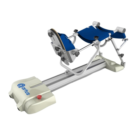
Artus ARTUS-301A User manual

User’s Manual
ARTUS-301A
Safety precautions are intended to protect the user's safety and prevent
property damage. Please read the instructions before use and use them
correctly.

CST. CO., LTD.
1
Contents
Chapter 1. Warning and Caution
1.1 Warning
1.2 Caution
1.3 Information of Electro-Magnetic Compatibility (EMC)
Chapter 2. Product
2.1 Introduction of
ARTUS-301A
2.2 Operation
2.3 Purpose of
ARTUS-301A
2.4 Before reading the user manual
2.5 Safety Precaution
2.6 Caution
2.7 Damaged product during delivery
2.8 Product Configuration
2.9 Label
2.10 Product specifications
2.11 Setting
Chapter 3. Explanation of Terms and Symbols
3.1 Explanation of Terms
3.2 Explanation of Symbols
Chapter 4. Operation
4.1 How to adjust the device according to the exercise
4.2 How to use hand controller and set the exercise
Chapter 5. Maintenance and Troubleshooting
5.1 Storage Conditions
5.2 Treatment and Maintenance
5.3 Troubleshooting
Chapter 6. Warranty
Thank you for purchasing theAnkle CPM(ARTUS-301A).
Please refer to the manual in the box to view the components contained within the box
when opening the box.
Be sure to familiarize yourself with this manual before connecting and powering down
the parts, and keep the manuals handy for future use.
The illustrations in this manual may differ slightly from the originals.

CST. CO., LTD.
2
Chapter 1. Warning and Caution
Safety precautions are intended to be used safely and correctly to prevent accidents or risks,
so please ensure that you read and protect them carefully.
Cautions are divided into ‘warning ’ and ‘ caution ’, each meaning :
Warning
:
If there is a possibility of death or serious injury to the person in violation
of the instructions
Caution
:
Violation of damaged products or possible minor injury to the human body
when violating the instructions.
1.1 Warning
Please check the power during installation and using.
Violation of this range could cause electric shock and product would be damaged.
Please check the wiring of all terminals before turning on the power.
This could cause electric shock and malfunction.
Please do not use it with wet hands.
This could cause electric shock and malfunction.
Please do not change or extend the power cable arbitrarily.
This could cause fires and electric shock.
Please program the range of motion as prescribed by a physician.
This could cause deterioration in affected area and injury.
Please do not place the product near the fire.
This could cause fires.
If there are any unusual sounds, smells and smoke from the product, please turn off the
main power switch. This could cause a fires and failure.
Please make sure to be careful of water inside the product.
This could cause fires and failure.
Please do not dismantle, repair and remodel arbitrarily.
This could cause fires and electric shock
Please do not keep the product with combustible substance and inflammability gas.
This could cause a fires and failure.
Please do not use the product in gas spill area.
This could cause fires and explosion.
Please turn off the power switch during cleaning.
This could cause fires and electric shock.

CST. CO., LTD.
3
1.2 Caution
Please do not disconnect the power or communication cables during operating.
This could cause injury.
Elderly people and people with disabilities should use it under supervision of product
manager such as doctor or physical therapist.
This could cause injury.
Please do not install the product on unsafe place.
This could cause injury.
Please do not dismantle the product arbitrarily.
This could cause fires and failure.
Please do not allow any metallic foreign substance to enter the inside of the product.
This could cause fires and failure.
Please connect the earth terminal.
This could cause electric shock, malfunction and failure.
Please clean the product with soft cloth and do not use strong cleanser like solvent.
This cause fires and deformation.
Please do not tap with anything sharp or use excessive force to the screen when using
the hand controller. This could cause damage the screen or malfunction.
Please check the tightening a bolt before operating.
This could cause injury.
Please avoid sharp object when installing and opening the product.
This could cause product damage.
Please make sure that a part of body or clothing gets caught to device during operating.
This could cause injury.
Please do not use except for rehabilitation treatment purposes.
This could cause failure and injury.
When you disconnect the power plug or hand controller, please hold the plug and
do not hold the cable.
This could cause electric shock and product damage.
Please disconnect the power plug from the socket before moving.
This could cause electric shock and product damage.
Please do not exercise too much.
This could cause injury of joints.

CST. CO., LTD.
4
1.3 Information of Electro-Magnetic Compatibility (EMC)
Warning : Please note that emitted electromagnetic signals from the external environment
may affect the patient and also ARTUS-301A.
Warning : Do not use ARTUS-301A near high-power wireless equipment such as mobile
phone, this could cause malfunction.
Caution : ARTUS-301A is compliant with medical device regulations 93/42 / EEC and it is
designed to protect it from electromagnetic signals.
Caution : Portable and mobile frequency (RF) communication device may affect the
electronic medical devices.
Caution : Only the component we provide are recommended to use, other unspecified
devices may cause increasing emissions and immunocompromised status.
The RF of “ARTUS-301A” emissions are very low and are not likely to cause interference
in nearby electronic equipment.
The “ARTUS-301A” is suitable for use in all establishments other than domestic and those
directly connected to the public low voltage power supply network that supplies buildings
used for domestic purposes.
Mains (AC) power quality should be that of a typical commercial or hospital environments.
Floors should be wood, concrete or ceramic tile. If floor is covered with synthetic material,
the relative humidity should be at least 30% to avoid excessive static electricity.
Warning : The “ARTUS-301A” should not be situated adjacent to, or stacked with,
other electronic equipment. If the system must be in installed in close
proximity to other equipment, both the “ARTUS-301A” and the nearby
equipment should be observed to verify normal operating in that
configuration.
Caution : The “ARTUS-301A” has been designed to meet the standards of
IEC60601-1-2 for electromagnetic compatibility; however some
computer equipment unintentionally emits strong interfering RF signals.
Portable RF communication devices may also affect “ARTUS-301A”.
Warning : Use of accessories other than those specified, may result in increased
emissions, or decreased immunity of this system.

CST. CO., LTD.
5
Chapter 2. Product
2.1 Introduction of ARTUS-301A
Thank you for purchasing ARTUS-301A.
ARTUS-301A is a rehabilitative exercise equipment (Continuous Passive Motion Machine)
that recovers the lost function of ankle joint quickly through the continuous passive motion
for patient who cannot exercise by themselves. It can also be adjusted to an upper and lower
angle limits and also it is available to program 5 steps exercising speed. Acceleration mode
allows the exercise speed up to 2 steps faster than previously programmed speed.
Hand Controller(H/C) which is adopting 3.5 inch screen and touch is easy to operate and it
provides the information of progressing and programing exercise on screen.
2.2 Operation
If it is left untreated after the ankle joint surgery, it may cause problems such as limited
range of motion and muscle contraction. And applying too much load to the ankle joint
without rehabilitation may worsen the condition of the surgical area. So it is necessary to
exercise properly for the quick recovery of surgical area. ARTUS-301A is the rehabilitation
equipment to recover the function of ankle joint quickly through continuous passive
movement.
Range of motion is different depending on the exercise mode and exercising ROM has to be
programmed according to the condition of patient.
Please exercise at a slow speed at first, and then do exercise higher speed and wider angle
after becoming familiar with the product. Exercise with a large range of motion from the
beginning could cause secondary damage to the patient's surgical site.
<FIG 2.1 ARTUS-301A>

CST. CO., LTD.
6
2.3 Purpose of ARTUS-301A
ARTUS-301A is a rehabilitative exercise equipment that recovers the lost function of
ankle joints quickly through continuous passive motion for patient who cannot exercise
by themselves at equipped such as hospitals.
The ARTUS-301A should be used in a properly equipped environment such as a
hospital and must be handled by trained professional who have the proper qualifications
like physical therapists or medical specialists.
2.4 Before Reading the user manual
Please read the user’s manual before using ARTUS-301A.
The user’s manual is for buyer and user, it will help to use the product safely.
The user’s manual is for using the product to ensure safe and proper use.
The user’s manual could be revised any time at the manufacturer's discretion.
2.5 Safety Precaution
ARTUS-301A uses the power of AC100V ~ 240V, 50 / 60Hz.
Please check the power when using it inside.
The product should be used while the room is at room temperature.
Please be well-informed of the user manual before using.
2.6 Caution
Please use the product as prescribed and do not stab the hand controller with anything
sharp.
2.7 Damaged product during delivery
ARTUS-301A will be shipped securely in an outer box with inner packing.
After receiving the product, please check for damage or something abnormal on product.
If any damage or abnormality is found, contact the company that purchased the product.

CST. CO., LTD.
7
2.8 Product Configuration
Please check the product and accessories before installation.
Main product
Hand Controller(H/C)
Power Cable
Component name
<Main Unit>
1) Calf support pad
2) Ankle motor
3) Footplate
4) Knee angle adjustment fixture
5) Ankle motor rotator
6) Rotator fixture
7) Frame
8) Connection for Hand controller
9) Power switch
10) Connection for power
11) Emergency Stop switch
<Hand Controller>
1) Touch screen : set the exercise
2) START button : start exercise
3) STOP button : stop exercise

CST. CO., LTD.
8
2.9 Label
H/C Label
2.10 Product specifications
Division
Contents
Type of Protection
Class I, Type B
Rated Power
AC 100V~240V, 50/60Hz
Power Consumption
40VA
Operating Temperature / Humidity
+10°C ~ +40°C / 80% or less
Storage Temperature
0°C ~ +60°C
Atmospheric Pressure
700~1060 hPa
Size
353 X 467 X 430 (Width X Length X Height)
Weight
9 kg
2.11 Setting
Division
Dorsiflexion / Planta flexion
Abduction / Adduction
ROM
Speed
1~5 step (75°/min~150°/min)
Pause time
0~9 sec
Timer/Counter
1~99 min / 1~99
Oscillation
Range of Angle : 5°~15°/ Repetition : 3~10
Progressive
Range of Angle : 5°~15°/ Repetition : 3~10
H

CST. CO., LTD.
9
Chapter 3. Explanation of Terms and Symbols
3.1 Explanation of Terms
Term
Explanation
Upper limit
Limit angle of flexion of ankle
Lower limit
Limit angle of extension of ankle
Upper pause
Pause time at Upper limit angle
Lower pause
Pause time at Lower limit angle
Progressive
Automatically and progressively increase the flexion and extension
angle until programmed angle.
Oscillation
Automatically oscillate at the flexion and extension angle by
programmed angle.
Bypass
The function of adjusting upper and lower limit angle during exercise
operating
Manual
The function to check manually the patient’s available exercising ROM
before exercise operating
Speed/Uni/Accel
Exercise speed level / Uniform speed / Accelerated speed
Timer
Time of Exercise
Counter
Number of Exercise
3.2 Explanation of Symbols
Symbols
Explanation
Exercise mode of Dorsiflexion / Planta flexion of ankle
Exercise mode of Abduction / Adduction of ankle
Increment / Decrement
Switching between program mode and exercise operating
mode / display of device operating status
Touch locked

CST. CO., LTD.
10
Chapter 4. Operation
Refer to 2.8 Product configuration.
Please review warning and caution in Chapter 1.
Please check the connection of the power switch (cord) and the hand controller.
Explanation of symbols in the control unit is covered in Chapter 3.
4.1 How to adjust the device according to the Exercise
Dorsiflexion/Plantaflexion Abduction/Adduction
(Locate ankle motor to the right side of device.) (Locate ankle motor to the front of device.)
4.1.2 For Abduction/Adduction of Ankle
(changing device setting to Abduction/adduction from Dorsiflexion/plantaflexion mode)
Step 1. Adjust the angle of the ankle motor by using the ‘Manual’ function of Hand
Controller(refer to clause 5.2.6) before changing the setting of the device to
make it easier to mount and separate the ‘f
ootplate(1)’.
Step 2. Separate the ‘footplate(1)’ from the ankle motor.
Step 3. Pull the ‘rotator fixture(2)’, and turn the ‘ankle motor rotator(3)’
counterclockwise to 90°until clicking sound appeared and ‘rotator
fixture(2)’ locked.
Step 4. Mount the connection guide under ‘footplate’ like above picture #4 to ankle
motor.

CST. CO., LTD.
11
4.1.3 For Dorsiflexion/Plantaflexion of Ankle
(changing device setting to Dorsiflexion/plantaflexion from Abduction/adduction mode)
※
Proceed in the opposite sequence from the method of clause 4.2.
Step 1. Adjust the angle of the ankle motor by using the ‘Manual’ function of Hand
Controller(refer to clause 5.2.6) before changing the setting of the device to
make it easier to mount and separate the ‘f
ootplate’.
Step 2. Separate the ‘footplate’ from the ankle motor.
Step 3. Pull the ‘rotator fixture’, and turn the ‘ankle motor rotator’ clockwise to 90°
until clicking sound appeared and the ‘rotator fixture(2)’ locked.
Step 4. Mount the connection guide on the side of the ‘footplate’ to the ankle motor.
4.1.4 Adjustment of the angle of knee
Step 1. Pull the ‘knee angle adjustment fixture(1)’.
Step 2. Lift up or push down the ‘calf support pad(2)’ as needed and fix it.
Warning : Make sure tighten the knob screw to prevent the device from being
loosen during exercise.

CST. CO., LTD.
12
4.2 How to use Hand Controller and set the exercise
4.2.1 Explanation of full screen
Function of each area
1) [Timer / Lower pause / Upper limit] area
Touch this area to set the exercising time, pause time at the lower
limit(plantaflexion/adduction) angle, and upper limit(dorsiflexion/abduction) angle to
exercise.
2) [Angle / Bypass / Manual] area
Touch this area to set Bypass, Manual function and display current exercising angle.
3) [Counter / Upper pause / Lower limit] area
Touch this area to set the number of exercising, pause time at the upper
limit(dorsiflexion/abduction) angle, and lower limit(plantaflexion/adduction) angle to
exercise.
4) [Up arrow / Down arrow] area
Touch this area to change a setting value and select a function.
5) [Exercise setting] area
Press and hold this area for 2 seconds to set the exercise.
6) [Speed / Uniform / Acceleration] area
Touch this area to set the exercising speed level and uniform or accelerative exercising
mode.
7) [Progressive / Oscillation ] area
Touch this area to select progressive or oscillating exercising mode.
8) [Touch Locked] symbol
This symbol means touch function being locked.
9) [M] symbol
Touch this area to save the set value and return to the previous screen at setting mode,
and it display exercise operating(circle of M is circulating) mode or stop mode.
<Touch and Display area>
1) Timer/Lower pause/Upper limit
2) Angle/Bypass/Manual
3) Counter/Upper pause/Lower limit
4) Up/Down arrow
5) Exercise setting
6) Speed/Uniform/Acceleration
7) Progressive, Oscillation
8) Symbol of Touch Locked
9) Exercise status

CST. CO., LTD.
13
4.2.2 Set the Exercise
Dorsiflexion / Plantaflexion
Abduction / Adduction
< Fig 4.2.1 >
※The name of each touch area refer to clause 4.2.1.
1) Press and hold [Exercise setting] display area(5) for 2 seconds to set the exercise,
when
the exercise symbol is flickering, select exercise using [Up/Down] arrow(4).
2) After selection of exercise, touch the [M](9) to save setting data.
4.2.3 Set the range of exercise and Pause time
※Refer to Fig 4.2.1.
1) Upper limit (angle) and Lower limit (angle)
●It means exercise range to do an exercise.
The upper limit angle means the max. angle of Dorsiflexion/Abduction.
The lower limit angle means the max. angle of Plantaflexion/Adduction.
●Touch the [Upper limit] display area(1), and select upper limit angle with [Up/Down]
arrow(4) when the number is flickering.
●Touch the [Lower limit] display area(3), and select lower limit angle with [Up/Down]
arrow(4) when the number is flickering.
● The upper limit angle has to be 5° larger than lower limit angle.
If this difference of angle is less than 5°, setting is impossible.
● And then, touch the symbol [M](9) to complete setting of rage of motion.
2) Upper pause (time) and lower pause (time)
●It is the exercise pause time at the upper or lower limit angle.
●[Upper pause] will be displayed when touched twice the [Lower limit] display area(3),
and select upper pause time with [Up/Down] arrow(4) when the number is flickering.
●[Lower pause] will be displayed when touched twice the [Upper limit] display area(1),
and select lower pause time with [Up/Down] arrow(4) when the number is flickering.
●And then, touch the symbol [M](9) to complete setting of pause time.

CST. CO., LTD.
14
4.2.4 Set the Exercising Speed and Uniform or Accelerative exercising
※Refer to Fig 4.2.1.
1) Exercising Speed
● It means operating(moving) speed of device.
● Touch the [Speed] display area(6), and select speed level with [Up/Down] arrow(4)
when the number is flickering.
●And then, touch the symbol [M](9) to complete setting of speed level.
2) Uniform(Uni) / Acceleration(Accel) mode
● Uniform(Uni) Mode : The device moves with uniform exercising speed in the ROM.
● Acceleration(Accel) Mode : The device moves by two steps faster than the
programmed speed in the middle 50% of the range of exercise.
●It is available to select uniform or accelerative exercising speed by touching twice
the [Speed] display area(6).
●The current selected mode is flickering and available to change that with
[Up/Down] arrow(4).
●And then, touch the symbol [M](9) to complete setting of this.

CST. CO., LTD.
15
4.2.5 Set the exercise time and the number of exercise
< Fig 4.2.2 >
※The name of each touch area refer to clause 5.2.1.
※If touch the symbol [M](9) at the screen of Fig 4.2.1, the screen is changed like
Fig 4.2.2.
1) Exercise time
●Touch the [Timer] display area(1), and change exercise time with [Up/Down] arrow(4).
●And then, touch the symbol [M](9) to complete setting of exercise time.
2) Number of exercise
●Touch the [Counter] display area(3), and change the number of exercise with
[Up/Down]
arrow(4).
●And then, touch the symbol [M](9) to complete setting of the number of exercise.
4.2.6 Set the function of Progressive and Oscillation
1) Progressive increasing of ROM
< Fig 4.2.3 >
●Until reached to programmed [Upper and Lower limit] angle, the function of
[Progressive] increase exercising angle progressively by 1°for each round trip of the
range of exercise.
●If touch the [Progressive, Oscillation] display area(6), the screen is changed to
Fig 4.2.3, [Progressive] is selected. If touched twice, [Oscillation] will be selected.

CST. CO., LTD.
16
●Touch the [Angle] or [Counter] display area, and change the angle or the number of
the [Progressive] with [Up/Down]arrow(4).
● [Angle] is the range of angle to be done the [Progressive] function at the Upper and
Lower limit. [Counter] is the number of repetitive movement every 1°increment.
●The range between the [Upper and Lower limit] angle should be 3 times larger than
the programmed [Progressive] angle.
●When the [Progressive] function is used, the [Upper and Lower limit] angle is adjusted
automatically if the programmed range between [Upper and Lower limit] angle is not 3
times larger than the programmed [Progressive] angle.
●With the [Progressive] angle is already programmed, if the range between [Upper and
Lower limit] angle is set to less than 3 times the [Progressive] angle, then the
[Progressive] function is automatically disabled.
●Setting example
●[Progressive] is disabled after completion of function.
2) Oscillation interval
< Fig 4.2.4 >
●When the device reaches the Programmed [Upper or Lower limit] angle, it will oscillate
between the programmed [Oscillation] angle.
●If touch twice the [Progressive, Oscillation] display area(6), the screen is changed to
Fig 4.2.4.
●Touch the [Angle] or [Counter] display area, and change the angle or the number of
the [Oscillation] with [Up/Down] arrow(4).
● [Angle] is the range of angle to be done the [Oscillation] function at the [Upper and
Lower limit]. [Counter] is the number of oscillation.
< Progressive Condition >
Upper limit angle : 50°
Lower limit angle : -50°
Progressive angle(PA) : 15°
Progressive Counter : 3

CST. CO., LTD.
17
●The range between the [Upper and Lower limit] angle should be 2 times larger than
the programmed [Oscillation] angle.
●When the [Oscillation] function is used, the [Upper and Lower limit] angle is adjusted
automatically if the programmed range between [Upper and Lower limit] angle is not
2 times larger than the programmed [Oscillation] angle.
●With the [Oscillation] angle is already programmed, if the range between [Upper and
Lower limit] angle is programmed to less than 3 times the [Oscillation] angle, then the
[Oscillation] function is automatically disabled.
●Setting example
※It is not available to use consequently both [Progressive] and [Oscillation].
4.2.7 Set the function of Bypass and Manual
1) Bypass
< Fig 4.2.5 >
●The [Bypass] function is used to adjust exercise range during exercise operating.
●Touch the [Angle] display area(2) while exercise is operating, [Bypass] is displayed
like screen Fig 4.2.5.
●When the motion is moving in the direction of [Upper limit] angle, pressing and
holding the [Up arrow] can increase current exercising angle over programmed
[Upper limit] angle. If it is reached at desired angle, touch [Upper limit] display area(1)
to change [Upper limit] angle.
●When the motion is moving in the direction of [Lower limit] angle, pressing and holding
the [Down arrow] can decrease current exercising angle over programmed
[Lower limit] angle. If it is reached at desired angle, touch [Lower limit] display area(3)
to change [Lower limit] angle.
< Oscillation Condition >
Upper limit angle : 50°
Lower limit angle : -50°
Oscillation angle : 15°
Oscillation Counter : 3

CST. CO., LTD.
18
2) Manual
< Fig. 4.2.6 >
●The [Manual] function is used to adjust exercise range at the stop mode.
●Touch the [Angle] display area(2) while exercise is stopped,
[Manual] is displayed like screen Fig 4.2.6.
●Pressing and holding the [Up arrow] increase current angle, if it is reached at
desired angle, touch [Upper limit] display area(1) to set as [Upper limit] angle.
●Pressing and holding the [Down arrow] decrease current angle, if it is reached at
desired angle, touch [Lower limit] display area(3) to set as [Lower limit] angle.
4.2.8 Locking the touch function
● It is possible to lock the touch function in order not to change a programmed value by
patient.
● Pressing and holding the [STOP] button for 5 seconds in the stop mode, the [Lock]
function is set with ‘beep’ sound and symbol displaying, above screen shows this.
●It is available to operate only [START] and [STOP] button.
●The [Lock] function is disabled with ‘beep’ sound and symbol disappearing by pressing
and holding the [STOP] button for 5 seconds.

CST. CO., LTD.
19
Chapter 5. Maintenance and Troubleshooting
5.1 Storage conditions
●Please shutdown the main power switch of the product before cleaning.
●Please use a dry cloth while cleaning to protect the inside of the product from liquid.
5.2 Treatment and Maintenance
●Please check the tightness of bolts on a regular basis, at least every six months.
●Please make sure that the cable is not damaged or torn.
● Please make sure that the label is not damaged and is kept to identifiable.
5.3 Troubleshooting
If you encounter any of the following problems during use, please do the following.
NO
Symptoms
Actions
1
The screen of the Hand
Controller does not work.
1. Please check the supplying of power.
2. Please check the connection of the Hand
Controller with device.
2
The touch function does
not respond.(no change/
no sound)
1. Please initialize the Hand Controller.
- Turn on the power again while pressing and
holding both of the [START] and [STOP]
buttons.
- When a screen is displayed, then touch
anywhere on screen.
2. Please check whether Touch Lock function
enabled. Refer to clause 4.2.7.
3
Error code ‘E1’ displayed
The motor is stopped temporary.
- Please check the cable connection between
Hand Controller and Device.
- If the Hand Controller cable is disconnected to
device, please reconnect the cable after power
turn off.
4
Error code ‘E5’ displayed
The current angle is out of programmed range of
exercise.
- Pressing and holding the [START] button for
more
3 seconds, then the device goes into
the programmed range.
The error code will disappeared.
5
Error code ‘E9’ displayed
The emergency stop button on device was pressed.
- When the emergency stop switch is released by
turning clockwise, the error code will disappeared.
Table of contents
Other Artus Medical Equipment manuals