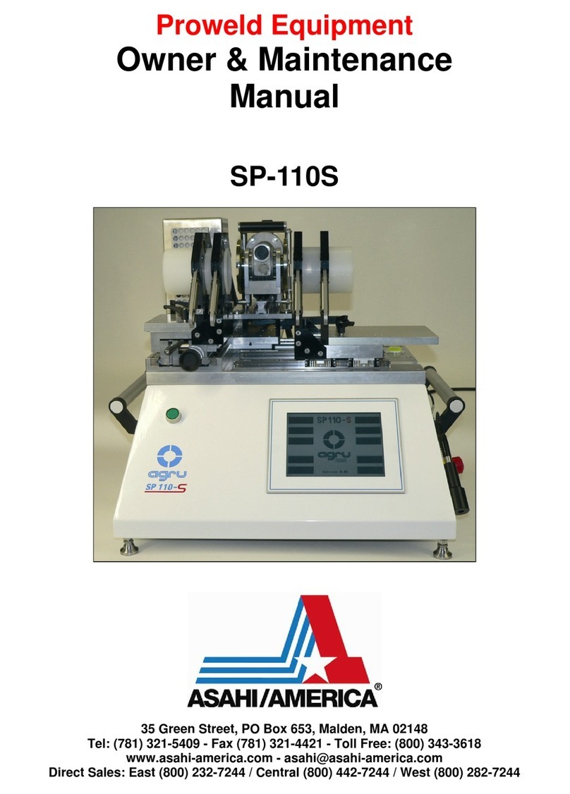
Asahi/America agru SP 110-S V3 User manual

Tel: 781-321-5409 ● Fax: 800-787-6861 ● Toll Free: 800-343-3618
www.asahi-america.com ● asahi@asahi-america.com
Direct Sales: East 800-232-7244 / Central 800-442-7244 / West: 800-282-7244
User’s Manual
SP 110-S V3
High Purity IR Welding Tool

PAGE LEFT INTETIONALLY BLANK.

Version September 2017 EN 3
agru SP 110-S V 3 User’s Manual
Contents
1 Introduction ...........................................................................................................5
2 Safety Messages...................................................................................................5
2.1 The User's Manual ................................................................................................5
2.2 Explaining Icons ....................................................................................................5
2.3 Safety Messages and Information on Residual Risks...........................................6
2.4 User/Operator Obligations ....................................................................................7
2.5 Worksite Description .............................................................................................7
2.6 Warranty................................................................................................................7
2.7 Transport and Storage ..........................................................................................7
2.8 Identifying the Machine .........................................................................................8
3 Product Description and Principles of Operation ..................................................8
3.1 Intended Use.........................................................................................................8
3.2 Machine Description..............................................................................................8
3.2.1 Component Overview............................................................................................9
3.2.2 Touchscreen / Control Panel .................................................................................9
3.2.3 Ports and Switches .............................................................................................10
3.2.4 Speci¿cations ......................................................................................................10
3.3 Welding Process Overview .................................................................................10
4 Operation ............................................................................................................11
Stowing the Machine in the Transport Box..........................................................12
4.1 Check-out, Turning on, Selecting the Display Language ....................................13
4.2 Con¿guring the Machine .....................................................................................14
4.3 Fully Automatic and Semi-automatic Operation ..................................................16
4.4 Changing Key Parameters of the Welding ..........................................................17
4.5 Entering Traceability Data for the Joint ...............................................................18
4.6 De¿nition of Welding Parameters for Additional Materials ..................................18
4.7 Welding Process .................................................................................................19
4.7.1 Facing the Component Butts, with or without Prior Alignment of the Components 19
4.7.2 Checking Pipe Alignment ....................................................................................21
4.7.3 Pre-heating the Pipe Butts and Inserting the Heating Element...........................21
4.7.4 Heating Stage .....................................................................................................22
4.7.5 Change-over Stage .............................................................................................22
4.7.6 Joining Stage ......................................................................................................22
4.7.7 Cooling Phase.....................................................................................................22
4.7.8 End of Welding....................................................................................................23
4.7.9 Assessing the Joint by a Visual Check at the End of Welding ............................23
4.8 Aborted Welding Process....................................................................................24
4.9 Indication of Joint Status and Possible Errors on the Tag...................................26
5 Printing Pipe Labels and Downloading Welding Reports....................................26
5.1 Downloading Welding Reports to a USB Stick....................................................27
5.2 Showing Reports in Memory, Printing Pipe Label Tags.......................................27
5.3 Using the Extended Report Viewer .....................................................................28
5.3.1 Viewing the Full Welding Report .........................................................................29
5.3.2 Ongoing Job Reporting Scheme and Statistical Overview..................................29
5.4 Deleting Reports from Memory ...........................................................................29
6 System Data........................................................................................................29
6.1 System and Maintenance Information.................................................................29
6.2 Enabling Automatic Heating ................................................................................30
6.3 Service and Repair..............................................................................................30
7 Service and Repair Contact ................................................................................31
7.1 Manufacturer Warranty........................................................................................31
7.2 Technical Documentation ....................................................................................31
7.3 Risk Assessment.................................................................................................31
Asahi/America Contacts.......................................................................................32

Version September 2017
4EN agru SP 110-S V3 User’s Manual
Caution
The machine has to be operated exclusively with
a power supply line equipped with a protective
grounding conductor, as a power supply without
this safety element may cause severe machine
damage. If the machine is operated through a
power supply without a grounding conductor,
this will void any and all warranty under which
the product may be.

Version September 2017 EN 5
agru SP 110-S V3 User’s Manual
1 Introduction
Dear Customer:
Thank you very much for purchasing our product. We are confident that
it will meet your expectations.
The development, manufacture, and check of the infrared welding
machine has been guided by our concern to offer a unit characterized
by superior operation safety and user-friendliness. The unit was
manufactured and checked according to the most recent standards as
they are applied, and bearing ergonomic aspects in mind.
To ensure maximum operation safety, please conform to the appropriate
messages in this booklet and the regulations for the prevention of
accidents. Carefully read the User’s Manual to avoid damage to the
machine or hardware in its environment as well as injury.
This manual is applicable to the following machines:
agru SP 110-S V 3
Thank you.
2 Safety Messages
This User’s Manual contains important instructions for operating the infra-
red welding machine agru SP 110-S V 3 safely. Every person who operates
the machine will have to conform to the instructions of this manual.
The machine has been developed and checked with respect to welding
agru materials. For welding other makes, no experiential data are avail-
able and/or no liability or warranty can be assumed for the fitness and
the reliable operation of the machine.
2.1 The User's Manual
The User’s Manual is presented according to sections which explain
the different functions of the machine. All rights, in particular the right to
copy or reproduce (in print or electronic form) and distribute as well as
to translate, are reserved and subject to prior written authorization by
agru Kunststofftechnik.
2.2 Explaining Icons
The following expressions and icons are used in this User’s Manual to
refer to safety-related issues:
Caution
Important
Info
This icon indicates that non-compliance may result in a
hazardous situation that possibly causes bodily injury or
material damage.
This icon indicates important messages related to the correct
use of the machine. Non-compliance may cause problems of
operation and damage to the machine.
This icon indicates tips and useful information for using the
machine more efficiently and more economically.

Version September 2017
6EN agru SP 110-S V3 User’s Manual
2.3 Safety Messages and Information on Residual Risks
Protect the power supply cord from cutting edges. Have an authorized
service shop replace damaged cables or lines immediately.
The machine has to be operated with a 230 V, 50/60 Hz power supply with
safety fuse or breaker of 16 A maximum. If power is connected through
a power line manifold, the power supply has to feature an earth-leakage
circuit breaker.
The length of the power supply cord must not exceed 10 m (30 feet) from
the circuit breaker.
Caution
Caution
Caution
Caution
Caution
Important
Important
Info
Parts Under Power
After opening the machine or removing the cover, parts of it
are accessible that may be under power. The machine may be
opened exclusively by an authorized service shop.
Pipe Facing Tool
Start the pipe facing tool only when it is in its working position.
When facing pipes, do not wear jewelery; if needed, wear a
hair snood or net. It is forbidden to remove shaving from the
machine while the facing process is running. Make sure nobody
is present in this danger zone.
Heating Plate and Heating Plate Housing
When working with the machine, be extremely cautious while the
heating plate is operating. Since the plate and its housing guard
present a very high temperature during the welding process, it
must not be operated if unobserved, and sufficient distance to
combustible materials in its surroundings has to be ensured.
Do not touch the heating plate or the plate housing. The safety
alerts affixed to it have to be complied with strictly.
Danger of Bruises and Injury
Do not remain in the danger zone while the machine opens or
closes and be sure not to have your hands between the moving
and the fixed parts of the machine.
Acceptable Work Conditions
The work zone has to be clean and has to have proper lighting.
It is dangerous to operate in a humid environment or close to
flammable liquids. In regard of this, acceptable work
conditions have to be ensured (e.g., sufficient distance
between the machine and other functional areas of the
workshop).
Power Supply Only through Line with Protective Grounding
Conductor
The machine has to be operated exclusively with a power supply
line equipped with a protective grounding conductor, as a power
supply without this safety element may cause severe machine
damage. If the machine is operated through a power supply
without a grounding conductor, this will void any and all
warranty under which the product may be.
Power Only to Operational Machine
Power must never be applied to the machine before it is com-
pletely installed and ready for operation.
User’s Manual
The User’s Manual has to be available at any time on the site
where the machine is used. If the User’s Manual should come

Version September 2017 EN 7
agru SP 110-S V3 User’s Manual
to be incomplete or illegible replace it without delay. Feel free
to contact us for assistance.
2.4 User/Operator Obligations
• The machine may be operated exclusively by persons who are
familiar with the applicable rules, the guidelines for the prevention
of accidents, and the User’s Manual.
• The machine may be operated only when observed. Only persons
who were properly trained by agru or another, authorized
organization and whose training was acknowledged by the
appropriate certificates are allowed to operate and observe the
machine. Other persons must neither operate nor observe it.
•The operating/owning organization engages to check at reasonable
intervals if the machine is operated by the users with the intended
use and under proper guidelines of safe work.
• The machine must never be operated if not in proper state of repair.
Before welding, the user is required to make sure that the state of
the machine is in order.
• The user has to make sure that only one person is present in the
zone where the machine is operating.
2.5 Worksite Description
• The conditions have to fully ensure that the machine cannot slide
if it is not used standing on the box and stand on which it ships.
•Worksite access limitations have to be provided. Appropriate
equipment to achieve this can be requested from a service point
or the selling entity.
•The machine has to be positioned so it will not be exposed to
droughts. When used in clean rooms, do not position it directly below
any air inlets (laminar flow).
2.6 Warranty
Warranty claims may be raised only if the conditions for warranty given
in agru Kunststofftechnik’s General Terms and Conditions of Sale and
Shipment obtain. Furthermore, the provisions and instructions contained
in the User’s Manual have to have been respected.
Info
The term of warranty under which the welding machine is
shipped is 12 months:-
— from the date of purchase, if machine bought as new
—machine;
— from the date of first use, if machine used independently of
—purchase (e.g. when lent) or not bought as new machine.
2.7 Transport and Storage
During transport, the machine must be at all times in the transport box
it is shipped in.
Important
Ensure that the heating plate is locked during transport at all
times.
The transport box should also be used to store the machine. The machine
has to be stored in a dry location, be clean or has to be cleaned, and be
locked against unwanted operation.
Caution
The weight of the machine is 115 kg (253 lbs). Because of this
heavy weight, transporting the machine or moving it on site
requires appropriate hoisting tools. Using the machine, as far
as possible, only standing on its stand which doubles as a
storage box is highly recommended.

Infrarot-Stumpfschweißmaschine
Typ agru SP 110-S V 3
Geräte-Nr. 11310209
Netz 230V 50Hz 2300W IP54
Gewicht 115kg Baujahr: 2017
Lizenzhersteller
HÜRNER Schweißtechnik GmbH
Nieder-Ohmener Str. 26
D - 32325 Mücke
Typ agru SP 110-S V 3
Exklusives Produkt der Fa.
agru Kunststofftechnik GmbH
Ing.-Pesendorfer-Str. 31
A - 4540 Bad Hall
Tel. +43 7258 790 3503
Fax +43 7528 790 3852
Version September 2017
8EN agru SP 110-S V3 User’s Manual
2.8 Identifying the Machine
Each machine is identified by a name plate. It shows the machine
model (“Typ”), its year of manufacture (“Baujahr”), the serial number
(“Geräte-Nr.”), the rated power (“Netz”), and the manufacturer (“Lizenz-
hersteller”).
3 Product Description and Principles of Operation
3.1 Intended Use
The agru SP 110-S V3 Welding Machine is designed exclusively for
welding plastic pipes and fittings using the infrared welding technique
(butt welding without contact).
Only the welding parameters shown on the touchscreen display
(preprogrammed by the manufacturer or defined by the user) can be
selected for awelding operation. Any modification of the welding
parameters contained in the control software is strictly prohibited.
The notion of intended use also includes compliance with the instructions
provided in the User’s Manual.
Important
The manufacturer can in no circumstances be held liable for
damage or consequential damage that occurs as a result of the
non-compliance with the procedures described in the User’s
Manual, the modification of the manufacturer-programmed
welding parameters, or non-intended use. Any such deviation
or modification will void any and all warranties under which the
product may be.
3.2 Machine Description
The machine can be used as an in-shop installation, and with anodized
aluminum components, it is also suited for clean room applications.
The machine enables users to enter the data that are relevant for the
welding process and for the traceability of the welded joint. From the
entered welding parameters, it calculates the applicable forces and
temperatures and controls the welding process automatically.
The machine is designed, manufactured, and equipped in such a way
that there is little need for the user to influence upon the process.
All welding and traceability data are entered either directly on a
touchscreen panel or read from a transponder card by the RFID
reader. The welding process in monitored in its entirety and saved to a
welding report. All welding reports can the be downloaded to a USB stick
as an abstract, an extended report or as an AGRU WELD NET
database file.
Using the menus displayed on the touchscreen, the machine can be
customized to the application in hand (see section 4.2, Configuring the
Machine).

Version September 2017 EN 9
agru SP 110-S V3 User’s Manual
3.2.1 Component Overview
3.2.2 Touchscreen / Control Panel
Status Bar
Title Line
Multifunctional Area
(changes
depending on context of display)
- Display of/data on welding
progress
- Parameter menus to
configure operation settings
- Input keyboards
- Error messages/Notes
Navigation Bar with User
Interface Buttons
(changes depending on
context of display)
Heating Element and Guard Housing
Facing Tool
Fixed and Mobile Carriage of
Machine, Each with Two
Component Clamps
Emergency Off Switch
Touchscreen Panel under
Plastic Impact Cover
Pushbuttons to Perform Machine
Movements in (Two-hand) Fully
Automated Mode
RFID Reader
Set Screws for Compensation of
Small Horizontal or Vertical Alignment
Gaps
Ambient Temperature
Sensor
Heating Element under Part of the
Guard Housing Moving with It
Facing Tool
Dual Level for Bidirectional Levelling
Fixed Part of Heating Element Guard
Housing, Fastened to Machine
Enclosure

Version September 2017
3.2.3 Ports and Switches
3.2.4 Specifications
agru SP 110-S V 3
Power Characteristics
Voltage
Frequency
Total Rated Power
Heating Element
Facing Tool
230 V
50/60 Hz
2.30 kW
1.60 kW
0.35 kW
Welding Operation Specs
Welding Force
Speed of Facing Tool
Ambient Temperature (operation)
Ambient Temperature (storage)
Operating Range
10 - 500 N
approx. 45 rpm
+10°C to + 40°C (50°F to 104°F)
–5°C to + 50°C (23°F to 122°F)
Diameter 20 - 110 mm (3/4" - 4-1/3")
Dimensions and Weight
Dimensions (W x D x H)
Mach. in the transport box (closed)
Machine in the transport box (open)
Machine only
Weight
Maximum Carriage Stroke
790 x 950 x 1320 mm
(31
7
»
64
" x 37
13
»
32
" x 51
15
»
16
")
790 x 825 x 1280 mm
(31
7
»
64
" x 32
15
»
32
" x 50
7
»
16
")
585 x 785 x 630 mm
(23
1
»
32
" x 30
15
»
16
"" x 24
7
»
8
")
115 kg (253 U.S. lbs.),
in box approx. 245 kg (539 U.S. lbs.)
approx. 146 mm (5¾")
3.3 Welding Process Overview
The welding process is performed as follows:
• Components are clamped into the frame; depending on the form of
the component to be welded, this may mean that the outer clamps
have to be re-adjusted or that reducer inserts have to be inserted.
• Pipe ends are worked using the facing tool until the machine
indicates facing completed, to be confirmed on the touchscreen; then
removal of chips and shavings (vacuum cleaner recommended).
• Pipe alignment is checked and confirmed on the touchscreen.
10 EN agru SP 110-S V3 User’s Manual
Connector for Power
Cord to Label Tag
Printer
Buzzer
USB Interface Port
On/Off Switch and
Power Supply Connector
Caliper
Connector
Pushbuttons to
Perform Machine
Movements in Semi-
or Fully Automated
Mode

Version September 2017 EN 11
agru SP 110-S V3 User’s Manual
• Automatic insertion of the heating element; when inserting it, the
heating element has to be clean.
•After the heating element was inserted, the pipes close in
automatically at the predefined force.
• When the movable carriage closes in, this also aligns the heating
element exactly in-between the pipe butts.
•At the same time, the pipe butts are heated to the predefined
temperature.
•The following steps in the process are performed in a fully automated
fashion by the welding system:
• After the full heating time, the heating element is removed.
• For the fusion stage, the movable carriage closes back in.
• The fusion force is applied as a linear force increase.
• The new joint then cools down at the predefined force.
• After the cooling time is over, the force is automatically removed
from the carriages and the pipe or fitting can be taken out of it.
• The user enters an assessment of the quality of the joint, possibly
after measuring the bead with the optional electronic caliper.
4 Operation
Before putting the machine into operation, review the transport locks and
safety auxiliaries as well as the way the machine is set into the upper area
of the transport box. Whenever the machine is moved or shipped, it has
to be set into this box and all locks and auxiliaries have to be engaged.
The figures below help with understanding the transport helpers.
After these photos, you will find a description of how to stow the machine
safely at the end of work. Taking the machine out of the box and putting
it into operation — including first check-out after delivery — will be done
be performing the same steps in reverse order.
Handle for Carrying Box
Machine with Engaged
Transport Locks in Upper
Part
Latch for Securing Upper to
Lower Part of Box
Drawer for Accessories
Drawer for Label Tag Printer
Drawer for Reducer Inserts

Version September 2017
12 EN agru SP 110-S V3 User’s Manual
Inside view of the drawer for the
reducer inserts
Transport Lock (four units, one per leg of
machine); dogs slide around leg and outer
screw; when screws loosened, dog bar swivels
around inner screw, releasing leg; when machine
used standing on the lower part of the box,
transport locks can remain installed.
Transport Lock of Console
Carrying Facing Tool and Heating
Element: installed in rail during
transport, “parked” on enclosure
frame during operation
Transport lock of the
heating element; locking/
unlocking according to
the principle of a ratchet
screwdriver, to turn the
lever back without
engaging the thread, lift
it slightly
Important
When the printer is moved or shipped, the roll of labels in the
printer has to be removed
Important
To install the transport lock for the console carrying the facing
tool and the heating element, the machine has to be switched
off and the console has to sit as far to the right (looking on the
machine from behind) as it will go.
Info
When installing the reducer inserts, place the narrower inserts
into the inner clamps, the broader inserts, into the outer clamps.
The insertion and the removal of the inserts is performed with-
out any tools and the reducers are secured to the clamps by
the force of the magnets only.
Stowing the Machine in the Transport Box
• Switch the machine off, clean it, and remove all accessories and
cables and put them securely into the respective drawers in the
lower part of the transport box. If the machine is/was used standing
on the lower part of the box, the cables connecting it to the label
printer can remain.
•Take the reducers out of the clamps and put them into the drawer
provided to this end.
•Install and lock the transport locks (heating element, console carrying
the facing tool and heating element) (see drawings at the beginning
of this section for reference).
•Unplug the power cord in and, e. g. using a Velcro strap, stow it
securely.
•With the help of the carrying handles, lift the machine onto the
lower part of the transport box and engage the four transport locks
at its legs, unless the machine was used secured for transport and
standing on the lower part of the box.
•Install the upper part of the transport box and close the box by
installing its front, securing everything by engaging the various
latches between the parts of the box.
Power supply connector of the heating element with
fastening clip; the fastening clip should always be, and has
to be, engaged during operation
Power supply and USB connectors for
label tag printer when this is used
standing in the printer drawer

ýeský
Nederlands
Italiano
Español
Deutsch
Trad.Chinese
茬豬譄芉
Korean
穢剳檺
Arabic
ϰΑήϋ
Russian
Ɋɭɫɫɤɢɣ
Svenska
Français
English
Japanese
襲莇蛑
Simp.Chinese
এѽИކ
Version September 2017 EN 13
agru SP 110-S V3 User’s Manual
4.1 Check-out, Turning on, Selecting the Display Language
Place the machine on its stand which is part of the transport box or on
a level surface where it cannot slide, at a distance to other areas in the
workshop, especially to those in which combustible materials are used,
that is sufficient in order for the heating element temperature of up to
500°C (930°F) not to be hazardous. When starting the machine up,
remove the transport locks before applying power to the machine if it was
transported before start-up and the locks were engaged. Furthermore, if
the electronic caliper and the label tag printer are planned to be used later
on, connect them to the machine before the first welding operation.
Info
If the machine is going to be used not standing on its own, but
on the lower part of the transport box, the label printer remains
in the storage drawer and is connected to it via the external
ports on the box (see drawings at the beginning of Sect. 4).
Depending on the piece that is going to be welded, the outer clamps may
have to be repositioned or removed. To do so, loosen the locking bolts
and either remove the clamp or re-adjust it and secure it by tightening
the locking bolts again. The carrying plate of the outer clamps on both
sides are interchangeable. If you install the one normally on the right on
the left-hand carriage of the machine and vice versa, you increase the
distance between both clamps on both sides of the machine.
If the diameter of the pieces to be welded is smaller than the clamp, insert
the reducer inserts. This can be done without using any tools since the
inserts are fastened in the clamps by magnetic attraction.
Important
Pipe clamps and reducer inserts have to be clean or must be
cleaned before welding starts. To insert or remove the inserts,
do not use heavy tools (hammer, wrench). They may damage
the inserts and the magnets.
Important
Make sure that all parts to be jointed are dual-clamped and/or
appropriately supported.
Important
The surfaces of the heating plate have to be free of grease and
clean, or they have to be cleaned. Clean the heating element
only when it is cold. Refer to a service point for detailed infor-
mation on the procedures for cleaning the heating element.
Important
Make sure all connectors are tight in their sockets and make
sure that the machine is operated only if the conditions for safe
and intended use are met (see also section 2).
After preparing the machine for welding and
connecting the power supply cord to mains
power, the machine is turned on using the On/
Off switch. The welcome screen, as reproduced
in Display 1, appears on the touchscreen panel.
Touch the ap-propriate button to select the display
language that the machine will use. If needed,
the system clock will then have to be set, in which
case the relevant screen is displayed (see
Display 26).The machine then takes the user to the
welder code
input screen. Without a valid welder identification code, it is impossible
to start welding processes on the machine. The next automatic step at
power-up, after welder code input, is the zeroing of the movements.
Without successful zero point of reference calibration, the heating
element will not heat up for welding.
Display 1

Version September 2017
14 EN agru SP 110-S V3 User’s Manual
Enter the welder identification code by typing it on the touchscreen and
saving it to memory by touching the button. If a transponder card
for the welder code is available, you can also read it from it by RFID.
Info
Important
With the exception of the welding pa-
rameters (see Sect. 4.4) and the
customized parameter sets, all inputs
for which a transponder card is
available can be entered by holding
the card in front of the RFID reader.
Entering data on the touchscreen must
always be performed with the
bare finger. Using objects (ballpoint
pens, screwdrivers, etc.) may
cause unre-coverable damage to the
surface of the touchscreen.
Info
Depending on the software version installed in your machine,
some screens may differ slightly on your machine from the
reproductions in this manual.
After welder code input and zero point calibration, the machine displays
the first input screen of the welding process proper (see Display 3). In
this display, it is possible to start the welding process and to customize
the configuration of the machine.
The welder will enter all settings and perform all control actions on the
touchscreen panel.
4.2 Configuring the Machine
In the first input screen of the welding process
proper (Display 3), the parameters of the last
welding are shown (product/component, material,
diameter, wall thickness, and SDR value of the
processed component). Furthermore, the status
bar at the top of the screen shows the date, time
of day, and also the registered welder and the
machine identification.
In Display 3, the welder has the possibility to:
• immediately start a welding process that will
be performed with the same welding parameters as the previous
welding (touch the button and move on to section 4.7);
• enter new component-related and traceability data for the next weld-
ing (touch the button and move on to
sections 4.4, 4.5);
• change the machine settings in the configura-
tion menu (touch the button);
•display information on the welding system
itself and its maintenance/service status
(touch the button and see Sect 6.1 for
reference);
•view the operator’s guidelines for the jointing
of thermoplastic components (touch the
button; see Display 4 for reference);
•lock the machine against unwanted
•manipulation by holding down both
pushbuttons starting machine movements until the welder code
input screen ap-pears and a valid welder code is required to
unlock the machine
Display 4
Display 3
Display 2

Version September 2017 EN 15
agru SP 110-S V3 User’s Manual
• enter a new welder code by holding a transponder card into the read
range of the RFID reader.
To access the configuration menu, press the button. Some options
of the menu are protected by a code called selection code. Therefore,
when browsing from one page to the next in the menu, you may be
prompted to enter this code in a screen resembling Display 2, where it
has then to be confirmed by the button. The menu has the items
listed in the following table.
In the menu, the button depicted at an option means that touching it
will open a submenu in which the configuration itself can be customized.
For functions that the user can enable or disable at their own discre-
tion, the (on) and (off) buttons indicate the current status.
Touching the button will toggle the function from one to the other state.
Use the arrow buttons pointing to the left and to the right to move back
to the previous or on to the next page of the menu.
Designation Setting Description / Data to be entered
Report View In a sub-menu, a welding operation can be selected in a list to
display the report recorded of that operation. From this screen, it is
also possible to print a label tag for this welding once again (see
section 5.2).
Select Number of
Labels
In a sub-menu, the number of label tags (0 - 3) to be printed after
welding for purposes of identification, can be selected.
Select Unit of Length In a sub-menu, the unit of length used for displaying welding data
can be selected: millimeters or inches.
Select Temperature
Unit
In a sub-menu, the temperature unit used for displaying welding data
can be selected: centigrade or degrees Fahrenheit.
Buzzer if ON: The audible signal that validates certain steps in the process
is turned on;
if OFF: At the end of the respective steps no signal can be heard.
Set Volume of
Buzzer
In a sub-menu, the volume of the audible signal that the machine
emits to validate the execution of a given step in the process can be
set.
Automatic Heating In a sub-menu, a time, for instance on the following morning, can be
pre-set when the heating element will start heating up automatically
(see sub-section 6.2).
New Report View if ON: The Report View option of the menu calls an extended and
more powerful report view, which allows in-depth assessment and
analysis (this report view requires entering a Supervisor Code that
authorized persons, e. g. a project manager, can set and enter
themselves);
if OFF: The Report View option of the menu calls the standard, less
detailed report view of welding operations (this report view is also
displayed if the option is enabled, but the entered access code for
the new, extended report review is entered incorrectly).
Bead Dimensions if ON: At the end of the welding process, the machine requires the
welder to measure the dimensions of the welding bead with the
electronic caliper as an assessment of the quality of the joint (see
Sect. 4.7.9);
if OFF: At the end of the welding process, the machine only requests
a visual check of the bead by the welder.
The functionality will be disabled automatically during a welding
operation, even when it is enabled in the menu, if no bead
dimensions exist in memory for reference for the parameters of that
particular welding operation.
Bead Force while
Welding
if ON: During welding, the diagram depicted on the screen
represents the force exercised on the welding bead (i. e., for
instance, no force in the heating stage, as the applied force is not
exercised on the bead);
if OFF: The force depicted by the diagram in the course of the
welding process is the value exercised on the force transducer.

Version September 2017
16 EN agru SP 110-S V3 User’s Manual
Select Language In a sub-menu, the display language of the machine can be selected
(see Display 1 for reference).
Two-hand Operation if ON: Steps of the process where machine parts move have to be
carried out — excepting a few special cases — by holding down both
the left-hand and right-hand confirmation pushbuttons of the
machine for the full step duration (see Sect. 4.3 for details);
if OFF: Steps involving moving parts can be started using the two
control pushbuttons, but will be performed automatically by the
machine after they were started with the pushbuttons.
Label with QR Code if ON: The label tag(s) printed at the end of the welding process
feature(s) a QR code that includes data that allow the ready
identification of a particular joint;
if OFF: The label tag(s) have all the data on the welding process, but
no QR code.
Caution
If two-hand operation is disabled, there is increased danger of
injury caused by moving parts of the machine.
While the configuration menu is being displayed, two more
buttons can be seen in the navigation bar at the right-hand edge of the
screen. The button gives access to the system settings of the
welding machine. They are meant for specialized staff supposed to
set up, service or, if failed, repair the machine; therefore, they are not
described in this booklet.
Just as the system settings, the extended operation settings of the
welding system, which can be accessed by touching the button,
are protected by a second access code, which will be disclosed only to
supervising staff with the operator. The parameters below can be
customized in the extended set of settings after entering that code.
Designation Setting Description / Data to be entered
Memory Control if ON: The machine refuses further welding operations when the
memory is full;
if OFF: The machine overwrites the oldest report when the memory
is full.
Set Date/Time In a sub-menu, date and time can be set, provided no service of the
machine is currently due.
Delete Reports In a sub-menu, it is possible to delete all welding reports currently in
memory; the reports will be deleted only after another tweo safety
warnings were confirmed.
Enter Additional
Parameters
In a sub-menu, the characteristic welding parameters can be defined
for product/materials that are not available in the control software.
Enter Inventory
Number
In a sub-menu, the identifier can be entered by which the machine
has been entered in the inventory of its operator.
4.3 Fully Automatic and Semi-automatic Operation
The Two-hand Operation option in the configuration menu allows setting
the machine to the fully automatic or to the semi-automatic operation
mode (see also at the end of the first table in Sect. 4.2).
With two-hand operation enabled, the machine indeed performs all
movements of the movable parts during component facing, alignment
offset check, and the welding process proper automatically, but only if
the user holds down both pushbuttons starting such movements for
the entire duration of the particular movement. So far, the system is in
semi-automatic mode. For it suspends the ongoing action as soon as
the user releases one or both pushbuttons.

Version September 2017 EN 17
agru SP 110-S V3 User’s Manual
Display 5
With two-hand operation disabled, the machine is in the fully automatic
mode. The pushbuttons on both sides just start the respective next
movement, with no need to hold them down. With few exceptions, no
further action on the user's part is needed in the course of the
process.
Info
Whenever the user is required to start and/oder carry through
with a movement of a movable machine part by pressing or
holding down the pushbuttons on both sides that start machine
movements, these pushbuttons will flash.
4.4 Changing Key Parameters of the Welding
In the welding-individual start screen (see Display 3), it is possible to
change the specific parameters for the particular joint to be made. To
do so, touch the button. A first selection screen is then displayed
on the touchscreen panel (see Display 5).
Info
The first selection screen comprises both component materials,
such as PVDF or PP, and products,
such as “Poly-Flo” (a dual-wall pipe). A
product is a parameter set of technical
welding parameters either in memory
ex works or defined by the user (see
Sect. 4.6 for reference); on of the
parameters of the set is the material of
the component. In user-defined
parameter set, the product name is at
the user's discretion. If one product
has several thermoplastic materials
for which weld-ing parameters exist
in memory,after selecting that
product the user is prompted to select
material used in the upcoming welding operation. If there is
only one material for it, the machine moves on to the diameter
selection screen, just as after the selection of a material rather
than a product on the first selection screen.
To select a product or a component material, touch the appropriate button
on the screen. Analogous screens will follow that allow selecting, for the
component that is going to be welded, its diameter, its wall thickness,
and its SDR value. After every selection made, the machine switches to
the next selection screen.
Standard products/materials can be selected on those screens. Further-
more, the machine enables the jointing of additional products/mateirals,
i. e., additional parameter sets of characteristic welding data which are
either defined as additional parameter sets ex works before the machine
ships or set up by the user themselves (see Sect. 4.6).
Additional parameter sets are under an access code that has to be en-
tered and confirmed by touching the button, as soon as they are
accessed using the button. To whom this code is disclosed is at
the machine operator’s discretion.
The Product/Material or Material selection screens will always be show,
even if there is only one material or product in memory. All other selec-
tion screen appear only when a selection is actually possible. If, e. g.,
there is only one diameter in memory for a given material, no diameter
selection screen will be displayed.
Important
The machine must be used only for the materials,
diameters, and thicknesses in the screens of (standard or
additional) parameter sets. The manufacturer is in no event
liable for damage or consequential damage that occurs as a

ATH-7701-238-RT-990129
Version September 2017
18 EN agru SP 110-S V3 User’s Manual
result of deviations from them or of modifications or
attempted modifications to the control software.
Furthermore, this will cancel any claims to warranty
expressed for the machine. To make a parameter set
available on the screen, it has to be entered previously with all
its technical data for welding in the configuration menu.
Info
Welding PFA component is subject to
a valid license for this material.
Therefore, without a valid license in
memory, PFA will neither appear as an
ex-works nor as an additional
parameter set. The license key is
disclosed upon request by an
authorized entity and can then be
entered in the system settings of the
machine (see Sect. 4.2 for reference).
4.5 Entering Traceability Data for the Joint
On the screens that allow changing the technical
parameters for the upcoming welding operation, by touching the
button, it is possible to access the traceability data for the joint and
change them as needed (see Display 6).
Independently of accessing them by touching
the key, the welder identification code has
to entered after switching the machine on (see
Sect. 4.1 and Display 2), as no welding operation
is allowed without a valid welder code.
The machine displays a menu that allows select-
ing the traceability information to be changed
(see Display 6). You can confirm all current
data — those from the previous welding — by
simply touching the button.
Change any data that require modification by touching the key at
the appropriate menu option. Depending on the kind of data you want to
change, the machine displays either a numeric keypad (see Display 2)
or an alphanumeric keyboard (see Display 7). To confirm and save your
data input to memory on the data input screen, touch the button.
4.6 Definition of Welding Parameters for Additional Materials
The extended set of settings in configuration menu (see section 4.2)
has an option “Enter Additional Parameters,” which allows defining
the technical data the machine should use when welding materials not
currently available in system memory.
If no additional, operator-defined welding
parameter set has been saved to system
memory, the screen for the product name
appears to start the input of a full parameter
set (see below). If there are, the parameter
set overview (Dis-play 8) shows and presents
them line by line (in the example the products
“AddParaMat1” and “AddParaPro3”).
Using the button to the left of an entry in the
additional welding parameter overview, open the
menu by which you can manage the additional parameter sets. It offers
re-entering the parameter set just selected from the start, editing its pa-
Display 6
Display 7
Display 8
Enter Commission Number
Additional Parameters

Version September 2017 EN 19
agru SP 110-S V3 User’s Manual
Display 9
rameters, deleting it, and deleting all additional parameter sets. Select
the desired option, again, by touching the button next to it.
Instead of the menu, a screen that allows entering the product name to
be saved to the new parameter set is shown if the button next to a
blank line was touched. After this, in a series of individual screens enter
all welding parameters that the parameter set should hold and set on/off
values such as whether or not the components have to be aligned before
facing, to the desire state using the toggle switch. Confirm
every value by touching the button, which makes the machine move
on to the next screen.
Starting from the management menu, the re-enter
parameter set option has the same effect, except the
individual input screens are not blank. They will hold
the values currently set for the parameter set that was
previously selected in the overview by touching the
button next to it.
Selecting the edit parameter set option in the
management menu will show a table-style over-
view of the previously selected parameter set
(see Display 9). The individual parameters shown
here depend on which on/off values are set to on
in that parameter set. The menu-like overview of
the on/off values of the set, in which they can be enabled and disabled,
is accessible by the button. The individual parameter values can
be edited after touching the value itseld in the table, thereby opening
an input screen for that value. When editing parameter sets, too, every
change has to be confirmed by the button.
Both kinds of deletion in the additional parameter management
menu — deletion of the welding parameter set previously selected in the
overview list and deletion of all additional welding parameters — require
the subsequent confirmation of two warning messages.
Info
If the product/material that was used in the last welding opera-
tion is deleted, the product/material selection screen (refer to
Sect. 4.4) opens automatically upon closing the parameter set
management, then the configuration menu, and a new product/
material has to be selected.
4.7 Welding Process
Important
The welding machine operates in fully or semi-automatic mode,
depending on the state of the Two-hand Operation option of
the configuration menu (see Sect. 4.3 for a detailed descrip-
tion). Keep in mind that in semi-automatic mode, when the
machine performs process steps involving movement of one
of its movable parts, both pushbuttons starting a movement on
the left-hand and right-hand sides of the machine have to be
held down during that movement.
4.7.1 Facing the Component Butts, with or without Prior Alignment of the Components
When the button was touched in the start screen (Display 3), the
welding starts either by the step of loading and aligning the components
or right away by facing their butts, if required after installing reducers.
Important
Make sure that all parts to be jointed are dual-clamped and/or
appropriately supported.

Version September 2017
20 EN agru SP 110-S V3 User’s Manual
The load and align step is meant to have the welder perform a preliminary
adjustment of the position of the components in the clamps in cases where
successful facing and jointing will require precision placement of the com-
ponents prior to facing. For the management of the welding process this
step means that the user is prompted to load and align the components
and to confirm this by touching the button. To make this screen
appear, the load and align step has to be required by the parameter set
that defines the ongoing welding operation (refer to Sect. 4.6).
After the alignment confirmation or, if disabled, immediately, the facing
process starts, according to the various on-screen instructions, by moving
the facing tool to its so-called Postion 1 and — unless performed previ-
ously for a preliminary alignment — the insertion of the components to
be jointed into the clamps.
After clamping the components, the welder can
use the plus and minus buttons to adjust the facing
distance — total and left-hand side — the movable
carriage should travel during the facing process,
if it should be different from the preset displayed
on the screen. After a change of the facing road,
you have to re-clamp in the pipes. Then confirm
the components being clamped by touching ,
and the machine prompts you to move the car-
riage apart and advance the facing tool in its
so-called Position 2, each of which is done
either by pressing (two-hand operation off) or
by holding down (two-hand operation on) both pushbuttons that start
movements. When the rotating facing disks are close to the component
butts, the pushbuttons may be released. From then on, facing continues
fully automatically.
The facing process can be suspended while it is
running, by touching the “Remove chips” button
(see Display 11). This will move the carriage
away from the facing tool and stop the facing
tool. A screen prompting you to remove the
facing chips is shown and has to be confirmed
by pressing in order for you to be able to
go on facing.
At the end of the facing process, it is mandatory
to remove any facing chips and shavings, but
without touching at all the surface on which
the components will be plasticized and joint.
Therefore, a vacuum cleaner is recommended for this process step.
When the component butts are faced, the machine moves the carriages
apart and retract the facing tool to the back (if two-hand operation is on,
the user has to hold down both pushbuttons starting movements for the
facing tool to be moved back). Visually check the components. Touch
the button in the navigation bar if the facing outcome is o.k. If it
is poor, repeat the process by touching the “Repeat Facing” button. To
face the butts once again, in most cases the components have to be
re-adjusted in the clamps.
Important
A set of technical welding parameter may define both the load
and align step before facing and the facing process itself as
enabled or disabled. In other words, a parameter set may put
together without facing and without previous loading and align-
ing. Still, even when a parameter set without facing process
is applicable, the movements of the facing tool have to be
Display 11
Facing Process
Display 10
Table of contents
Other Asahi/America Welding System manuals
Popular Welding System manuals by other brands

WARPP
WARPP INTIG 250 PULSE Operation & maintenance manual

CARBONE
CARBONE MTS250PHF Operator's manual

Miller
Miller Auto-Continuum 500 owner's manual

Red-D-Arc Welderentals
Red-D-Arc Welderentals Auto-Line EXTREME 360 MAP owner's manual

Riland
Riland ARC 250GE user manual

Weldability
Weldability MIG400E instruction manual