Asaklitt 18-1487 User manual

Suomi Deutsch
Norsk
Svenska
English
Ver. 20180228
Art.no. Model
18-1487 CITY
31-9781-1, 31-9781-2 CITY
City Electric Bicycle
Elcykel City
Elsykkel City
City-sähköpyörä
Elektrofahrrad City
Quick Guide
Snabbguide
Hurtigguide
Pikaopas
Kurzanleitung

2
English
City Electric Bicycle – Quick Guide
Art.no 18-1487 Model City
31-9781-1, 31-9781-2 City
Quick-start guide
Important:
• This quick-start guide provides you with information about how to assemble your bicycle.
• Thequick-start guide provides basic information about thefeatures and operation of thebicycle.
• For your safety, and in order that you are able to utilise all thefunctions of thebicycle, you
should read thefull accompanying instruction manual before using thebicycle.
Instruction manual
Refer to the full instruction manual for detailed information regarding:
• Safety
• Settings and adjustments
• Operating instructions
• Care and maintenance
• Repair and maintenance
• Guarantee
• Contact details
Product description
Thebicycle box contains thefollowing items:
• Electric bicycle
• Battery
• Battery charger
• Handlebars/stem
• Pedals (two)
• Instruction manual
• Quick-start guide/assembly directions
Preparations
1. Unpack all theparts.
2. Remove any packaging material.
3. Check that all theparts are present.
4. Take out thetools required for assembly.
- 5, 6 and 3mm hex keys
- 15 and 19mm combination or socket spanner
- 15mm pedal spanner
- Torque wrench
- Bicycle grease
- Bicycle pumps

3
English
Charging the battery
1. Plug thebattery charger into anelectrical outlet and
connect thecharger to thebattery.
- Thered LED on thebattery charger indicates that
thebattery is being charged.
- Thegreen LED on thebattery charger comes on
when thebattery is fully charged. It takes about
6−8 hours to fully charge thebattery.
2. Unplug thecharger from thepower supply and
disconnect thecharger from thebattery.
Inserting the battery into the battery compartment
1. Slide thebattery under
therear rack until it
clicks into place.
Lower thehandle.
2. Lock thebattery in place
and remove thekey.
Assembly
Information
Bicycle grease is not essential but will help with future adjustments such as raising or lowering
thehandlebars.
Handlebars and stem
Warning:
• If thestem is fitted too high in thehead tube it may slide out and cause anasty accident.
• TheMinimum Insertion mark on thestem must not be visible above theupper headset locknut.

4
English
1. Lubricate thelower end of thestem, thescrew
and its nut with athin layer of bicycle grease.
2. Turn thesocket head screw (6mm) of thestem
acouple of turns anticlockwise, but do not remove it.
3. Adjust theheight of thehandlebars by sliding
thestem up or down in thehead tube.
4. Twist thestem to make sure that thehandlebars
are straight.
Handy tip: Make sure that thehandlebars are at
right-angles to thefront wheel or that thehorizontal
part of thestem is in line with thefront wheel.
5. Raise thecover sleeve up
so that you can check that
theMinimum Insertion mark
is not above thetop of
theupper headset locknut.
6. Tighten thesocket head
screw in thestem.
7. Slide thecover sleeve back
down to cover theheadset
nut.
Pedals
Important:
• Theleft pedal is marked Lon theend of thepedal
spindle. It has aleft-hand thread, i.e. it screws on
anticlockwise. It only fits on theleft crank arm.
• Theright pedal is marked Ron theend of thepedal
spindle. It has aright-hand thread, i.e. it screws on
clockwise. It only fits on theright crank arm.
1. Apply athin layer of bicycle grease to thepedal
spindle threads.
2. Screw thepedals into thecrank arms
by hand.
3. Tighten thepedals using a15mm spanner.

5
English
Settings
Adjusting the height of the saddle
- If thebrake arms don’t move thesame
distance, or if one of thebrake pads
stays in contact with therim, thespring
tension needs adjusting. Turn thespring
tension screw clockwise on thebrake
arm that moves theleast or screw
anticlockwise on thearm which moves
themost.
2. Tighten thefollowing socket head screws (5mm):
- Thescrew fastening thebrake cable to
thebrake arm.
- Thescrews fastening thebrake pads to
thebrake arms.
- Thescrews fastening thebrake arms to
theforks.
1. Pull thebrake lever and check that thebrake pads close onto
thesides of thewheel rim.
- If thebrake pads touch thewalls of thetyres or hang over
theedges of therim, thepads need adjusting.
1. Undo thesocket head screw (5mm) in theseat post clamp.
2. Twist and pull up or push down theseat post to theright height for you. Handy tip: Remove
theseat post and smear athin layer of grease around thetop of theseat tube.
3. Turn thesaddle so that it is in line with theframe.
4. Check that thelines indicating theminimum insertion length are not visible above theseat
post clamp.
5. Tighten thescrew.
Hand/Rim brakes
Information
Refer to theInstruction Manual for more detailed information (go to Hand/Rim brakes in
theSettings and adjustments) section.

6
English
Foot/coaster brake
Tighten thesocket head screw and nut which fastens
thebrake stay to theframe.
Wheels
1. Tighten thefront wheel nuts (19mm).
2. Tighten therear wheel nuts (15mm).
3. Inflate thetyres to 3.5–6.0 bar (50–85 PSI).
Instructions for Use
Switching the electrical system on/off
A3
1. Press [ ] to switch theelectrical system on.
2. Hold [ ] down for at least 6 seconds to switch
theelectrical system off.
If you do not switch theelectrical system off using
themain power switch on theframe/battery, you
can switch on and off using thecontroller on
thehandlebars.
3. Hold [ ] down for about 3 seconds to switch
theelectrical system off.
4. Press [ ] to switch theelectrical system on.
C8
C6
Setting the level of motor assistance
1. Press [+ ] (C3) to increase thelevel of motor
assistance (0 to 4).
2. On level 1, one red line (C8) will show on
thedisplay, on level 2, two red lines will show,
and so on.
3. Press [- ] (C2) to decrease thelevel of motor
assistance (4 to 0).
Information
Level 0 means that themotor assistance is not active.
This mode enables thebicycle lights to be used even
when cycling without motor assistance.

7
English
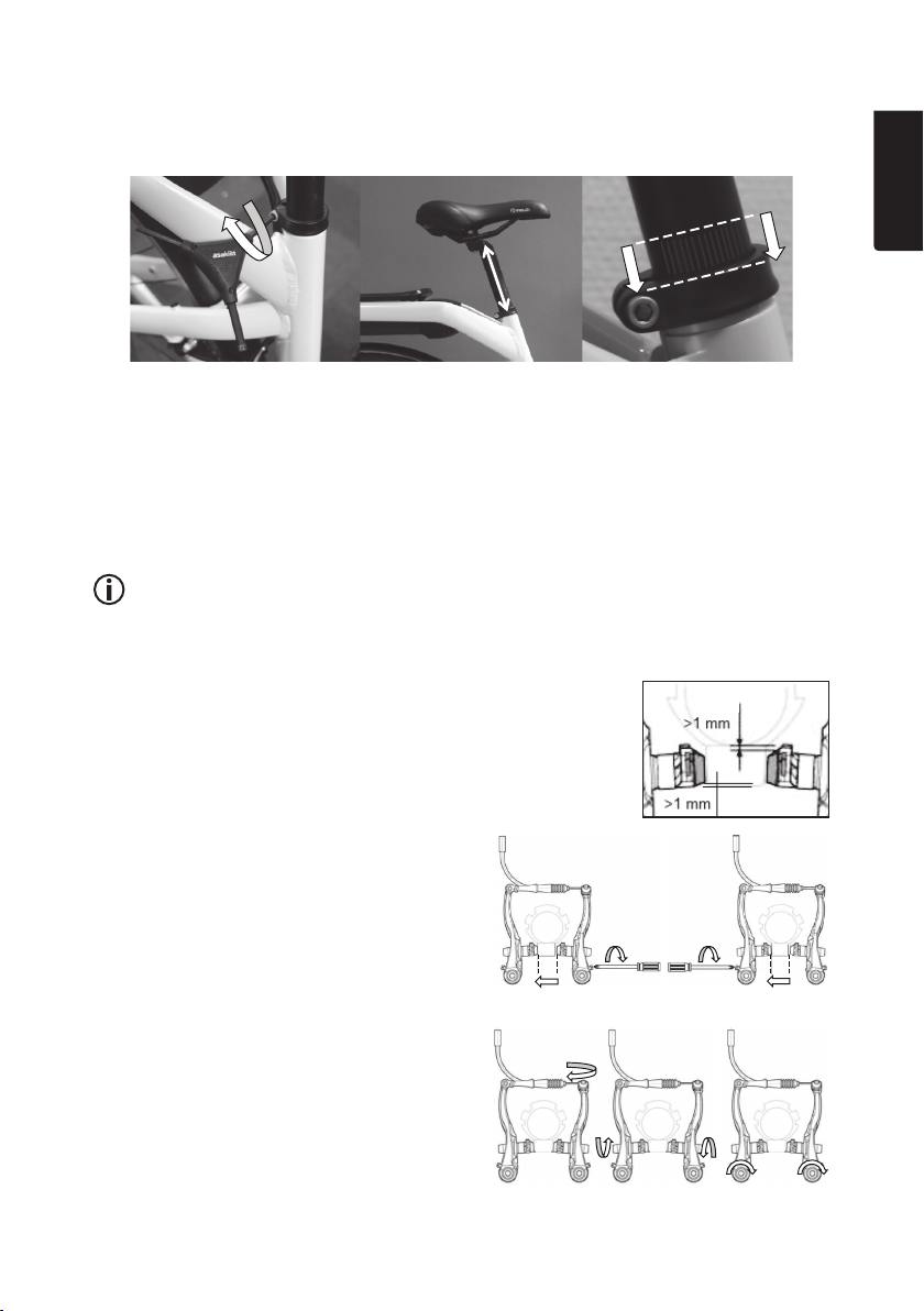
Rim brakes/hand brakes
Warning:
Sudden or excessive application of thefront brake could lock thefront wheel, causing therear
wheel to lift off theground and thecyclist to be thrown over thehandlebars.
• For bicycles sold in all countries except theUK:
- Brake lever (M), on theleft side of thehandlebars controls thefront brake whilst brake
lever (Q), on theright side of thehandlebars controls therear brake.
• For bicycles sold in theUK:
- Brake lever (M), on theleft side of thehandlebars controls therear brake whilst brake
lever (Q), on theright side of thehandlebars controls thefront brake.
Gently pull both brake levers at thesame time to brake smoothly.
• On surfaces with good traction, you can brake alittle more with thefront brake for alittle
better stopping power.
• On surfaces with poor traction, you should beware of applying thefront brake too hard and
instead control your speed with therear brake.
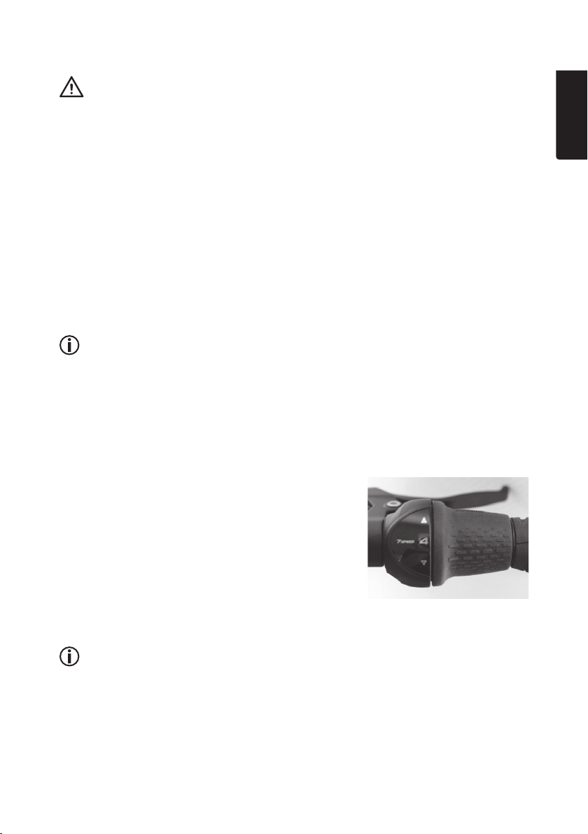
Changing gears
Information
• You can change gear regardless of whether you are pedalling or whether thebicycle is
stationary or moving.
• You can change one gear at atime or twist thegear shifter through several gears at once.
• Thecorrect gear to choose depends upon what physical condition you are in combined
with thecurrent level of resistance offered by environmental factors such as theterrain,
slope, ground surface, weather and wind conditions. As ageneral rule, alow gear should
be chosen when encountering ahigh cycling resistance; and ahigher gear for alower
resistance.
1. Twist thegear shifter backwards, towards [ + ],
to change to ahigher gear.
2. Twist thegear shifter forwards, towards [ - ],
to change to alower gear.
Using the cycle lights
Information
When cycling without assistance from themotor, theelectrical system must be switched on in
order for thelights to work.
1. Push and hold in [ - ] on thecontrol unit for about 3 seconds. Thelights will come on.
2. Hold thebutton in again to switch the lights off.

8
Svenska
Elcykel City – snabbguide
Art.nr 18-1487 Modell City
31-9781-1, 31-9781-2 City
Snabbguide
Viktigt!
• Snabbguiden ger dig information om hur du ska montera din elcykel.
• Snabbguiden ger dig grundläggande information om elcykelns funktioner.
• För din säkerhet och för att du ska kunna använda alla funktioner ska du läsa den
medföljande bruksanvisningen innan du använder elcykeln.
Bruksanvisning
Se den medföljande bruksanvisningen för utförlig information gällande:
• Säkerhet
• Inställningar och justeringar
• Användning
• Skötsel och underhåll
• Service och underhåll
• Garanti
• Kontaktuppgifter
Produktbeskrivning
Cykelkartongen innehåller följande delar:
• Elcykel
• Batteri
• Batteriladdare
• Styre/styrstam
• Pedaler (par)
• Bruksanvisning
• Snabbguide/monteringsanvisning
Förberedelser
1. Packa upp cykeln och alla delar ur kartongen.
2. Avlägsna allt emballage.
3. Kontrollera att alla delar finns med.
4. Plocka fram lämpliga verktyg för montering och grundläggande justering.
- Insexnyckel 5, 6 och 3 mm
- Blocknyckel eller hylsa 15 och 19 mm
- Pedal-/blocknyckel 15 mm
- Momentnyckel
- Cykelfett
- Cykelpump

9
Svenska
Ladda batteriet
1. Anslut batteriladdarens stickpropp till ettvägguttag och
laddkontakten till batteriet.
- Den röda lysdioden på batteriladdaren indikerar att
batteriet laddas.
- Den gröna lysdioden på batteriladdaren tänds när
batteriet är fulladdat. Det tar ca 6−8 tim att ladda upp
batteriet till full kapacitet.
2. Dra ut laddarens stickpropp ur vägguttaget och avlägsna
laddkontakten från batteriet.
Sätt i batteriet i batterifacket
1. Skjut in batteriet under
pakethållaren tills det
klickar fast ifästet.
Tryck ner handtaget.
2. Lås fast batteriet och
ta ur nyckeln.
Montering
Information
Cykelfett är inte nödvändigt men underlättar när du senare ska lossa på någon del, t.ex. höja eller
sänka styret.
Styre och styrstam
Varning!
• Om styrstammen monteras för högt istyrröret kan den lossna, med risk för person- och
materialskador.
• Markeringen för minsta inskjutning av styrstammen istyrröret får inte synas ovanför kanten
för den övre styrlagermuttern.

10
Svenska
1. Smörj in den nedersta delen av styrstammen,
skruven och dess mutter med etttunt lager
cykelfett.
2. Skruva insexskruven (6 mm) istyrstammens centrum
några varv moturs, skruva inte loss den helt.
3. För ner styrstammen igaffelröret, välj höjd på styret.
4. Vrid styrstammen med hjälp av styret så att den
sitter rakt.
Tips! Kontrollera att styret är vinkelrätt mot
framhjulet eller att styrstammens horisontella del
är riktad ilinje med framhjulet.
5. Dra/vrid täckkåpan uppåt
så att du kan försäkra dig
om att markeringen för min.
inskjuten längd försvinner
under kanten på den övre
styrlagermuttern.
6. Dra fast insexskruven
istyrstammens centrum.
7. Tryck täckkåpan på plats.
Pedaler
Viktigt!
• Vänster pedal är märkt Lpå pedalaxelns ände.
Den är vänstergängad, dvs. den ska skruvas fast
moturs. Passar endast på vänster vevarm.
• Höger pedal är märkt Rpå pedalaxelns ände.
Den är högergängad, dvs. den ska skruvas fast
medurs. Passar endast på höger vevarm.
1. Lägg på etttunt lager cykelfett på pedalaxelns
gängor.
2. Skruva fast pedalen ivevarmen för hand.
3. Dra åt pedalen (15 mm).
This manual suits for next models
2
Table of contents
Languages:
Other Asaklitt Bicycle manuals


