Asaklitt CITY User manual

Suomi Deutsch
Norsk
Svenska
English
Ver. 20180328
Art.no. Model
18-1487 CITY
31-9781-1, 31-9781-2 CITY
City Electric Bicycle
Elcykel City
Elsykkel City
City -sähköpyörä
Elektrofahrrad City


3
English
City Electric Bicycle
Art.no 18-1487 Model City
31-9781-1, 31-9781-2 City
Please read theentire instruction manual before use and then save it for future reference.
We reserve theright for any errors in text or images and any necessary changes made to technical data.
In theevent of technical problems or other queries, please contact our Customer Services (see address details on theback).
Safety
Symbol guide
Warning: Warning for apossible hazard which
could lead to serious personal injury and/or
damage to theproduct if thewritten instructions
are not followed.
Important: Warning for apossible hazard which
could lead to minor personal injury and/or damage
to theproduct if thewritten instructions are not
followed.
Note/Information.
General safety instructions
for bicycles
Warning:
• Thebicycle is designed to be ridden on normal roads
and not for terrain or competitive use. Any form of use
other than that described in this instruction manual
can lead to aserious risk for personal injury or material
damage.
• Never brake hard using thecoaster brake in slippery
conditions, e.g. on gravel, ice, snow or wet tarmac.
• It may become difficult to control thebicycle in wet or
windy weather conditions. Reduce your speed and
exercise greater caution, or use analternative form of
transport.
• Always brake using therear brakes first before
attempting to use thefront brakes. This especially
applies if road surfaces are slippery.
• For steep hills several braking methods should be
combined, otherwise using thecoaster brake may
cause therear wheel to overheat.
• As with all mechanical components, thebicycle
is subject to wear and high stress loads. Different
materials and components may react to wear or
stress fatigue in different ways. All components have
acertain lifespan and if thelife of acomponent has
been exceeded, it may suddenly fail causing possible
injury to theuser. Any forms of cracks, scratches or
changes of colouring in highly stressed areas indicate
that thelife of thecomponent has been reached and it
should be replaced.
• When brakes are applied, thebrake pads wear against
thewheel, which means that thewheel rims and brake
surfaces become worn over time. Therate of wear
and tear depends on several factors, e.g. theway in
which thebrakes are used, road conditions, how often
thebrake pads are replaced, and how often thebrake
pads and wheels are cleaned. Thesides of thewheel
rim can eventually become so thin that they collapse,
which can result in serious personal injury and material
damage. Check thewheels regularly, and replace
wheels that show signs of wear.
• Brakes and braking components can become very hot.
Do not touch them during, or shortly after, use.
• Anopen, unplugged end on thehandlebar could cause
injury in theevent of anaccident. Check that theends
of thehandlebars are covered by thehandgrips or with
handlebar plugs.
• There may be sharp points on theteeth of thecogs
and sprockets.
• Thepedals may have sharp edges and serrations.
• Moving parts can cause cutting and crushing injuries,
even resulting in thebreaking of bones.
• Clamps and other parts may cause crushing injuries.
• If you cycle in conditions with poor visibility (such as in
fog, twilight or at night), others many find it difficult to
see you, and therisk of anaccident increases. Always
use lights (front and rear) when cycling in poorly lit
conditions where visibility is low.
• You expose yourself to increased risk if you use thebicycle
in away that is not recommended, e.g. if you:
- Perform jumps with thebicycle.
- Cycle over tree roots and branches, stones, or
other similar objects.
- Cycle on challenging terrain.
- Cycle in anunusual manner.
• Anexcessive load can cause theframe or other parts
to break, thus increasing therisk of injury. Minimise
therisk of injury and damage by using thebicycle in
thecorrect manner.
Important:
• Tighten all nuts, bolts and screws, but do not overtighten.
Use atorque spanner to ensure thecorrect level of
torque (where such levels are stated).
• Adjust thebicycle so that it fits you and your body
type.
• Always conduct asafety check before using.
• Always use aproperly adjusted and fitted helmet.
• Always keep both hands on thehandlebars.
• Wear clothing that makes you visible to your fellow
road users.

4
English
• Thebicycle must be equipped with wheel reflectors
(both front and rear) and pedal reflectors. Make sure
that all reflectors are clean and visible.
• When riding in darkness, ensure that you have properly
functioning lights, both front and rear.
• Remember that rules and regulations for bicycles
will differ from country to country. This may include
regulations regarding front, rear and side reflectors,
along with front and rear lights. It is your responsibility
to familiarise yourself with therules and regulations that
apply in your country.
• Always ride in thesame direction as traffic flow.
Never ride against traffic.
• Always follow thelocal traffic regulations.
• Show consideration in traffic. Don’t ride close to
pedestrians, horse riders or thedisabled.
• Never use loose fitting clothing or similar apparel that
can get caught in thebicycle chain or wheels.
• Changes to thebicycle or its components can make it
unsafe to use. Each part and component of thebicycle
has been carefully chosen and tested. Thesafety
aspect of safety-critical components, accessories and
spare parts is not always obvious. Therefore, use only
original or compatible parts when making repairs or
when fitting accessories.
• Special tools and specialist knowledge make it easier
to assemble thebicycle and to make theinitial settings.
If you are at all unsure, this should be performed by
somebody with theappropriate competence.
• Incorrectly performed mechanical work can make
thebicycle unsafe to use. Something as simple as
tightening ascrew or bolt to theincorrect level of
torque may result in some part of thebicycle breaking,
causing you to lose control of thebicycle and have
anaccident.
• We recommend that all servicing, repairs and fitting
of accessories are performed by aperson with
therequisite competence and experience. Your safety
depends on thecorrect performance of maintenance.
• Any tampering or modification of theelectrical system,
frame, forks or other components can make thebicycle
dangerous to use.
• Acomponent that is not adapted for thebicycle, or
that has been incorrectly fitted, can subject thebicycle
to major stress with theresulting risk of personal injury
or material damage.
• Before you fit any accessories onto thebicycle, or
make changes to any part, it is your responsibility to
ensure that thechange you intend to make is both
compatible and safe.
• If you wish to use a child seat, make sure not to
exceed the max. weight allowed on the bike rack.
• Use a child seat that conforms to EN 14344.
• Adhere to the instructions that come with the child seat.
• Fitting achild seat will change thecentre of gravity of
thebicycle, which can make it difficult to manoeuvre.
• If a child seat is used, make sure that the maximum
total weight limit of the bicycle is not exceeded.
• If theposition of thesaddle has not been correctly
adjusted to suit you, or if thesaddle does not suit
your body type, you risk causing damage to your
nerves and blood vessels. Adjust theposition of
your saddle if you experience pain or discomfort.
Special safety instructions for
electric bicycles (EPAC)
Warning:
The charger is designed for indoor use only.
• Please follow the instructions on the label of thecharger.
• Never connect thepoles of thebattery or thebattery
charger using electrically conducting objects.
• Never expose thebattery or thebattery charger to
vibrations or bumps beyond that extent which occurs
during normal use.
• Thebattery may only be charged using thesupplied
charger.
• Thebattery and battery charger must never be
exposed to liquids or fire. Risk of explosion!
• When charging thebattery, do not touch either
thebattery or thebattery charger with damp hands.
• Neither thebattery nor thebattery charger may be
opened for any form of repair or modification.
• Never use adamaged battery.
• Never allow thebattery or thebattery charger to be
handled by children.
• During charging, thebattery charger must never be
covered.
• Never use thebattery charger if its cables have been
damaged.
• Never charge thebattery in temperatures below
0°C or above 40°C.
• Always remove thebattery from thebicycle when
performing any form of maintenance, service or
mechanical settings to thebicycle. Thesteering system
of theelectric bicycle must never be modified nor used
in any way other than that described in themanual.
Insurance
Your electric bicycle is to be insured in thesame way as
aregular bicycle. Contact your insurance company for
more information about insurance conditions.
Instruction manual
Important:
Please read theentire instruction manual before use and
then save it for future reference.
Theinstruction manual provides you with essential
knowledge about your electric bicycle, with regard to:
• safety
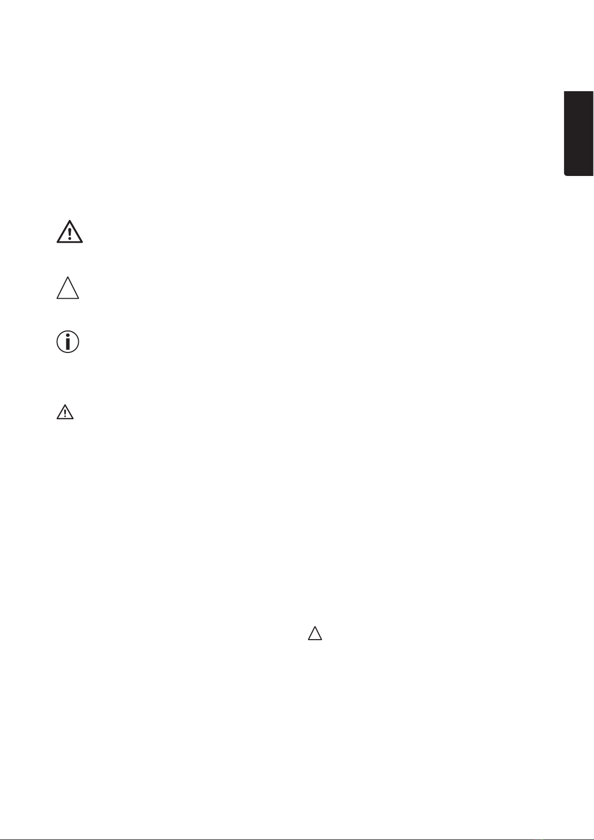
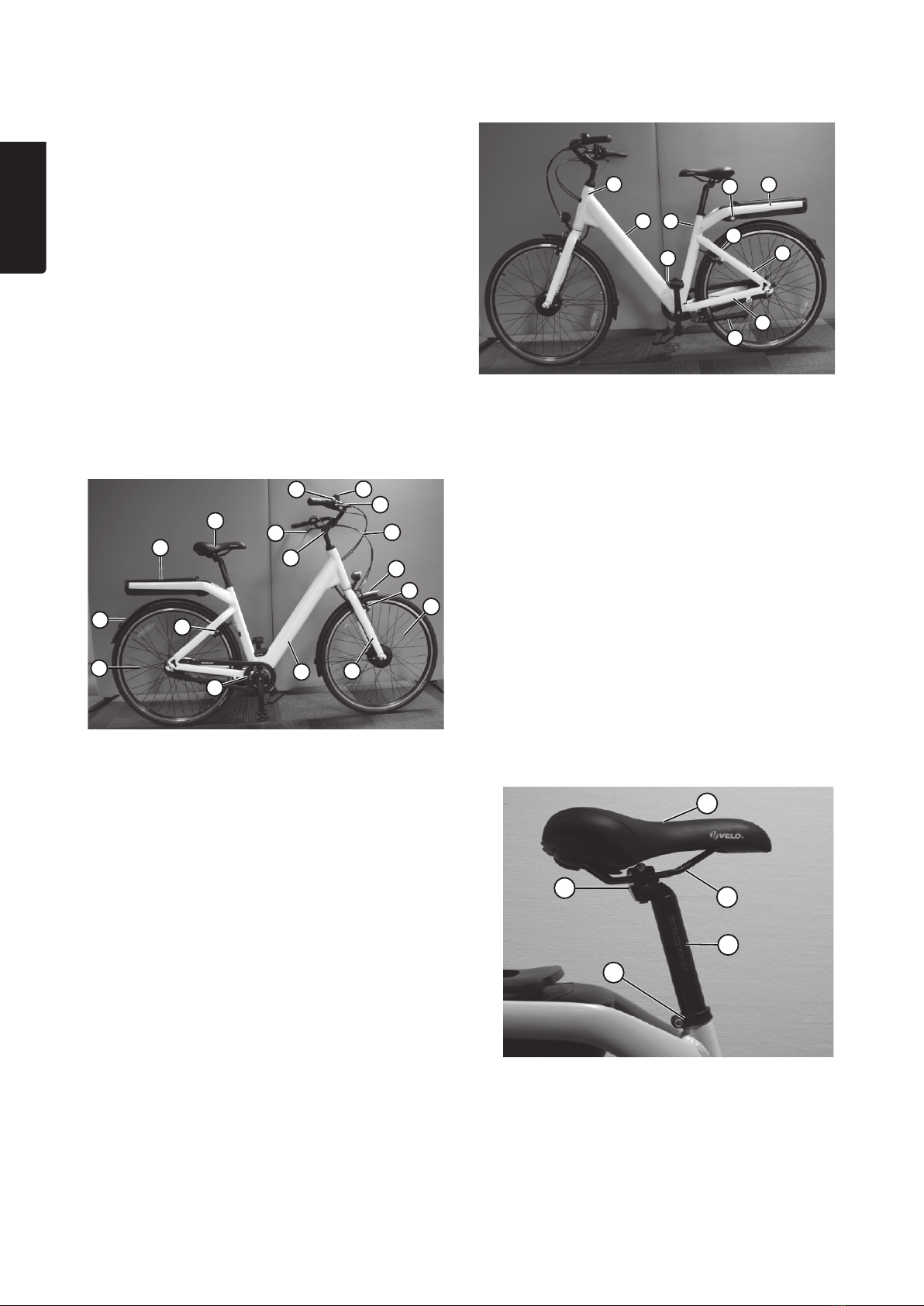
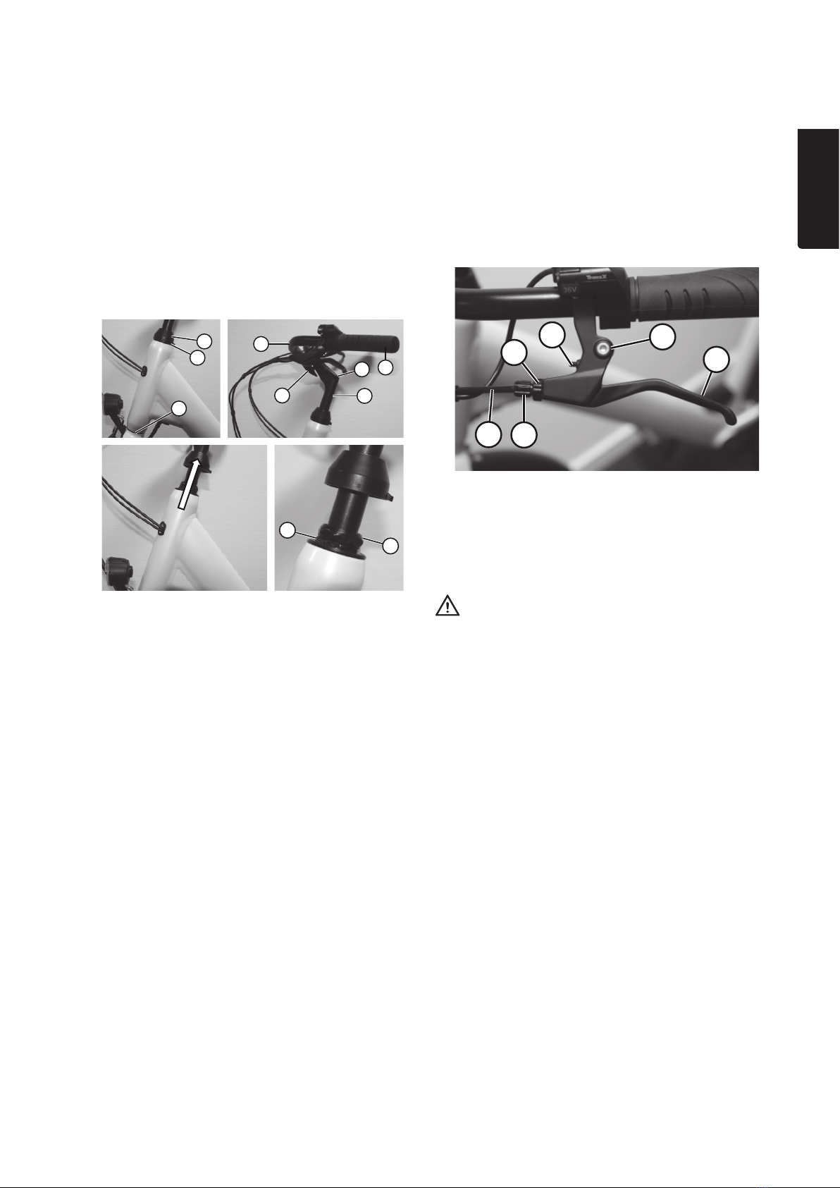
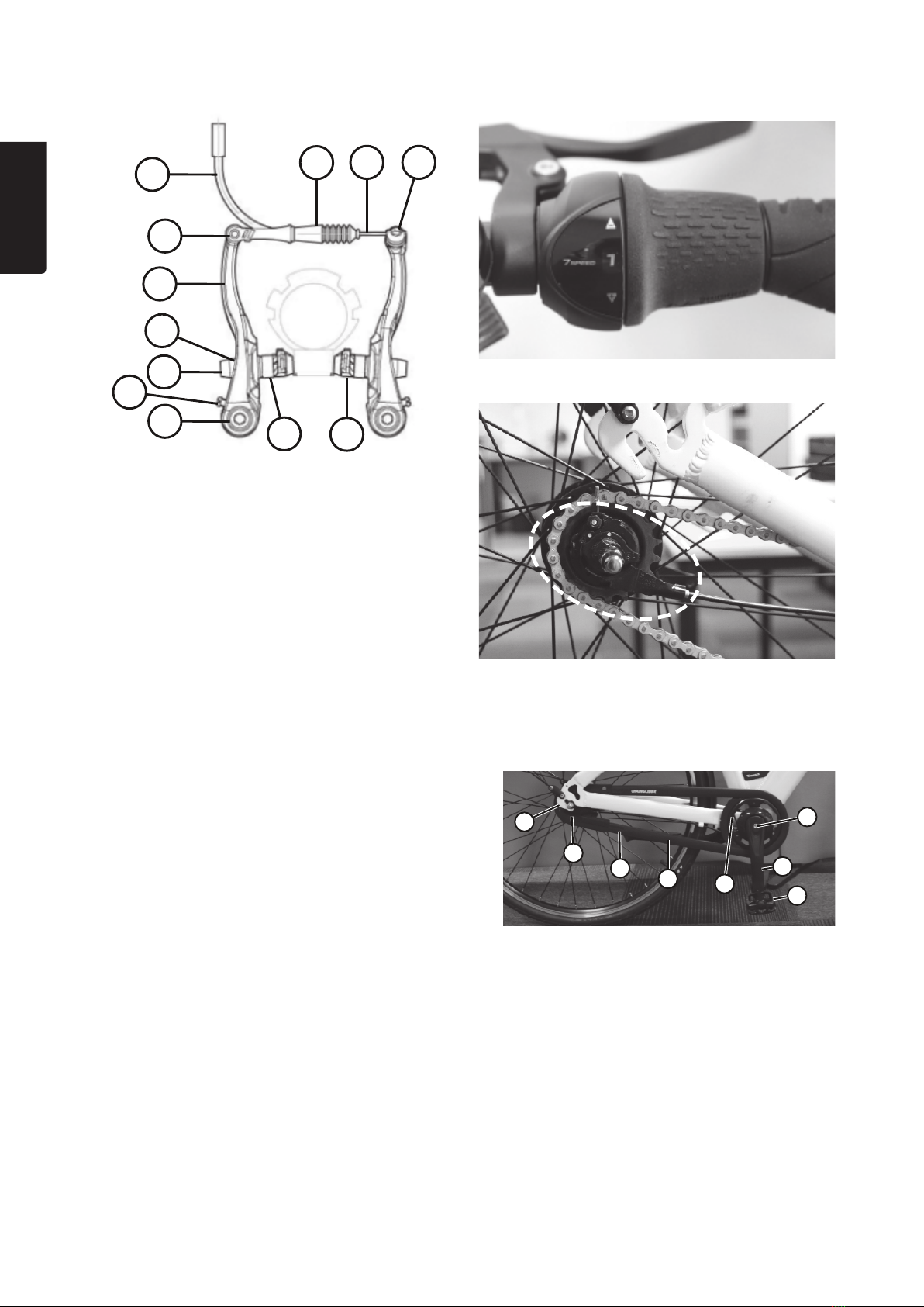
• functions and parts
• assembly
• settings and adjustments
• usage
• care and maintenance.

5
English
A2
A1 A3
A4
A1. Cover for charging contact
A2. [ ] Main power switch
A3. Battery charge status indicator
A4. Charging connector
Control unit/display (C)
• Thecontrol unit allows you to adjust your settings.
• Thedisplay shows your chosen settings, actual speed
and thebattery status.
C7
C1
C8
C6
C5
C4
C3
C2
C1. [ ] On/off
C2. [-] Decrease motorised assistance
C3. [+] Increase motorised assistance
C4. LED indicator for walking assistance
C5. Display showing speed as well as error codes
C6. Indication of battery capacity
- Green = 100 % charged
- Yellow = 50 % charged
- Red = fully discharged
C7. Micro-USB connector (for software updates)
C8. Indications for motorised assistance
- 0 bars = No assistance
- 1 bars = 25 % assistance
- 2 bars = 50 % assistance
- 3 bars = 75 % assistance
- 4 bars = 100 % assistance (= 25km/h)
Motor (F)
• Themotor is integrated into thefront wheel hub and
directly drives thefront wheel.
• Themotor offers four speed/assistance modes and
awalking mode, as well as fine-tuning of thetorque in
nine increments.
Pedalling sensor (H)
H
• Thepedalling sensor is mounted on theoutside of
theframe beneath thecrankset.
• When you cycle with motorised assistance activated,
asignal is sent from thesensor, which starts themotor.
A
B
C
D
E
F
G
H
Product description
- the functioning of
the electric bicycle
• Theelectric bicycle can be used as aregular bicycle,
entirely without motorised assistance.
• Theelectric bicycle offers motorised assistance in four
power modes/speeds when you are cycling, as well
as walking assistance to make it easier when you are
leading thebicycle.
• Motorised assistance can be used at speeds of up to
25km/h. At speeds exceeding 25km/h, themotor
turns itself off.
A. Battery
B. Rear light
C. Control unit/display
D. Mains lead
E. Front light
F. Motor
G. Speed sensor (inside motor/hub)
H. Pedalling sensor (behind chain sprocket)
Battery (A)
• Thebattery is located beneath thebike rack and can
easily be taken out and put back.
• Thebattery can be locked into place in thebattery
compartment.
• Therechargeable battery is of thetype li-ion, which means
that it can store agreat deal of energy for its size.
• Thebattery must be charged using thesupplied charger.

6
English
I
K
L
N
M
OP
Q
R
S
T
U
J
V
W
X
Y
I. Rear wheel
J. Rear mudguard
K. Bike rack
L. Saddle and seat post
M. Left brake lever
N. Steering
O. Gear shifter
P. Bicycle bell
Q. Right brake lever
R. Brake/gear cables
S. Front mudguard
T. Front rim brake
U. Front wheel
V. Front fork
W. Frame
X. Drivetrain
Y. Rear rim brake
Speed sensor (G)
• Thespeed sensor is integrated with themotor and
thefront wheel hub, and senses thespeed of thewheel.
• Theactual speed is shown on thedisplay when
theelectrical system is turned on.
Front light (E)
• Thelights are powered by thebattery, and can be used
regardless of whether thebicycle is stationary or when
you are cycling with or without motorised assistance.
• Theglass of thelight unit also functions as areflector.
Rear light (B)
• Thelights are powered by thebattery and can be used
regardless of whether thebicycle is stationary or when
you are cycling with or without motorised assistance.
• Theglass of thelight unit also functions as areflector.
Other parts of the bicycle
Frame (W)
W1
W3
W4
W5
W2
W6
W7
W8
W9
W10
W1. Head tube
W2. Down tube
W3. Scratch protection
W4. Seat tube
W5. Battery release button
W6. Bike rack stay
W7. Threaded fixing for installing alock (lock sold separately).
W8. Rear fork
W9. Chainstay
W10. Stand
Saddle and seat post (L)
• Theseat comprises asaddle and aseat post, which is
thepart of thecycle that bears thegreatest part of your
weight.
• Theseat post connects thesaddle to theframe and
allows you to adjust theheight of thesaddle.
• Theposition of thesaddle on theseat post can be
adjusted in all directions.
• Theposition of thesaddle is important to make theact
of cycling comfortable, safe and efficient.
L4
L5
L3
L2
L1
L1. Saddle seat area
L2. Saddle rails
L3. Seat post
L4. Seat post clamp
L5. Saddle clamp

7
English
Steering (N)
• Thesteering system consists of thehandlebars, stem
and headset.
• Thefunctioning of thesteering system is important to
make theact of cycling comfortable and safe.
• Theheadset hold thefront fork tube in place in
theframe and allow thefront wheel/steering column
to move freely from side to side. Thefriction within
theheadset bearings is adjusted with two bearing nuts.
• Thelower part of thesteering stem is screwed
into thetube of thefront fork, and its position both
determines theheight of thehandlebars and ensures
that they are fixed straight.
• Thehandlebars are screwed into place in thestem clamp.
N1
N2
N3 N4
N5
N6
N7
N8
N9
N10
N1. Lower bearing
N2. Upper bearing
N3. Top cap
N4. Handlebars
N5. Handgrip
N6. Stem centre screw
N7. Steering stem
N8. Handlebar-clamp screw
N9. Lower bearing nut
N10. Upper bearing nut
Braking system (M, Q, T and Y)
• Thebrakes are used to reduce thespeed of thebicycle
and to bring it to ahalt, which is of critical importance
for safety.
• To ensure maximum safety, your electric bicycle is fitted
with three braking systems.
- Foot/coaster brake on therear wheel
- Hand/rim brake on thefront wheel
- Hand/rim brake on therear wheel
Foot/coaster brake on the rear wheel
• Thefoot braking system applies abrake to therear wheel.
• Thebraking mechanism is located inside thehub of
therear wheel.
• Thebrake is activated by thechain when thepedals/
crank arms are pedalled backwards.
Hand/rim brake on the front wheel (T)
and rear wheel (Y)
• Thehand/rim braking system consists of afront brake
(T) and arear brake (Y).
• Thefront brake is mounted on thefront fork, and
therear brake is mounted on therear fork.
• Therim brake is activated by abrake cable when
thebrake lever is pressed towards thehandlebars.
Brake levers
M/
Q1
M/
Q5
M/
Q2
M/
Q4
M/
Q3 M/
Q6
M/Q1. Adjustment screw
M/Q2. Brake cable
M/Q3. Locking ring
M/Q4. Adjustment screw
M/Q5. Pivot point
M/Q6. Brake lever
Warning:
For bicycles sold in all countries (except theUnited
Kingdom), thefollowing applies:
• Thebrake lever (M) on theleft-hand side of
thehandlebars controls thefront brake (T), whilst
thebrake lever (Q) on theright-hand side of
thehandlebars (N4) controls therear brake (Y).
For bicycles sold in theUnited Kingdom, thefollowing
applies:
• Thebrake lever on theleft-hand side of
thehandlebars controls therear brake, whilst
thebrake lever on theright-hand side of
thehandlebars controls thefront brake.

8
English
T/Y1. Mounting screw/pivot point brake arm
T/Y2. Adjustment screw spring tension
T/Y3. Locking screw for brake pad
T/Y4. Spacer washer thin
T/Y5. Brake arm
T/Y6. Link/pivot point
T/Y7. Brake cable guide
T/Y8. Gaiter
T/Y9. Brake cable
T/Y10. Mounting screw for brake cable
T/Y11. Brake pad
T/Y12. Spacer washer thick
Gear system (O and X8)
• Thebicycle is fitted with 7 gears.
• Thegear mechanism (X8) is built into thehub of
therear wheel (I).
• Thegear shifter (O) is agrip shift, located on theright-
hand side of thehandlebar. Thegears are numbered
on theshifter from thelowest gear (1) to thehighest (7).
• Thegear shifter operates thegear mechanism by
means of agear cable (R), which is attached to agear
switch on theright-hand side of thehub.
T/Y4
T/Y3
T/Y1
T/Y2
T/Y6
T/Y5
T/Y7
T/Y8 T/Y9 T/Y
10
T/Y
12
T/Y
11
Gear shifter (O)Brakes
Note: Thewheel has been separated from therear fork,
and thechain guard has been disassembled, in order to
expose theouter gear mechanism)
Drivetrain (X)
X1
X2
X3
X4
X5
X6
X7
X8
X1. Crankshaft/crank bearings
X2. Crank arm
x3. Pedal
X4. Chain sprocket (behind chain guard)
X5. Chain (behind chain guard)
X6. Chain guard
X7. Sprocket (behind chain guard)
X8. Gear mechanism
Gear mechanism (X8)

9
English
Information
All settings and adjustments are described in theSettings
and adjustments section.
Frame, front
fork and critical
components
• Check that theframe, front
fork and any components that
are particularly subjected to
stress show no signs of cracks,
scratches, bumps, misshaping
or changes of colour, and do not
make any strange sounds.
Brakes • Make sure that thebrake levers are
securely fitted to thehandlebars.
• Check theposition of thebrake
pads and make sure they are
securely fitted.
• Test thebraking function of
thedifferent braking systems.
• Check that thehandbrake cables
are tightened and firmly fitted to
thebrake arms.
• Make sure that none of thecables
are pinched or damaged in any way.
Steering • Make sure that thehandlebars
are securely fitted and centred on
thestem.
• Check that thestem is securely
fitted and aligned with thefront
wheel.
Saddle and
seat post
• Check that thesaddle is aligned
with theframe.
• Check that thesaddle cannot be
twisted to theside or turned up/
down.
• Check that theseat post is
securely fitted in theframe tube.
Drivetrain • Check thelubrication of thechain.
Wheels • Check that thewheels are in line
and securely screwed into theends
of theforks.
• Wipe thewheel rims with adamp
cloth.
• Check thetyres for splits and cracks.
• Check theair pressure in thetyres.
• Check that thespokes are not
loose or damaged.
Battery • Make sure thebattery is fully charged.
• Make sure thebattery is locked
into place and that thekey has
been removed from thelock.
Reflectors
and lights
• Check that thereflectors are clean,
undamaged and firmly fixed.
• Check that thelights are clean and
fully functioning.
Assembling the bicycle
1. Unpack thebicycle and all parts from thebox, and
remove all packaging.
2. Charge thebattery and fix it into place in thebicycle’s
battery compartment (see Battery in theUsage section).
3. Install thestem and handlebars (see Steering in
theSettings and adjustments section).
4. Assemble thepedals (see Drivetrain in theSettings
and adjustments section).
5. Check that thebrake pads are fitted correctly
(see Hand/rim brakes in theSettings and
adjustments section).
6. Check that thebrake cables are tightly connected to
thebrake arms (see Hand/rim brakes in theSettings
and adjustments section).
7. Check that thewheel nuts are tight (see Wheels in
theSettings and adjustments section).
8. Inflate thetyres (see Wheels in theSettings and
adjustments section).
Preparing for your first
bike ride
Information
• Read theinstruction manual carefully and familiarise
yourself with thebike so you understand how it works
in all situations.
• All settings and adjustments are explained in
theSettings section.
• All instructions concerning how to use thebicycle can
be found in theUsage section.
• Adjust thebicycle to suit your body type. To achieve
thebest levels of safety, control, comfort and performance,
it is important that thebicycle is adjusted to suit you.
• Take ashort test ride every time you change any of
thesettings.
1. Adjust thesaddle (L) and thesteering (N).
2. Make sure you know how to safely mount and
dismount thebicycle.
3. Take ashort, low speed test ride on flat ground in anarea
free of traffic to familiarise yourself with thebicycle.
4. Place great importance on learning how to brake and steer.
5. Learn which brake lever operates thefront rim brake
and which operates therear rim brake.
6. Learn to change gear.
7. Learn to use themotorised assistance.
Checks to be performed
before every ride
Warning:
• If thebicycle does not function as intended, you could
lose control and risk personal injury and/or material
damage.
• Before use, always check thebicycle in accordance
with theinstructions in theinstruction manual.
• If any part of thebicycle is faulty or does not work
properly, you must ensure that it is adjusted/repaired
before continuing to use it.

10
English
Settings and adjustments
Warning:
Remember to take ashort test ride every time you change
any of thesettings.
Important:
• You should not attempt to change any settings
or make any adjustments that require specialist
knowledge or specialist tools.
• You will be able to change/make most of thesettings/
adjustments yourself, requiring only alimited range of
tools.
Suitable tools
• Hex (Allen) key 5, 6 and 3mm.
• Spanner (open-ended or ring) 15 and 19mm
• Pedal (or open-ended) spanner 15mm
• Torque wrench
• Screwdriver
• Tyre levers
• Bicycle pump
Tightening of screws and nuts
Important:
• It is important that screws and nuts are tightened
to thecorrect tension to prevent personal injury or
material damage.
• If ascrew or nut is to be tightened to aparticular
torque (Nm), this is specified in theinstructions.
Use atorque wrench in order to achieve thecorrect
tightening torque.
• If no torque is specified in theinstructions, thescrew
or nut must be tightened so that it is securely fixed. As
ageneral rule, thelarger thescrew/nut, themore force
should be used when tightening. Be careful, however,
to not overtighten.
Tightening torque
Component Details Tightening
torque
(Nm):
Wheels 19 mm front wheel nuts 33–35
15 mm rear wheel nuts 37–39
Pedals 15 mm pedal spindle 21–23
Rim brakes 5 mm socket head screw,
which secures thebrake
arm to thefork fixing
6–8
5 mm socket head screw,
which holds thebrake
pads in place
6–8
5 mm socket head screw,
which secures thebrake
cable to thebrake arm
6–8
Steering
stem
6 mm socket head screw,
which secures thesteering
stem to thehead tube
21–23
6 mm socket head screw,
which secures thehandle-
bar to thesteering stem
21–23
Seat post 6 mm socket head screw,
which secures thesaddle
to theseat post
21–23
5 mm socket head screw,
which secures theseat
post to theseat tube
8
Basic torque settings for
the electric motor
• In addition to thefour speed/assistance modes, it is also
possible to adjust thetorque of theelectric motor in nine
increments, from thelowest torque (1) to thehighest (9).
• Thehigher thetorque, themore efficiently thepower
is transferred from themotor, which means that
themotorised assistance feels stronger.
Important:
Ahigh level of torque can be particularly advantageous
when accelerating from low speed or when cycling uphill,
but it can be adisadvantage when cycling on slippery road
surfaces or if you prefer alower level of intervention from
themotorised assistance.

11
English
Saddle and seat post
Saddle height
1. Rotate thecrankset so that one pedal (X3) reaches its
lowest point.
2. Sit on thesaddle and place your heel on thelowest-
placed pedal.
Saddle position
Thelongitudinal position of thesaddle is determined by
thelength of your legs.
1. Rotate thecrankset so that both pedals are at
thesame height.
2. Sit comfortably on thesaddle and place your foot on
thefront pedal. Thejoint of your toe should be directly
above thespindle of thepedal.
4. Press down [ ] for
>3 seconds to exit
thesettings menu.
3. Thesaddle is at thecorrect height when your leg is
almost straight.
Note:
Personal deviations may apply. Select asaddle height that
you feel comfortable and safe with.
1. Loosen thesocket head screw (5mm) on theseat post
clamp (L4).
2. Twist and raise/
lower theseat post
(L3) until thesaddle
is at thedesired
height.
3. Twist thesaddle
until it is straight –
i.e. until it is aligned
with theframe.
4. Check that
themarking for
minimum insertion
of theseat post is
not visible above
theseat post
clamp.
5. Tighten thescrew.
3. Check that your kneecap is vertically aligned with
thepedal spindle/toe joint.
- If your kneecap is behind this vertical line,
you must move thesaddle forwards.
- If your kneecap is in front of this vertical line,
you must move thesaddle backwards.
Thepositioning of theangle of thesaddle is amatter of
personal preference and taste, but most find it best when
thetop edge of thesaddle is horizontal.
C8
2. Press down [ + ] (C3)
and [ ] (C1) for
>3 seconds. One red
light-emitting-diode will
flash in thelower-right
field (C8).
C5
3. Press [+] or [-] to
select thetorque,
from 1–9.
Theselected number
will then be shown
on thedisplay (C5).
1. Turn on theelectrical system either with thepower
switch on thecontrol unit or on thebattery (C1 or A2). Adjusting the saddle height

12
English
1. Turn thesaddle
clamp (L5) socket
head screw (6 mm)
anti-clockwise
3–4 turns.
2. Move thesaddle
forwards or
backwards.
4. Tighten thesaddle clamp screw.
Handlebars, stem and headset
Height of the handlebars
Warning:
• If thestem is fixed too high up in thehead tube,
it can come away, causing risk for personal injury
and material damage.
• Themarking for theminimum insertion of thestem into
thehead tube must not be visible above theedge of
theupper bearing nut.
Adjusting the saddle position
1. Loosen the6mm
socket head
screw (N6) in
thecentre of
thestem (N7)
by turning it two
or three turns in
ananti-clockwise
direction.
2. Raise or lower thestem in thefork tube.
Note: If you are not able to move thestem, despite
twisting it, you can tap thescrew with apiece of wood
or plastic.
3. Twist thestem using thehandlebars (N4) so that it is
straight.
Handy tip: Check that either thehandlebars are
perpendicular to thefront wheel or thehorizontal part
of thestem is aligned in parallel with thefront wheel.
4. Pull/twist thetop cap upwards so that you can
check that themarking for minimum insertion length
disappears below theedge of theupper bearing nut.
5. Tighten thescrew.
6. Press thetop cap into place.
Angling and centring the handlebars
1. Loosen thesocket
head screw (6mm) of
thehandlebar clamp
(N8).
2. Twist thehandlebars
upwards/downwards
until you achieve
thedesired angle.
3. Check that thestem
is centred on
thehandlebars.
4. Tighten thescrew.
Headset
Important:
Adjustment of theheadset requires specialist knowledge
and tools.
Checking the headset
1. Hold thedown tube (W2) with one hand, and lift thebicycle
so that thefront wheel (U) leaves theground.
2. Turn thehandlebars from side to side with your other hand.
- If this movement feels heavy and you experience
obvious resistance, theheadset bearings (N1 and
N2) are either faulty or have been overtightened,
which must be corrected.
- If theside-to-side movement is easy and does not
involve any resistance, return thefront wheel to
theground and proceed to step 3.
3. Angle thesaddle
upwards or
downwards until
you achieve
thecorrect angle.

13
English
4. Move thebicycle forwards/backwards in short jerking
movements, and feel and listen to check there is no
free movement.
5. If you notice any free movement, this must be
corrected.
6. If you cannot detect any free movement, theheadset
bearings are correctly tightened.
Wheels
Removing the front wheel from
the front fork
1. Turn theadjustment
screw (M/Q1) and
thelocking ring (M/Q3)
on thefront brake
lever (M/Q) in aclock-
wise direction so that
thebrake pads (T11)
come as far away
from thewheel rims
as possible.
2. Pull thegaiter (T8) away from thecable guide (T7).
1. Loosen thewheel
nuts. Place
theinner washers
against thehub,
and theouter
washers against
thewheel nuts.
2. Rotate thewheel/
hub so that
theelectric cable
3. With your hand, press thebrake arms (T5) in against
thewheel and unhook thecable guide from thelink
(T6). Release thebrake arms.
4. Loosen thescrew for theholder on themudguard stay.
Remove thestay and theclamp for theelectric cable.
5. Separate theelectrical connectors.
6. Loosen both wheel nuts (19 mm) and remove
thewheel from thefront fork (V).
Fixing the front wheel to the front fork
Important:
• Thewheel axle must easily fit into thedropout slots in
theends of thefront fork. Note that thehub only fits
into theends of thefork when theflats on theaxle are
aligned with thestraight edges of thedropout slots.
• Ensure that theelectric cable comes out beneath
thewheel axle.
3. Cup one hand
around theprotective
cap of thebearing
and theupper part
of thehead tube
(W1). With your free
hand, pull thebrake
lever for thefront rim
brake so that it locks
completely.
from thewheel hub comes out beneath thewheel axle
and theflats of theaxle vertical.
3. Align theends of thefront fork with thewheel axle,
between thewashers, and push into place. Make sure
that thewheel axle slides all theway into thedropout
slots in theends of theforks.
4. Check that thewheel sits centrally between theforks,
and tighten thewheel nuts to 33–35 Nm.

14
English
5. Align themarkings of theelectrical connectors with
each other and press them together. Note: Press hard
until they click into place.
6. Ensure that thecable clamp grips around
thereinforced part of thecable, and screw together
thecable holder and themudguard stay.
Removing the rear wheel from the frame
1. Turn thegear shifter (O)
to position 1.
2. Turn theadjustment
screw (M/Q1) and
thelocking ring (M/Q3)
on therear brake
levers (M/Q) in
aclockwise direction
so that thebrake
pads (Y11) come
as far away from
thewheel rims as
possible.
7. Press thebrake arms
in against thewheel
rim, hook thecable
guide onto thelink,
and press thegaiter
into place.
8. Try applying thebrakes
and check that
thebrakes work (see
Brakes in theSettings
and adjustments
section).
3. Pull thegaiter (Y8) away from thecable guide (Y7).
4. With your hand, press thebrake arms (Y5) in against
thewheel and unhook thecable guide from thelink
(Y6). Release thebrake arms.
5. Remove thechain guard (X6) (see Drivetrain in
theSettings and adjustments section).
6. Loosen thesocket head
screw (5 mm) and thenut
(10 mm) that holds thebrake
stay in place on theleft-
hand chainstay (W9).
7. Loosen both wheel
nuts (15mm).
8. Push thewheel downwards/
forwards so that thewheel
axle comes away from
therear fork (W8).
9. Turn thelocking ring for thegear switch clockwise
until theyellow markings are aligned, then remove
thelocking ring.
10. Remove thelocking
ring and thegear
switch.

15
English
Fixing the rear wheel to the frame
1. Turn thegear shifter to position 1.
2. Position thewheel towards thefork ends with
thebrake stay pointing forwards.
11. Lift thechain (X5)
away from therear
sprocket (X7).
12. Remove thewheel.
3. Hook thechain
onto theteeth of
thesprocket, and
ensure that thechain
runs around thechain
sprocket (X4) at thefront.
4. Set thegear switch against theyellow markings on
thewheel axle.
5. Set theyellow dot on thelocking ring against theleft-
hand yellow dot on thegear switch. Turn thelocking
ring clockwise as far as it will go.
Important:
Theposition of thegear switch on thewheel axle is
very precise, so theslightest movement between
theyellow markings will prevent thecorrect positioning
of thegear switch. It will normally be very easy for
thelocking ring to be put into place. If it is not, this
indicates that theposition of thegear switch needs to
be corrected.
6. Set theends of therear
fork against thewheel
axle, and ensure that
thewashers inside
thewheel nuts are on
theoutside of thedro-
pout slots in theends
of thefork.
7. Pull thewheel back-
wards so that theaxle
slides part of theway
up thedropout slots
in theends of thefork.
Make sure that thetabs
on thesafety wash-
ers are inserted into
thedropout slots.
9. Adjust thetension of thechain (see Drivetrain in
theSettings and adjustments section).
10. Tighten both wheel nuts securely.
11. Tighten thescrew and nut on thebrake stay.
8. Centre thewheel bet-
ween thechainstays,
and lightly tighten
thewheel nuts.
13. Try applying thebrakes and check that thebrakes
work (see Brakes in theSettings and adjustments sec-
tion).
Hub/wheel bearings
Important:
Adjustment of thewheel bearings requires specialist
knowledge and tools.
1. Lift thebicycle so that thewheel leaves theground.
2. Take hold of thetyre/wheel and push it sideways in
short jerking movements.
3. Look, feel and listen to detect any looseness in
thewheel hub.
4. Spin thewheel and listen out for any unusual noise,
such as scraping or creaking.
5. Repeat this action with thesecond wheel.
If there is any looseness or creaking in thehub, this must
be corrected.
12. Press thebrake
arms in against
thewheel rim,
hook thecable
guide onto
thelink, and
press thegaiter
into place.

16
English
4. Use anadditional one
or two tyre levers at
intervals of 10–15cm,
and continue until
theentire side of
thetyre comes away
from thewheel rim.
2. Squeeze both sides of
thetyre together where
it meets thewheel
rim, and continue
around theentire
circumference of
thewheel.
3. At thepoint opposite thevalve, insert atyre lever
beneath theedge of thetyre. Prise up theedge of
thetyre and fix thetyre lever to one of thespokes.
5. Remove thevalve from
thehole in therim and
remove theinner tube
from thetyre.
6. Remove thetyre from thewheel rim.
Retting the tyre and inner tube
1. Loop one side of thetyre back onto thewheel rim.
2. Partially inflate theinner tube just so that thetube
resumes its shape.
3. At thevalve hole in
thewheel rim, pull up
theside of thetyre and
insert thevalve into
thehole.
4. Push theinner
tube inside thetyre
around theentire
circumference.
5. Hold thevalve in
place and push
theside of thetyre
around thevalve over
thewheel rim.
6. Run your hands
in opposite
directions around
thecircumference
of thetyre, pushing
theedge of thetyre
over thewheel rim as
you go.
Removing the tyre and inner tube
Remove thewheel from theframe or front fork
(see Wheels in theSettings and adjustments section).
1. Unscrew thevalve cap and fully deflate theinner tube.
7. If you are removing thetyre and inner tube because of
apuncture, you should:
- inspect both thetyre and therim for damage.
Check for damage both visually and by running
your hand along theinside of thetyre and wheel
rim. Check therim tape.
- Remove any glass, sharp objects, etc. and replace
thetyre when necessary.
Important:
Take care not to pinch theinner tube between theedge
of thetyre and therim.
7. Inflate thetyre, and then let theair out again.
8. Squeeze both sides of thetyre together where it
meets thewheel rim, and continue around theentire
circumference of thewheel.
Note
Steps 7 and 8 are important in order to prevent
theinner tube from being pinched between therim and
theedge of thetyre.
9. Inflate thetyre to therecommended pressure, which is
stated on theside of thetyre. For thebicycle’s original
tyres, thepressure is 3.5–6.0bar (50–85PSI).

17
English
Foot/coaster brake
For thefoot brake to function properly, it is important that
thechain has thecorrect tension. Therefore, regularly check
thetension of thechain (see Drivetrain in theSettings and
adjustments section).
Hand/rim brake
Warning:
Thefunctioning of therim brakes is critical for safety – pay
extra attention to reading and understanding theinstructions.
Brake levers
Theposition of thebrake levers on thehandlebars can
be adjusted. It is also possible to adjust thedistance of
theactual brake lever from thehandlebars/handgrip to suit
thesize of your hands. Small hands will require ashorter
distance.
Brakes
The position of the brake pads
M/
Q4
1. Loosen themounting
screw of thebrake
lever by turning it
afew times in ananti-
clockwise direction.
2. Move thelevers
inwards or outwards
along thehandlebars,
and/or move thelevers
to therequired angle.
3. When thebrake lever is in therequired position, tighten
thefixing screw.
4. Turn thesocket head screw (M/Q4):
- in aclockwise direction to reduce thedistance
between thebrake lever and thehandlebars.
- in ananti-clockwise direction to increase
thedistance to thehandlebars (thebicycle is
first delivered with this screw unscrewed to
themaximum amount, and with thegreatest
possible distance between thelever and
thehandlebars).
5. Check thedistance between thebrake pads and
therim, as well as thedistance between thebrake
lever and thehandlebars (see Brakes/Tension of
thebrake cable in theSettings and adjustments
section).
• Thebraking surface
of thebrake pads
must be parallel to
thewheel rim. There
should be adistance
of at least 1mm
between thetop
edge of thebrake
pad and thetyre,
and at least 1mm
between thebottom
edge of thebrake
pad and thebottom
edge of therim.
• If any of thebrake pads is not positioned as described,
this must be adjusted. For best results, adjust
thebrake pads in pairs.
1. Loosen thebrake pad set
screws (T/Y3) by turning
once or twice in ananti-
clockwise direction with
a5mm hex key. It will now
be possible to realign and
to move thebrake pads
upwards/downwards.
2. Lightly press thebrake pads
against thewheel rims by
squeezing thebrake lever.
3. Move thebrake pads into thecorrect position while
maintaining light pressure with thebrake lever.
4. Pull thebrake lever with full force and tighten thebrake
pad set screws.
5. Release thebrake lever and hold thebrake pads in
place, one by one, with your hand. Tighten thescrews
for thebrake pads.
Tension of the brake cable
Thedistance between
thebrake pads and
therim must be 1–2mm.
If thedistance is:
• greater than 2mm,
you must tighten
thebrake cable
• less than 1 mm,
you must loosen
thebrake cable.

18
English
For minor adjustments, you can turn thebrake lever
adjustment screw (M/Q1) for cable tension.
1. Turn thelocking ring (M/Q3) against theadjustment screw.
- Turn theadjustment screw (together with
thelocking ring) outwards/anti-clockwise to
increase thecable tension. Thedistance between
thebrake pads and wheel rims becomes smaller.
Thebrake lever moves away from thehandlebars.
- Turn theadjustment screw inwards/clockwise to
decrease thecable tension. Thedistance between
thebrake pads and wheel rims becomes greater.
Thebrake lever moves closer to thehandlebars.
2. Finally, tighten thelocking ring against thebrake lever
in order to fix theposition of theadjustment screw.
2. If thebrake arms move
unevenly, or if thebrake
pads are at unequal
distances from therim,
turn theadjusting
screw (in ananti-
clockwise direction)
on thebrake arm that
either moves themost
or whose brake pad is
furthest from therim.
M/
Q1
M/
Q3
If greater adjustments are required (which cannot be
achieved using theadjustment screw), you must adjust
theposition of thebrake cable (T/Y9) on thebrake arm.
T/Y
10
50-65 mm
T/Y2T/Y2
3. Hold theend of
thecable while you
loosen thesocket
head screw (T/Y10)
(5mm).
4. Pull thecable out from
thebrake arm to tighten
thecable, or push in
theopposite direction
to loosen thecable.
Thedistance between
theattachment point of
thecable to thebrake
arm and thelink on
theother brake arm must
be 50–65mm.
5. Tighten thescrew.
6. Finely-tune this adjustment as necessary, in
accordance with step1.
• Thetension of
thespring is adjusted
using ascrew next to
thebrake arm pivot
point (T/Y2).
1. Test thebrakes repeatedly while observing both
themovement of thebrake arms and thedistance
between thebrake pads and therims. Test whether it
requires much or little force to pull thebrake lever.
3. If adjusting thescrew in
accordance with step2
does not result in any
change, you should turn
theadjusting screw (in
aclockwise direction)
on thebrake arm that
moves theleast or whose
brake pad is closest to
therim. Test thebrakes
repeatedly while turning
thescrew in order to
see thedirect results of
theadjustment.
The brake arm spring tension
• Thebrake arms are spring-loaded, which means that
they are pressed outwards away from therim when
thebrake lever is not pulled.
• Thetension of thespring-loading must be thesame
for both brake arms in order to ensure that thebraking
force and thedistance between thebrake pads and
therims is equal on both sides.
• Thebraking system works most effectively when
theforce of thebrake arms’ spring-loading is as low as
possible while also being fully adequate for thebrake
arms to spring outwards, without obstruction, when
you release thebrake lever.
4. If thebrake arms move evenly but you think that
thebrake lever is stiff and hard to pull, try turning
theadjustment screws on both brake arms in ananti-
clockwise direction.
Note
• Adjust thescrews evenly on both sides until theresistance
of thebrake lever decreases.
• Make sure that you do not loosen thescrews so much
that they fall off. If you reduce thetension too much,
thebrake arms will not spring outwards. If this happens,
turn theadjustment screws in aclockwise direction.

19
English
2. Lightly bend out
therear part of
thesprocket protector
and pull it straight
backwards.
3. Free thefront part of thesprocket protector, pull it
forwards and remove it.
4. Prise up theconnection
between theouter
and inner guard –
begin with theupper
one from behind and
continue with thelower
one. Separate theouter
and inner guard at
thecrankset.
5. Lift away first theouter guard and then theinner guard.
6. Refit thechain
guard by
reversing this
process. Ensure
that all joins and
catches click into
place.
Chain tension
Important:
In order to function effectively, thechain must have
acertain tension/length. With use and wear, thechain
begins to stretch, so thetension of thechain must be
checked regularly.
1. Remove thechain guard (see Chain guard in
theSettings and adjustments section).
2. Place aruler on theground and lean it against
thecentre of thechain, between thefront sprocket and
thecrankset. Pull thechain upwards and measure how
much thechain moves vertically.
- If thedistance is greater than 12mm, thechain
tension must be increased.
- If thedistance is less than 6 mm, thechain tension
must be decreased.
3. Loosen thesocket
head screw (5 mm)
and thenut (10 mm)
which holds thebrake
stay in place on
theframe.
4. Loosen theright wheel
nut (15 mm).
• Thebicycle is fitted with afull-coverage chain guard,
which not only protects clothing from contact with
thechain but also protects thechain, cogs and
sprockets from dirt and moisture.
• Certain settings and repairs and servicing will require
theremoval of thechain guard.
1. Pull thered plug
straight out.
Drivetrain
Chain guard

20
English
5. Press thefront part of thewheel sideways against
- theright-hand chainstay to increase thechain tension
- theleft-hand chainstay to decrease thechain tension.
Feel thetension of thechain while you are pressing
thewheel.
6. Hold thewheel in place when thechain tension looks
right, and tighten theright wheel nut.
7. Loosen theleft wheel nut (15 mm).
8. Press thefront part of thewheel sideways in
thedirection needed to ensure that thedistance
between theside of therim/tyre and thechainstay is
equal on both sides of thewheel.
9. Tighten theleft wheel nut.
10. Check thechain tension in accordance with step3.
11. If required, repeat steps2–10 until thechain has
thecorrect vertical alignment and thewheel sits
centred between thechainstays.
12. Tighten both wheel nuts securely.
13. Tighten thescrew and nut on thebrake stay.
Pedals
Attaching the pedals
Important:
• Theleft pedal is marked L on theend of thepedal
spindle. It has aleft-hand thread, which means that it is
tightened by screwing it in ananti-clockwise direction.
This can only be used on theleft-hand crank arm.
• Theright pedal is marked R on theend of thepedal
spindle. It has aright-hand thread, which means that it
is tightened by screwing it in aclockwise direction. This
can only be used on theright-hand crank arm.
1. Apply athin layer of bicycle grease to thethreads on
theend of thepedal spindle.
2. Screw thepedal to thecrank arm by hand.
3. Tighten thepedal using apedal (or open-ended)
spanner (15mm).
Removing the pedals
1. Unscrew thepedal from thecrank arm using apedal
(or open-ended) spanner (15mm).
Important:
• Theleft pedal is unscrewed in aclockwise direction,
whilst theright pedal is unscrewed in ananti-clockwise
direction.
• Wear protective gloves.
Check for any looseness in the pedals
1. Take firm hold of thepedal and jerk it in all directions.
See if it feels loose.
2. If there is any looseness, first check that thepedal is
tightly screwed into thecrank arm.
3. If it still feels loose, thelooseness will be in thepedal
spindle, so you should replace thepedal.
Gears
Adjusting the gears
1. Turn thegear shifter to
position 4.
2. Check theposition of thetwo yellow markings on
thegear switch on theright-hand side of therear wheel
hub. Theposition of theouter marking is fixed, whilst
theposition of theinner marking varies according to
thetension of thegear cables.
- If themarkings are
aligned with each
other, thegears
have been correctly
adjusted.
- If theinner marking is in front of theouter marking,
you must turn thegear shifter adjustment screw
in ananti-clockwise direction until theyellow
markings are aligned.
- If theinner marking is behind theouter marking,
you must turn thegear shifter adjustment screw in
aclockwise direction until theyellow markings are
aligned.
3. Twist thegear shifter back and forth several times,
alternating between thehighest and lowest gear
positions. Turn thegear shifter to position 4.
4. Check that themarkings are aligned – fine-tune using
thegear shifter adjustment screw.
This manual suits for next models
3
Table of contents
Languages:
Other Asaklitt Bicycle manuals