Installation, Operation and Maintenance Manual IO-70100 RevG 12-178
Edition, marked on this product, the wire size listed for each product must be utilized to connect the unit
to your facilities’ power grid. Connections made with conductors other than the wire size listed may result
in dierent VPR’s.
Circuit Ampacity Limitations
Representative samples of these products have been investigated by Underwriters Laboratories,
Incorporated to withstand, without exposing live circuits or components at system voltages and fault
currents up to 200,000 AIC, as described in the Standard for Safety, Surge Protective Devices (SPD’s),
Standard 1449, Fourth Edition.
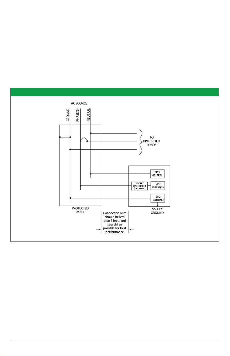
System Grounding and Bonding
The performance and safety of any SPD system is dependent on proper grounding and bonding.
Grounding is required for safety. Correct implementation also enhances equipment performance.
Incorrect grounding can reduce or impede the SPD’s operation. All electrical circuits to the SPD must
include an equipment- grounding conductor as required by the NEC and local codes.
An insulated grounding conductor is required in addition to any metallic raceway, which may be used as
a grounding conductor. For parallel-connected SPDs, the grounding conductor should be the same wire
size as the associated power conductors.
UNGROUNDED POWER SYSTEMS ARE INHERENTLY UNSTABLE AND
CAN PRODUCE EXCESSIVELY HIGH LINE-TO- GROUND VOLTAGES
DURING CERTAIN FAULT CONDITIONS. DURING THESE FAULT CONDITIONS ANY ELECTRICAL
EQUIPMENT, INCLUDING AN SPD, MAY BE SUBJECTED TO VOLTAGES WHICH EXCEED THEIR
DESIGNED RATINGS. THIS INFORMATION IS BEING PROVIDED TO THE USER SO THAT AN
INFORMED DECISION CAN BE MADE BEFORE INSTALLING ANY ELECTRICAL EQUIPMENT ON AN
UNGROUNDED POWER SYSTEM. CONTACT FACTORY FOR UNGROUNDED APPLICATIONS.
ATTENTION – LES SYSTÈMES D’ALIMENTATION NON-MISES À LA TERRE SONT INTRINSÈQUEMENT
INSTABLES ET PEUVENT PRODUIRE DES TENSIONS DE PHASE TRÈS ÉLEVÉES AU COURS DE
CERTAINES CONDITIONS DE DÉFAUT. PENDANT CES CONDITIONS DE DÉFAUT TOUT ÉQUIPEMENT
ÉLECTRIQUE, Y COMPRIS UN SPD (PROTECTEUR DE SURTENSION), PEUT ETRE SOUMIS A DES
TENSIONS SUPERIEURES À LEURS VALEURS STANDARDS. CETTE INFORMATION EST FOURNIE
À L’UTILISATEUR AFIN QU’UNE DÉCISION CORRECTE PEUT ÊTRE PRISE AVANT D’INSTALLER UN
ÉQUIPEMENT ÉLECTRIQUE SUPPLIMENTAIRE SUR UN SYSTÈME D’ALIMENTATION NON-MISE À LA
TERRE. CONTACTER L’USINE POUR LES APPLICATIONS NON-MISES À LA TERRE.
Grounding conductors must be routed with the associated power conductors in the same raceway
(conduit). When metallic raceways are used, adequate electrical continuity must be maintained at all
raceway connections, particularly raceway terminations to the electrical enclosures.
The use of isolating bushings or other means to interrupt a metallic conduit run is a potential safety
hazard and is not recommended.
Grounding Electrode
Surge protective devices do not discharge all surges to ground (earth). Surge protective devices can also
divert the surge current back to its source to complete the electrical circuit.
In the case of lightning whose potential is developed with respect to the earth, the SPD diverts the
surge current to the grounding electrode (earth connection). However, for most transient surges that
are developed by switching loads, the SPD diverts the surge current back to its source without involving
the grounding electrode.