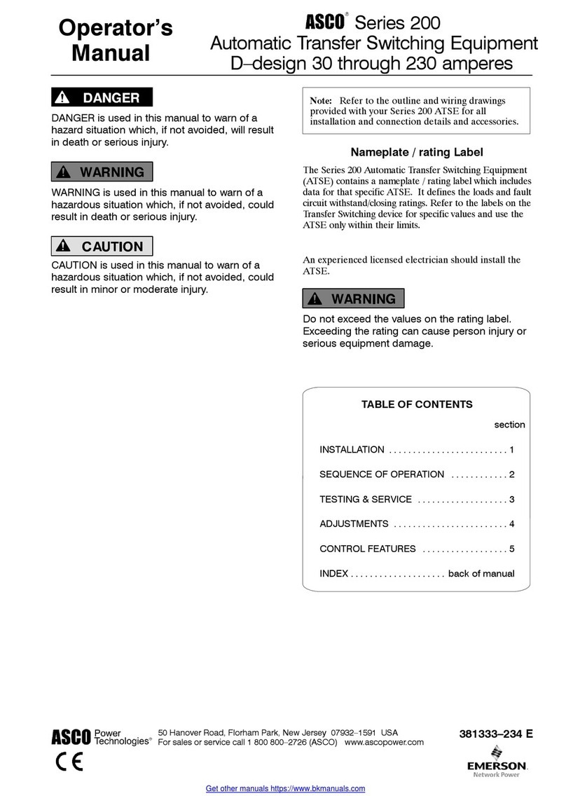
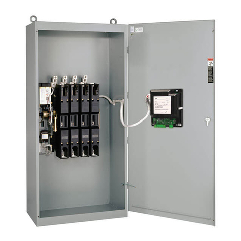
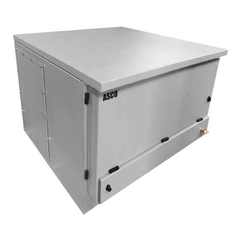
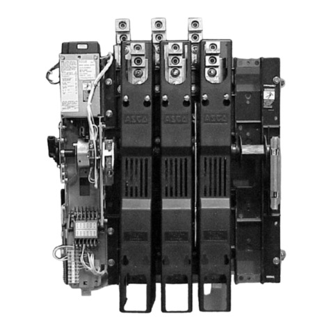
Asco 230 Series User manual

SERIES 230 Automatic Transfer Switch
C1000 Intelligent Controller User Manual
Document Version V1.3
Archive Date September 26, 2012
BOM Co e 31012665
Emerson Network Power provi es customers with technical support. Users may contact the nearest
Emerson Network Power sales office or service center.
Copyright © 2012 by Emerson Network Power Co., Lt .
All rights reserve . The contents in this ocument are subject to change without any prior notice.
Emerson Network Power Co., Lt .
A ress: No.1 Kefa R ., Science & In ustry Park, Nanshan District 518057, Shenzhen China
Website: www.emersonnetworkpower.com
Customer Service Hotline: 4008-876-510
E-mail: [email protected]


Contents
Chapter 1 Overview ............................................................................................................................................................ 1
1.1 Appearance .......................................................................................................................................................... 1
1.2 Functions an Features ........................................................................................................................................ 1
1.3 Technical Parameters ........................................................................................................................................... 2
1.4 Accessory Information .......................................................................................................................................... 3
1.5 C1000 Controller Dimensions ............................................................................................................................... 4
Chapter 2 Installation an Wiring ........................................................................................................................................ 5
2.1 Installation ............................................................................................................................................................. 6
2.1.1 Controller Installation in Cabinet Panel ...................................................................................................... 6
2.1.2 Din Rail Installation .................................................................................................................................... 7
2.1.3 Controller Wiring ........................................................................................................................................ 8
2.2 Controller Interface ............................................................................................................................................... 9
2.2.1 Controller Interface .................................................................................................................................... 9
Chapter 3 Operation .......................................................................................................................................................... 12
3.1 Panel an In icator ............................................................................................................................................. 12
3.2 Push Button ........................................................................................................................................................ 13
3.3 Time Delay Setting .............................................................................................................................................. 13
3.4 DIP Switch .......................................................................................................................................................... 13
3.5 Communication Port for Setting .......................................................................................................................... 14
Chapter 4 Troubleshooting .................................................................................................................... 错误
错误错误
错误!
!!
!未定义书签
未定义书签未定义书签
未定义书签。
。。
。


Chapter 1 Overview 1
Series 230 Automatic Transfer Switch C1000 Intelligent Controller User Manual
Chapter 1 verview
Series 230 C1000 Intelligent Controller (hereinafter referre to as Controller) is use to control the Series 230 transfer
switch. The Controller is esigne to control two sources. When either source has over voltage, low voltage, failure,
or abnormal frequency, the Controller will instruct the transfer switch to transfer to a better source or transfer to the
center-off position in or er to protect the loa .
Key Controller features inclu e AC voltage & frequency signal acquisition, control signal input/output, user interface
(LED in icator lights, DIP switch an push button). The Controller appearance, functions an features, technical
parameters, accessory configurations, an size of the Controller will be escribe in this chapter.
1.1 Appearance
Please refer to Fig 1-1 for the appearance of the Controller.
Figure 1-1 Controller Appearance
1.2 Functions an Features
Detecting the voltages, frequencies of two AC input sources, alarming when failures occur as overvoltage,
un er-voltage, over frequency an un er frequency, etc.
Multiple operating mo es: Automatic (Source I Priority, No Source Priority), Remote Control, an Manual.
Center-off position elay an Center-off position protection mo es.
Center-off position elay mo e
When the transfer switch transfers the loa from one source to another source, the transfer switch shoul stay in
center-off position for a perio of time.
This center-off position elay time can be settable by user epen ing on the loa characteristics. The efault
setting is 0 secon s, can be set to 5 secon s, in or er to consume the loa inertia an protect the loa from
getting amage by the inrush current when the loa transfers from one source to another source.)
Center-off position protection mo e:
User Connector
Power Connector
Signal Connector

2 Chapter 1 Overview
Series 230 Automatic Transfer Switch C1000 Intelligent Controller User Manual
When there are abnormalities with both Source I an Source II, the transfer switch will transfer the loa to the
center-off position to protect the loa from getting amage .
Built in abnormal transfer iagnosis capabilities in or er to protect the transfer switch.
Many settable options, inclu ing over/un er voltage, over/un er frequency for both sources, an switching time
elays.
Configurable DI / DO Ports
1.3 Technical Parameters
Application con itions requirements of C1000 Controller as shown in Table 1-1.
Table 1-1 Application Conditions of C1000
Requirement Con ition Stan ar s
Temperature
Operating temperature -20℃~+60℃
IEC61800-1 Storage temperature -40℃~+70℃
Temperature change 5℃/min
Humi ity 95%, No con ensation IEC60721-3-3 3K3
Altitu e 2000m or less IEC60721-3-3 3K3
Vibration 5~9,9~200Hz,3.5mm,10m/s2,
5sweep cycles,1oct/min IEC60721-3-3 3M4
Shock Sinusoi al,
15g,6ms,
3 times/ irection
IEC60721-3-3 3M4
Technical parameters of C1000 controller as shown in Table 1-2
Table 1-2 Technical Parameters of C1000 controller
Item Parameter
Rate Operating Voltage(Ue) 2 Pole:220Vac (L-N) / 230Vac (L-N) / 240Vac (L-N)
3 Pole / 4 Pole:380Vac (L-L) / 400Vac (L-L) / 415Vac (L-L)
Operating Voltage Range Ue = 220V / 230V / 240V / 380V / 400V (0.7~1.2)x Ue
Ue = 415V (0.7~1.15)x Ue
Rate Operation frequency 50Hz / 60Hz
Rate insulation impulse withstan voltage 6kV
Protection class of enclosure IP20
Pollution egree 3
Overvoltage class Distribution level, In ustral con itions.
Lightning tolerability level Impulse voltage waveform: 10 / 700µs, 5kV 10 times
Impulse voltage waveform: 8 / 20µs, 20kA 1 time
Detectable range an accuracy of C1000 controller are shown in Table 1-3.
Table 1-3 Detect Range and Detect Accurac
Signal to be Detecte Accuracy Detectable Range Remarks
AC Voltage ±3% 2 pole: 154Vac ~ 288Vac
Share the sampling port with the power input port.
3 Pole / 4 Pole: 266Vac~478Vac
AC Frequency ±1% 45Hz ~ 65Hz
Electromagnetic interference performance parameters of C1000 controller:
Table 1-4 Electromagnetic Interference Performance Parameters
Item Requirements Stan ar
Con ucte isturbance emission Class A EN 55022
Ra iation istubance emission Class A EN 55022
Harmonic current emission Class A EN61000-3-2
Voltage fluctuations an flicker Class A EN61000-3-3
Chapter 1 Overview 3
Series 230 Automatic Transfer Switch C1000 Intelligent Controller User Manual
Electromagnetic immunity performance parameters of C1000 controller:
Table 1-5 Electromagnetic Immunit Performance Parameters
Item Requirements & Criterion Stan ar
Surge immunity
Criterion: A
AC inputs Port:±2KV
DC port:±800V
Signal Port:±2kV
EN 61000-4-5
Immunity to Electrical Fast Transient
Level 3
Criterion: A
Power Port: 2kV
Signal Port: 1kV
EN 61000-4-4
Immunity to Electrostatic Discharge
Criterion: A
Contact ischarge: 6kV
Air ischarge :8kV
IEC61000-4-2
Immunity to Ra iate Electric Fiel s
Criterion: A
10V/m, 80MHz - 1GHz
IEC61000-4-3
Immunity to Continuous Con ucte
Interference
Criterion: A
Power Port: 10V
Signal Port: 10V, 150 kHz - 80MHz
EN 61000-4-6
Certification requirements of C1000 controller:
Table 1-6 Certification Requirements
Certification Categories Stan ar
CE EN60947-6-1
IEC IEC60947-6-1
1.4 Accessory Information
Please check an make sure you have receive all the accessory items in Table 1-7. These are inclu e as stan ar
with your C1000 Controller.
Table 1-7 Accessories included with Standard C1000 Controller
Stan ar Accessory Description Mo el / Specification Part Number Quantity Comments
Groun ing Cable LTS C1000 SL1 04110332 1 Length: 200mm
Series 230 C1000 Intelligent Controller
User Manual
31012665 1
Note: Controller Power & Signal Cables are inclu e with the ASCO Series 230 Transfer Switch Unit packaging.

4 Chapter 1 Overview
Series 230 Automatic Transfer Switch C1000 Intelligent Controller User Manual
1.5 C1000 Controller Dimensions
Figure 1-2 Controller Dimensions (mm)
Front View
Back View
Side View

Chapter 2 Installation an Wiring 5
Series 230 Automatic Transfer Switch C1000 Intelligent Controller User Manual
Chapter 2 Installation and Wiring
DANGER is use in this manual to warn of a hazar situation which, if not avoi e , will result in eath or serious injury.
WARNING is use in this manual to warn of a hazar ous situation which, if not avoi e , coul result eath or serious
injury.
CAUTION is use in this manual to warn of a hazar ous situation which, if not avoi e , coul result in minor or
mo erate injury.
NOTICE is use in this manual to comments or suggestion of a fault situation which, if not avoi e , coul result in
fault.
An experience license electrician must install the ATS.
Each automatic transfer switch contains a rating label (Name plate) to efine the loa s (Ampere rating). Refer to the
label on the transfer switch for specific values.
Do not exceed the valures on the rating label.
Exceeding the rating can cause personal injury or serious equipment damage.
DANGER
!
WARNING
!
CAUTI N
!
NOTICE
WARNING
!

6 Chapter 2 Installation an Wiring
Series 230 Automatic Transfer Switch C1000 Intelligent Controller User Manual
This chapter intro uces the installation an wiring of the Controller.
1. The controller shoul be installe with the faceplate on the outsi e of the panel.
2. When oing any maintenance, Controller MUST BE isconnecte from all power sources.
3. Make sure the Controller is properly groun e with the Groun ing Cable inclu e with the Controller.
4. In or er to avoi static buil up that can amage the controller electronics, the operators shoul wear an antistatic evice.
This is a class A pro uct, In a omestic environment this pro uct may cause ra io interference in which case the user may be
require to take a equate
2.1 Installation
2.1.1 Controller Installation in Cabinet Panel
1. Push the Controller into the opening of the cabinet front panel, as shown in Fig. 2-1.
Figure 2-1 Schematic Diagram of Pushing the Controller into the Front Panel
WARNING
!
WARNING
!
47±0.5mm
Push it in
94±0.5mm

Chapter 2 Installation an Wiring 7
Series 230 Automatic Transfer Switch C1000 Intelligent Controller User Manual
2. Next, make sure the clip on the neck of the Controller is in place an snaps into position while pushing, meanwhile
make it tightly connects with the cabinet panel as shown in Fig. 2-2.
Figure 2-2 Chip on the neck
2.1.2 Din Rail Installation
Dimension of track installation groove
Figure 2-3 Dimensions of Din Rail installation(mm)
Clip
Spring Clip
Insert Din Rail

8 Chapter 2 Installation an Wiring
Series 230 Automatic Transfer Switch C1000 Intelligent Controller User Manual
2.1.3 Controller Wiring
Use the groun ing cable provi e with the C1000 Controller to connect the groun ing port locate on the si e of the
Controller an the groun ing port on the cabinet.
Figure 2-4 Grounding Port on C1000 Controller
Groun ing is very important in or er to protect the automatic transfer switch (switch an controller) from electrical isturbances,
lightning, electromagnetic isturbances, etc.
Use the two connection cables in the transfer switch package box to connect with the controller an the switch
respectively. The 6-core cable connects to the power port, an the other cable connects to the control port, as shown
in Figure 2-5.
Power Connecting Cable
Connecting
to Controller Connecting to
Transfer Switch
1 Black_I Circuit A Phase
3 Brown_I Circuit B Phase
5 Re _I Circuit C Phase
8 Orange_II Circuit A Phase
10 Yellow_II Circuit B Phase
12 Green_II Circuit C Phase
Signal Connecting Cable
1 Black_I Circuit A Phase
3 Brown_I Circuit B Phase
5 Re _I Circuit C Phase
8 Orange_II Circuit A Phase
10 Yellow_II Circuit B Phase
12 Green_II Circuit C Phase
1 Black_Relay-Driven_Public Terminal (One)
2 Brown_Relay 1-Driven
3 Re _Relay 2-Driven
4 Orange_Relay 3-Driven
5 Yellow_Relay 4-Driven
6 Green_Relay 5-Driven
8 Purple_Digital Input 1-
9 Grey_Digital Input 2+
10 White_Digital Input 2-
11 Pink_Digital Input 3+
12 Light Green_Digital Input 3-
13 Null_Pa lock Signal+_User Connection
14 Null_Pa lock Signal+_User Connection
1 Black_Relay-Driven_Public
Terminal (One)
2 Brown_Relay 1-Driven
3 Re _Relay 2-Driven
4 Orange_Relay 3-Driven
5 Yellow_Relay 4-Driven
6 Green_Relay 5-Driven
8 Purple_Digital Input 1-
9 Grey_Digital Input 2+
11 Pink_Digital Input 3+
13 Null_Pa lock Signal+_User Connection
14 Null_Pa lock Signal+_User Connection
10 White_Digital Input 2-
12 Light Green_Digital Input 3-
Connecting
to Controller Connecting to
Transfer Switch
Figure 2-5 Cables for connecting switch and C1000 Controller
WARNING
!
Groun ing
Port

Chapter 2 Installation an Wiring 9
Series 230 Automatic Transfer Switch C1000 Intelligent Controller User Manual
2.2 Controller Interface
2.2.1 Controller Interface
C1000 Connector Labels as shown in Fig 2-6
Figure 2-6 C1000 Controller Interfaces
Pin efinition as table 2-1, table 2-2 an table 2-3
System Port
User Port
System Port
Reserve
RS485
Port
X2
X
X1

10 Chapter 2 Installation an Wiring
Series 230 Automatic Transfer Switch C1000 Intelligent Controller User Manual
Table 2-1 Power connection Pins definition of C1000 controller
Port Port Label Pin Definition
X1
1 U1A(L)
A Phase Power an signal etect (voltage & frequency) of Source I for three phase
Or L line Power an signal etect (voltage & frequency) of Source I for single phase
2 Blank
3 U1B B Phase Power an signal etect (voltage & frequency) of Source I for three phase
4 Blank
5 U1C(N)
C Phase Power an signal etect (voltage & frequency) of Source I for three phase
Or Neutral Power an signal etect (voltage & frequency) of Source I for single phase
6 Blank
7 Blank
8 U2A(L)
A Phase Power an signal etect (voltage & frequency) of Source II for three phase
Or L line Power an signal etect (voltage & frequency) of Source II for single phase
9 Blank
10 U2B B Phase Power an signal etect (voltage & frequency) of Source II for three phase
11 Blank
12 U2C(N) C Phase Power an signal etect (voltage & frequency) of Source II for three phase
Or Neutral Power an signal etect (voltage & frequency) of Source II for single phase
Table 2-2 Signal Connection Pins Definition of C1000 Controller
Port Port Label Pin Definition
X2
1 COM Relay river Common, 24V.
2 DRV1
Relay river.
3 DRV2
4 DRV3
5 DRV4
6 DRV5
7 DI1+ Passive Digital input, transfer switch position etect, Open means transfer switch on
source I.
8 DI1-
9 DI2+ Passive Digital input, transfer switch position etect, Open means transfer switch on
source II.
10 DI2-
11 DI3+ Passive Digital input, transfer switch AUTO/MANUAL position etect, Close means
transfer switch on MANUAL, Open means transfer switch on AUTO.
12 DI3-
13 DI4+ User efine Passive Digital input.
14 DI4-

Chapter 2 Installation an Wiring 11
Series 230 Automatic Transfer Switch C1000 Intelligent Controller User Manual
Table 2-3 User Connector Pins Definition of C1000 Controller
Port Port label Attribute Definition
X3
1
GEN 30VDC/250VAC
5A > rating current > 5mA
Relay output, for engine start & stop control. Normally the
relay contacts contact status as the label show.
2
3
4
ALM 30VDC/125VAC
0.5A > rating current > 5mA
Transfer switch status relay output, when the controller
alarm, the relay NO contact close .
5
6
7 + FIRE 24VDC±30%, the polarity
must be clearly i entify Fire signal will force the switch to center-off position.
8 -
9 DI5 Passive igital input Remote operation mo e, short connection, the switch
transfer to center-off position
10
11 DI6 Passive igital input Remote operation mo e, short connection, the switch
transfer to position I
12
13 DI7 Passive igital input Remote operation mo e, short connection, the switch
transfer to position II
14
When using relay outputs, user MUST check if the relay output ratings meet the requirements.
WARNING
!

12 Chapter 3 operation
Series 230 Automatic Transfer Switch C1000 Intelligent Controller User Manual
Chapter 3 peration
3.1 Panel an In icator
See Figure 3-1 for the controller panel an see Table 3-1 for the in icator instruction.
Figure 3-1 C1000 Controller Panel
Table 3-1 Indicator Description
Operation status In icator
(green)
This light in icates the operating status of the Controller. When it is on or flashing, it in icates
normal operation; an when it is off, it in icates over voltage setting operation or abnormal
operation.
When it blinks rapi ly it in icates that the Controller is running in manual mo e. When it
blinks slowly it in icates that the Controller is running in remote mo e.
Alarm In icator
(re )
When in Source I Priority Mo e, the alarm in icator will be on when the Controller etects
such abnormalities as un er-
voltage, overvoltage, phase loss an power failure on Source I.
It ignores the status of Source II.
When in the No-Source Priority Mo e or the Remote Mo e, the alarm will be on when the
Controller etects such abnormalities as un er-voltage, overvoltage, phase loss an power
failure on Source I an Source II.
Otherwise, the alarm will flash uring any critical failure, such as switch operation failure or
fire alarm.
Source I available in icator
(green)
When it is on, it in icates normal operation of Source I. When it is off, it in icates that Source
I is not connecte or loss of power.
Source II available in icator
(green)
When it is on, it in icates normal operation of Source II. When it is off, it in icates that Source
II is not connecte or loss of power.
Source I Accepte in icator
(green)
When it is on, it in icates that Source I is connecte . When it is off, it in icates that Source I
is in the process of switching off or not connecte . When is is flashing, it in icates that in
manual mo e or over voltage setting mo e.
Source II Accepte in icator
(green)
When it is on, it in icates that Source II is connecte . When it is off, it in icates that Source
II is in the process of switching off or not connecte . When is is flashing, it in icates that in
manual mo e or over voltage setting mo e.
Center-off Position in icator
(yellow)
When it is on, it in icates that the loa is in OFF status. When it is off, it in icates that the
loa is not in OFF status an it is supplie by either Source I or Source II. When is is flashing,
it in icates that in manual mo e.
Push Button
DIP Switch
Position I to Position II Time Delay Setting
Position II to Position I Time Delay Setting
Alarm In icator
Operation Status In icator
Source II available In icator
Source I available In icator
Center-off Position In icator
Source I accepte In icator
Source II accepte In icator
Communication Port for setting (for engineer only)

Chapter 3 Operation 13
Series 230 Automatic Transfer Switch C1000 Intelligent Controller User Manual
3.2 Push Button
The push button is on the right si e of the Controller panel, which can be easily manipulate .
Press it for 3 secon s to clear alarm. When the alarm in icator is on or flashing, press this button for 3 secon s to
clear the alarm in ication.
Manual Operation:
Step 1: Set the DIP Switch bit 7-8 to ON, ON. The RUN in icator starts flashing rapi ly. One of three position in icators
on the bottom left of the panel starts flashing, as shown in Figure 5.
Step 2: The flashing in icator in icates the target position that ATS woul transfer to, press the button quickly (less
than 3 secon s) to switch the target, an then three in icators woul flash an rotate one at a time.
Step 3: After selecting the target that woul be switche to, press the button for 3 secon s, an then ATS woul
transfer to the target position.
Step 4: Set the DIP Switch bit 7-8 to auto or remote mo e to exit from the manual operation mo e.
3.3 Time Delay Setting
The two knobs are for setting the ATS’s time elay. Position I transferring to position II or Position II transferring to
position I, as shown in Figure 3-2.
Figure 3-2 Time Dela Setting Knobs
Please use a small flat-en s screw river for a justment.
Time Delay for transferring from Position I to Position II: min. 0 secon , max. 5 minutes.
Time Delay for transferring from Position II to Position I: min. 1 secon , max. 30 minutes. This Time elay is use to
wait for Source I power to recover to stable con itions.
3.4 DIP Switch
The DIP switch is on the upper-right corner of the Controller panel, with 8 bits in total. When the white sli er of each bit
is on the top, it means ON, an when it is at the bottom, it means OFF, as shown in Figure 3-3.
Figure 3-3 DIP Switch
O
N
ON
OFF

14 Chapter 3 operation
Series 230 Automatic Transfer Switch C1000 Intelligent Controller User Manual
The DIP switch is use for various parameter settings, an the efinitions are shown in Table 3-2. “X” in the table
means unconcerne .
Table 3-2 DIP Switch Illustration
Setting Bit1
Bit2
Bit3
Bit4
Bit5
Bit6
Bit7
Bit
8
Parameter Defa
ult
Rate Voltage OFF
OFF
X X X X X X 220V or 380V OFF,
OFF
ON OFF
X X X X X X 230V or 400V
OFF
ON X X X X X X 240V or 415V
ON ON X X X X X X
* ver Trip Setting
Rate
Frequency
X X OFF
X X X X X 50Hz OFF
X X ON X X X X X 60Hz
Un er-Voltage
ropout
X X X OFF
X X X X Un er-voltage ropout
=85%
OFF
X X X ON X X X X Un er-voltage ropout
=70%
Center Position
protection
X X X X OFF
X X X Center position
protection isable
OFF
X X X X ON X X X Center position
protection enable
Center Position
Time Delay
X X X X X OFF
X X Disable OFF
X X X X X ON X X Delay 5 secon s
Control Mo e X X X X X X OFF
OF
F
Source I Priority, OFF
OFF
X X X X X X ON OF
F
No Source Priority
X X X X X X OFF
O
N
Remote control mo e
X X X X X X ON O
N
Manual control mo e
*Over Trip Setting: Set the DIP Switch bit1-2 to ON,ON. The RUN in icator is OFF an ALARM in icator is ON that means enter
over voltage trip setting mo e. One of Position I an Position II in icators is flashing. Position I in icator flashing in icates over
voltage trip is isbale . Position II in icator flashing in icates over voltage is enable . Press Key to switch the setting. Set DIP Switch
to Rate Voltage shall exit this setting mo e.
3.5 Communication Port for Setting
There is a communication port on the bottom e ge of the panel covere by a rubber cover. When the rubber cover is
uncovere , there are a square hole an a 6-nee le connector un er it, as shown in Figure 3-4.
Figure 3-4 Communication Port
Rubber cover Square hole

Chapter 3 Operation 15
Series 230 Automatic Transfer Switch C1000 Intelligent Controller User Manual
While using the special communication transfer boar an the connecting wire, a computer with software “230
Tools” can communicate with C1000 controller. Through software “230 Tools”, some information can be rea an
some a itional parameters can be set.
Note: This port is a TTL (UART) Communication port. If want to use this port, please contact us to purchase software
an communication boar .

16 Chapter 3 operation
Series 230 Automatic Transfer Switch C1000 Intelligent Controller User Manual
Chapter 4 Maintenance and Troubleshooting
This chapter intro uces how to test the controller after installation, to make sure everything is working properly. This
chapter also inclu es maintenance an troubleshooting information.
4.1 Start Up / Function Test
Please refer to ASCO Series 230 Transfer Switch Manuals for start-up an functional testing proce ures.
4.2 Maintenance
To ensure consistent reliability of the transfer switch to make sure it is operating normally, regular maintenance testing
shoul be con ucte . It is recommen e to o so once every three months.
4.3 Common Troubleshooting
Before transfer switches any positions, please make sure that the interface wiring an controller setting are reliable
an correct. After that, Power on an observe the in icator status, an carry out the following trouble items, as
necessary.
Table 4-1 Causes of Abnormal Indicator Conditions
In icator
Normal
Abnormal
Issue Solution
RUN On Off No power
Check if there is normal voltage in the power input port; if not, check
external power supply. If yes, check DIP Switch Bit 1-2, If are not ON an
ON, If there is, the Controller may be amage , please contact Emerson
customer service representatives.
ALARM Off
Constantly
on or
flashing
The Controller
etects an
abnormality or
mechanism
failure.
When it is constantly on, check if Source I or Source II is normal. If it
flashing, this in icates that there is a switch failure, an you may press
the
button to clear it. If the failure occurs often, it in icates that the transfer
switch is experiences a larger problem, please contact Emerson customer
service representatives.
Other manuals for 230 Series
1
This manual suits for next models
1
Table of contents
Other Asco Switch manuals

Asco
Asco Series 300 User manual

Asco
Asco 7000 Series User manual

Asco
Asco 8344 Installation and operating instructions

Asco
Asco 940 User manual

Asco
Asco Joucomatic 349 Series User manual

Asco
Asco 7000 Series User manual

Asco
Asco 4000 series User manual

Asco
Asco 200 Series User manual

Asco
Asco 386 Series User manual

Asco
Asco 230 Series User manual