Chapter 1 Overview 1
ASCO Series 2 0 Automatic Transfer Switch C2000 Intelligent Controller User Manual
Chapter 1 verview
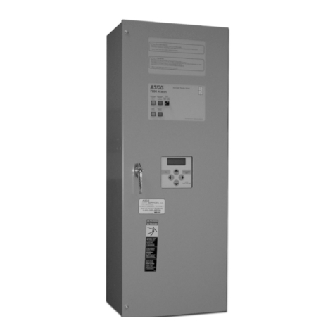
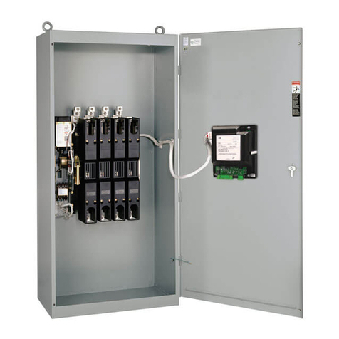
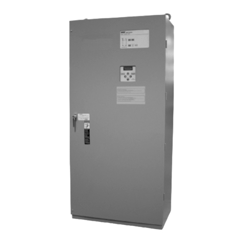
ASCO Series 2 0 C2000 Intelligent Controller (hereinafter referred to as Controller) is used to control the Series 2 0
transfer switch. The Controller is designed to control two sources. When either source has over voltage, low voltage,
failure, or abnormal frequency, the Controller will instruct the transfer switch to transfer to a better source or transfer to
the center-off position in order to protect the load.
Key Controller features include AC voltage & frequency signal acquisition, control signal input/output, user interface
(LCD display, LED indicator lights and keys), and RS485 communication (supporting MODBUS protocol).
The Controller appearance, functions and features, technical parameters, accessory configurations, and size of the
Controller will be described in this chapter.
1.1 Appearance
Please refer to Fig 1-1 for the appearance of the Controller.
Power
Connector
Signal
Connector
User ConnectorCorner Snap
ControllerController Operation Panel
Figure 1-1 Controller Appearance
1.2 Functions and Features
Detecting and displaying the voltages, frequencies and three-phase imbalance of two AC input sources, alarming
and displaying when failures occur as overvoltage, under-voltage, over frequency and under frequency, etc.
Multiple operating modes: Automatic (Source I Priority, No Source Priority), Remote Control, and Manual.
Center-off position delay and Center-off position protection modes.
Center-off position delay mode
When the transfer switch transfers the load from one source to another source, the transfer switch should stay in
center-off position for a period of time.
This time can be settable by user depending on the load characteristics. The default setting is 0 seconds, in
order to consume the load inertia and protect the load from getting damaged by the inrush current when the load
transfers from one source to another source.
Center-off position protection mode:
When there are abnormalities with both Source I and Source II, the transfer switch will transfer the load to the
center-off position to protect the load from getting damaged.
Built in abnormal transfer diagnosis capabilities in order to protect the transfer switch.
Utilizes high frequency switch power in order to have a wide input voltage range (80Vac~480Vac).
Capable of operating with DC 24V.
Many settable options, including over/under voltage, over/under frequency for both sources, and switching time
delays.
Configurable DI / DO Ports
