Xylem WTW Turb 750 IR/T User manual

OPERATING MANUAL
ba77234edfs03 08/2021
750 T
Turb
Turb®750 IR/T
LABORATORY TURBIDIMETER
OPERATING MANUAL

ba77234edfs03 08/2021
Turb®750 IR/T
Copyright ©2021 Xylem Analytics Germany GmbH
Printed in Germany.

Turb®750 IR/T Contents
3
Turb®750 IR/T - Contents
ba77234e03 08/2021
Safety . . . . . . . . . . . . . . . . . . . . . . . . . . . . . . . . . . . . . . . . . . . . . . . 4
Display and jack field. . . . . . . . . . . . . . . . . . . . . . . . . . . . . . . . . . . 4
Power supply . . . . . . . . . . . . . . . . . . . . . . . . . . . . . . . . . . . . . . . . . 5
General operating principles . . . . . . . . . . . . . . . . . . . . . . . . . . . . 5
Initial commissioning . . . . . . . . . . . . . . . . . . . . . . . . . . . . . . . . . . 8
Operation . . . . . . . . . . . . . . . . . . . . . . . . . . . . . . . . . . . . . . . . . . . . 9
Inserting a cell . . . . . . . . . . . . . . . . . . . . . . . . . . . . . . . . . . . . . . . . . . . 9
Preparing the cell and sample . . . . . . . . . . . . . . . . . . . . . . . . . . . . . . 9
Measuring the turbidity . . . . . . . . . . . . . . . . . . . . . . . . . . . . . . . . . . . 11
Calibration . . . . . . . . . . . . . . . . . . . . . . . . . . . . . . . . . . . . . . . . . . . . . 12
Maintenance, cleaning. . . . . . . . . . . . . . . . . . . . . . . . . . . . . . . . . 14
What to do if... . . . . . . . . . . . . . . . . . . . . . . . . . . . . . . . . . . . . . . . 16
General information . . . . . . . . . . . . . . . . . . . . . . . . . . . . . . . . . . . . . 16
Turbidity . . . . . . . . . . . . . . . . . . . . . . . . . . . . . . . . . . . . . . . . . . . . . . 16
Technical data . . . . . . . . . . . . . . . . . . . . . . . . . . . . . . . . . . . . . . . 17
General data . . . . . . . . . . . . . . . . . . . . . . . . . . . . . . . . . . . . . . . . . . . 17
Turbidity (Turb®750 IR) . . . . . . . . . . . . . . . . . . . . . . . . . . . . . . . . . . 18
Turbidity (Turb®750 T) . . . . . . . . . . . . . . . . . . . . . . . . . . . . . . . . . . . 19
All current data for the Turb®750 IR/T can be found on the Internet
under www.WTW.com:
Firmware
Operating manual
More detailed information can be found in the appendix of the
detailed operating manual on the CD-ROM provided.

Safety Turb®750 IR/T
4ba77234d03 08/2021
Safety
Safety information Safety instructions point out dangers:
NOTE
indicates a possibly dangerous situation where goods might be
damaged if the actions mentioned are not taken.
Safe operation
Authorized use This meter is authorized exclusively for turbidity measurements in the labo-
ratory.
Only the operation and running of the meter according to the instructions and
technical specifications given in this operating manual is authorized (see
TECHNICAL DATA, page 17).
Any other use is considered unauthorized.
Display and jack field
Display The graphic display shows all information of the current measurement in the
measured value display. The illumination enables to read the display even in
the darkness.
WARNING
indicates a possibly dangerous situation that can lead to se-
rious (irreversible) injury or death if the safety instruction is
not followed.
CAUTION
indicates a possibly dangerous situation that can lead to
slight (reversible) injury if the safety instruction is not fol-
lowed.
CAUTION
Danger of eye damage by visible and invisible LED radiation.
In the cell shaft of the Turb®750 IR there are light emitting
diodes (LEDs) of the 1M class.
Do not look at the radiation using optical instruments.
With normal, authorized use there is no hazard.

Turb®750 IR/T Power supply
5
ba77234d03 08/2021
Socket field
Power supply
The Turb®750 IR/T is supplied with power by the power pack included in the
scope of delivery. The batteries (4 batteries 1.5 V Mignon type AA) in the bat-
tery compartment supply the integrated clock with power when the power
supply is missing.
General operating principles
This section contains basic information on the operation of the Turb®750 IR/
T.
1 Status display indicators, e.g.:
[IRPC] = Intelligent reproducibility and plausibility check
[AQA] = Valid AQA check available
2 Measured value (with unit)
3 Status display indicators, e.g.
[3-P StdCAL] = Valid calibration available
(calibration type: 3-P StdCAL))
4 Status line with date and time
1
2
3
4
Turbidity
[IRPC] [AQA]
157.0
FNU
NTU
[3-P StdCAL]
15.01.20 16:12
1 USB-B (micro) interface
2 Power pack
3 RS232 serial interface
3
1 2

General operating principles Turb®750 IR/T
6ba77234d03 08/2021
Operating modes Measurement
The display indicates measurement data in the measured value display
Calibration
The display indicates a calibration procedure with calibration information
Data transmission
The meter transmits measuring datasets or calibration records to the inter-
face
Configuration
The display indicates a menu with further menus, settings and functions
Keypad <M (9)>Switch to the measured value display
<CAL (4)>Start calibration
<QuickCAL (1)>Start simplified calibration with one standard.
<AQA (2)>Start checking the meter with AQA standards
<A-Z (5)_> Select the entry mode in an entry field
Numerical or alphanumerical entry
<A-Z (5)>Display the next digit in an entry field with active
alphanumeric entry
(same function as <V (6) >)
<START/ENTER (.)>Open menus / confirm entries /
start measurement
<MENU (7)>Call up the Configuration menu
(all settings are made here)
<On/Off> Switch the meter on or off
<PRT (8)>Output display contents to RS232 or USB interface
(e.g. print)
<STO (0)>Open the Store menu: <STO (0) >
Quick storing: 2 x <STO (0) >
<STO (0) _> Open the measured value memory
<V (6)>, <W (3)> Highlight menu items or selection;
Set values
<ESC> Switch to the next higher menu level /
cancel input
Entering numerals with the number keys (see ENTERING NUMERALS
WITH THE NUMBER KEYS, page 8).

Turb®750 IR/T General operating principles
7
ba77234d03 08/2021
Measured value
display
In the measured value display, open the menu with <MENU (7) >.
Menus and dialogs The menus for settings and dialogs in procedures contain further subele-
ments. The selection is done with the keys <V><W>.
The current selection is displayed inverse.
Menus
The name of the menu is displayed at the upper edge of the frame. Menus
are opened by confirming with <START/ENTER (.) >. Example:
Settings
Settings are indicated by a colon. The current setting is displayed on the
right-hand side. With <START/ENTER (.) >, the selection of the possible
settings is opened. Subsequently, the setting can be changed with
<V><W> and <START/ENTER (.) >.
Example:
Functions
Functions are designated by the name of the function. They are immedi-
ately carried out when you confirm them with <START/ENTER (.) >.
Example: display the Calibr. record function
(in the Turbidity menu).
Messages
Information or operating instructions are designated by the i symbol.
Turbidity
Timer
System
Measured value memory
Configuration
Language:English
Info
Display
Reset
Interface
Continue...
System
Calibr. record
Calibr. type 3-P StdCAL
Calibr. interval:90 d
Standard 10.0 FNU/NTU
AQA
Reset
Turbidity

Initial commissioning Turb®750 IR/T
8ba77234d03 08/2021
They cannot be selected.
Example:
Entering numerals
with the number
keys
Keys with additional characters printed on (orange) are assigned doubly. In
the input fields you can directly enter digits with the orange number keys (e.g.
date and time). Complete entering a number with the key <START/ENTER
(.) >.
When entering numeric values with decimal separators (e.g. turbidity nominal
values), pressing <START/ENTER (.) > for the first time will set the decimal
separator. Pressing <START/ENTER (.) > for the second time will complete
the entering of the numeric value. The numeric value is always displayed with
decimal places and, if necessary, rounded.
Initial commissioning
Switching on the
meter
Press the <On/Off> key.
Setting the lan-
guage
The English language is set on delivery. Set a different language as follows:
Setting the date
and time Configuration The date and time are set in the menu,
/ System / Continue ... / Date/time.
i Insert standard
1000 FNU/NTU
i Press and hold <START>
i Align sample
Turbidity Calibration
The i indicates
info texts, e.g.
messages, notes or instruc-
tions
1 Open the Configuration menu with the <MENU (7) > key.
2 Open the Configuration / System / Language menu with the
<V><W> and <START/ENTER (.) > keys.
3 Select the required language with the <V><W> keys and confirm
with <START/ENTER (.) >.
4 Quit the menu with the <M (9) > key.

Turb®750 IR/T Operation
9
ba77234d03 08/2021
Operation
Inserting a cell
Before using a cell for the first time, determine and mark the suitable
measuring position for the cell (see PREPARING THE CELL, page 9).
Inserting a 28 mm
cell
Preparing the cell and sample
Preparing the cell Even completely clean quality cells exhibit tiny differences in their light trans-
mittance, e.g. inhomogeneities of the glass or small defects (e.g. scratches).
Therefore, guidelines for accurate and reproducible measurements (e.g. US
EPA) recommend that you always align the cell in the same way for
measuring with the aid of arrows printed on or markings. This refers to
sample cells and cells for calibration standards.
1 Push the dust cover (1) upward.
The cell shaft for 28 mm cells is open.
1
2 Insert the marked cell so that it is positioned on the bottom of
the cell shaft.
3 Align the cell marking (3) with the marking (4) of the cell shaft.
The cell is ready to be measured.

Operation Turb®750 IR/T
10 ba77234d03 08/2021
Prior to using a cell for the first time, the suitable position of the cell in the cell
shaft is determined and marked to make sure the optical path is not
disturbed. For the following measurements, the cell marking can just be
aligned with the meter marking.
The cell marking should be checked regularly and renewed as necessary.
The cell can be used until no suitable position for the optical path can be
found.
Determining a suit-
able position in the
cell shaft
Marking a cell
Preparing the sam-
ple
Air bubbles in the sample affect the measuring result to a massive extent
because they have a large scattering effect on the incident light. Larger air
bubbles cause sudden changes in the measured values whereas smaller air
bubbles are recorded by the instrument as turbidity. Therefore, avoid or
remove air bubbles:
During sampling, ensure all movement is kept to a minimum
If necessary, vent the sample (ultrasonic baths, heating or adding a sur-
We recommend that you do not treat any scratches in the cell
with oily liquids (not even with so-called "special silicone oils").
They could unnecessarily soil the meter and your working envi-
ronment. The optimum measurement accuracy is ensured by
aligning the cells. Scratched cells have to be replaced.
1 Clean the cell.
2 Stick the label for the marking onto the cell cap.
3 Fill the cell with a homogeneous solution (e.g. calibration standard
10.0 NTU).
4 Insert the cell.
5Press and hold the <START/ENTER (.) > key.
Turn the cell slowly and check the measured value:
– The measured value at the position should be no maximum.
– At the directly neighboring positions there should not be any
sudden changes of the measured values. The deviations of
measured values at the neighboring positions should not
exceed the following values:
Measured value < 1 NTU: max. +/- 0.02 NTU
Measured value > 1 NTU: max. +/- 2 %
6 Release the <START/ENTER (.) > key.
Measurement starts. The measured value is displayed.
7 Mark the determined position (aligning) of the cell on the label.
The cell is now prepared for all following measuring and calibration
actions.

Turb®750 IR/T Operation
11
ba77234d03 08/2021
face-active substance to reduce the surface tension)
Measuring the turbidity
NOTE
Never pour any liquids directly into the cell shaft. Always use a cell for
measurement. The meter only measures precisely if the cell is closed
with the black light protection cap and aligned with the marking of the
measuring position determined.
For quick and easy measuring we recommend that you use marked cells (see
PREPARING THE CELL, page 9).
If your cells are not marked you can determine the suitable position of the
individual cells in the cell shaft while measuring.
The outside of the cell always has to be clean, dry, and free of
fingerprints and scratches. Clean the cells before starting to
measure (see CLEANING THE CELLS, page 15). Only hold the cells
by the top or by the black light protection cap.
With turbidity values under 1 FNU/NTU, the measured value is
strongly influenced by the cell and its alignment.
To increase measurement accuracy with turbidity values under 1
FNU/NTU, calibration in the 0.02 FNU/NTU standard and later
measurement should take place in the same cell.
1 Clean the cell (see CLEANING THE CELLS, page 15).
2 Rinse the cell:
Pour approximately 10 ml sample into the cell. Close the cell and
rotate it several times before throwing the sample away.
3 Repeat the rinsing procedure twice more.
4 Fill the cell with the sample to be measured (approx. 15 ml). Close
the cell with the black light protection cap.
5 Insert the cell.
6 Align the marking on the cell cap with the marking at the cell shaft.
or
Determine the suitable position of the cell in the cell shaft (see
DETERMINING A SUITABLE POSITION IN THE CELL SHAFT, page 10).
7 Press the <START/ENTER (.) > key.
Measurement starts. The measured value is displayed.

Operation Turb®750 IR/T
12 ba77234d03 08/2021
Intelligent repro-
ducibility and plau-
sibility check
(IRPC)
With the intelligent reproducibility and plausibility check (IRCP) a multiple
measurement is carried out, evaluated and, by eliminating the outliers, the
plausible measured value is indicated on the display.
The intelligent reproducibility and plausibility check (IRPC) is active with all
measurements. It is displayed in the upper status line [IRPC].
Calibration
When to calibrate? Routinely within the framework of the company quality assurance
When the calibration interval has expired
With a temperature change
Preparing the cali-
bration
For quick and easy measuring we recommend that you use marked cells with
the calibration standards (see PREPARING THE CELL, page 9).
If your cells are not marked you can determine the suitable position of the
individual cells in the cell shaft while measuring.
Perform the following preparatory activities when you want to calibrate:
The measured value is automatically output to the inter-
faces.
8 Repeat the steps 2 to 8 for further samples.
Turbidity
[IRPC] [AQA]
157.0
FNU
NTU
[3-P StdCAL]
15.01.20 15:12
1 Select the calibration type (menu Configuration / Turbidity / Calibr.
type.).
For QuickCAL calibration with the <QuickCAL (1) > key, the
setting of the QuickCAL calibration type and limitation of the
measuring range are done automatically.
2 Clean the cell (see CLEANING THE CELLS, page 15).
3 Insert the cell (see INSERTING A CELL, page 9).

Turb®750 IR/T Operation
13
ba77234d03 08/2021
Carrying out a cali-
bration (example:
3-P StdCAL)
4 Press the <CAL (4) > key.
The guided calibration with the selected calibration type starts.
Follow the instructions on the display.
5 Insert the cell with the displayed calibration standard (here e.g. 1000
FNU/NTU) in the cell shaft.
6 Align the marking on the cell cap with the marking at the cell shaft.
or
Determine the suitable position of the cell in the cell shaft (see
DETERMINING A SUITABLE POSITION IN THE CELL SHAFT, page 10).
7 Release the <START/ENTER (.) > key.
Measurement of the calibration standard begins.
Before measuring the third calibration standard of 0.02 FNU/NTU
you can exit the calibration with <ESC> at any time.
The new calibration data are discarded. The old calibration data
are used.
8 Repeat the steps 4 - 6 with the calibration standards 10.00 FNU/NTU
and 0.02 FNU/NTU.
After measuring the 0.02 FNU/NTU calibration standard, the calibra-
tion result is displayed.
The calibration is complete.
9 Confirm the calibration result with <START/ENTER (.) >.
The calibration record is displayed.
10 Confirm the calibration record with <START/ENTER (.) >.
The display shows instructions for the first measurement.
The valid calibration is indicated on the display as a status, e.g. [3-P
StdCAL].
i Insert standard
1000 FNU/NTU
i Press and hold <START>
i Align sample
Turbidity Calibration
i Turb. = 1000 FNU/NTU
i Start calibration
by releasing <START>
Turbidity Calibration

Maintenance, cleaning Turb®750 IR/T
14 ba77234d03 08/2021
Calibration record At the end of each calibration procedure a calibration info (i symbol) and the
calibration record is displayed.
For each calibration type the last calibration is stored in the calibration
memory.
Maintenance, cleaning
Maintenance The meter is almost maintenance-free.
The only maintenance task is replacing the batteries.
NOTE
Make sure that the poles of the batteries are positioned correctly.
The ± signs on the batteries must correspond to the ± signs in the
battery compartment.
i Insert sample
i Press and hold <START>
i Align sample
[3-P StdCAL]
Turbidity
1 Open the battery compartment (1) on the underside of the meter.
1 Battery compartment
2 Place four batteries (type Mignon AA) in the battery compartment.
3 Close the battery compartment (1).
1

Turb®750 IR/T Maintenance, cleaning
15
ba77234d03 08/2021
Cleaning Occasionally wipe the outside of the measuring instrument with a damp, lint-
free cloth. Disinfect the housing with isopropanol as required.
NOTE
The housing components are made of synthetic materials (polyure-
thane, ABS and PMMA). Thus, avoid contact with acetone and similar
detergents that contain solvents. Remove any splashes immediately.
Cleaning the cell
shaft
If liquid is in the cell shaft (e.g. due to a spilled cell), clean the cell shaft as
follows:
Cleaning the cells Cells have to be clean, dry, and free of fingerprints and scratches. Therefore,
clean them regularly:
4 Set the date and time
1 Switch the Turb®750 IR/T off and pull out the power plug.
2 Rinse the cell shaft with distilled water.
1 Clean the cells inside and out with hydrochloric acid or laboratory
soap.
2 Rinse several times with distilled water.
3 Let them dry in the air.
4 Only hold the cells by the top or by the light protection cap so that the
optical path is not impaired.
5 Before measuring, clean the cell with the enclosed cleaning cloth.
Scratches in the glass change the optical characteristics of the
cell and falsify the measured value. For this reason, never use
scratched cells!

What to do if... Turb®750 IR/T
16 ba77234d03 08/2021
What to do if...
General information
Display, LoBat
Meter does not
react to keystroke
Error message
iAQA not
activated!
Error message,
Error
0, 8, 16, 16384
You want to know
which software
version is in the
meter
Turbidity
Error message
Measured values
obviously incor-
rect
Cause Remedy
– Batteries almost empty – Insert new batteries
Cause Remedy
– Software error
– Operating condition undefined
or EMC load unallowed
– Processor reset:
Press the <START/ENTER (.) >and
<PRT (8) >keys simultaneously.
Cause Remedy
– The function AQA was not
activated.
– Activate the AQA check
Cause Remedy
– Instrument error – Repeat measurement
– Meter defective,
contact the service department
Cause Remedy
– E.g., a question by the service
department
– Switch on the meter.
– Open the menu Configuration/
System / Info. The instrument data
are displayed.
Cause Remedy
– Cell not correctly inserted – Lock the cell into place
– Cell contaminated – Clean the cell
– Calibration too old – Carry out calibration

Turb®750 IR/T Technical data
17
ba77234d03 08/2021
Measured value
display
< 0.01 FNU/NTU
Technical data
General data
Cause Remedy
– Calibration defective – Carry out calibration
– Measured value outside the
measuring range
– Not possible
Dimensions Approx. 290 x 190 x 80 mm
Weight Approx. 1.0 kg
Mechanical structure Type of protection IP 43
Electrical safety Protective class III
Test certificates CE
Ambient conditions Storage -25 °C... +65 °C
Operation +5 °C ... +40 °C
Admissible relative
humidity
Yearly mean: < 75 %
30 days/year: 95 %
Other days: 85 %
Power supply Batteries 4 x 1.5 V alkali-manganese batteries, type
AA
Power pack ShenZhen RiHuiDa Power Supply Co Ltd
RHD20W090150
Input: 100... 240 V ~ / 50... 60 Hz / 400 mA
Output: 9 V = / 1.5 A
Connection max. overvoltage category II
Primary plugs Primary plugs included in the scope of deliv-
ery:
Euro, US, UK and Australian.

Technical data Turb®750 IR/T
18 ba77234d03 08/2021
Turbidity (Turb®750 IR)
Serial
interface
(printer)
Connection of the cable AK 540/B or AK 540/S
Baud rate Adjustable:
1200, 2400, 4800, 9600, 19200 baud
Type RS232
Data bits 8
Stop bits 2
Parity None
Handshake RTS/CTS
Cable length Max. 15 m
USB interface
(PC)
Type USB 1.1
USB-B (Device), PC
Baud rate Adjustable:
1200, 2400, 4800, 9600, 19200 baud
Data bits 8
Stop bits 2
Parity None
Handshake RTS/CTS
Cable length max. 3 m (9.843 feet)
Guidelines
and norms used
EMC EC directive 2014/30/EC
EN 61326-1
FCC Class A
Meter safety EC directive 2014/35/EC
EN 61010-1
IP protection class EN 60529
Measuring principle Nephelometric measurement according to DIN EN ISO 7027
Light source Infrared LED

Turb®750 IR/T Technical data
19
ba77234d03 08/2021
Turbidity (Turb®750 T)
Calibration 3-P StdCAL QuickCAL FreeCAL
Measuring range
depending on the calibra-
tion type
0.01... 1100 FNU/NTU 0 - 40 FNU/NTU lowest - highest stan-
dard FNU/NTU
Resolution In the range
0.01... 9.99 FNU/NTU
max. 0.01 FNU/NTU
In the range
10.0... 99.9 FNU/NTU
max. 0.1 FNU/NTU
In the range
100... 1100 FNU/NTU
max. 1 FNU/NTU
Accuracy In the range
0... 1100 FNU/NTU
± 2 % of the measured value
or ± 0.01 FNU/NTU
Repeatability 0.5% of the measured
value
Response time 4 seconds
Measuring principle Nephelometric measurement according to US EPA 180.1
Light source White light tungsten lamp
Calibration 3-P StdCAL QuickCAL FreeCAL
Measuring range
depending on the calibra-
tion type
0.01... 1100 NTU 0 - 40 NTU lowest - highest stan-
dard NTU
Resolution In the range
0.01... 9.99 NTU
max. 0.01 NTU
In the range
10.0... 99.9 NTU
max. 0.1 NTU
In the range
100... 1100 NTU
max. 1 NTU

Technical data Turb®750 IR/T
20 ba77234d03 08/2021
Accuracy In the range
0... 500 NTU
± 2 % of the measured value
or ± 0.01 NTU
In the range
500... 1100 NTU
± 3% of measured value
Repeatability 1% of the measured
value
Response time 7 seconds
Other manuals for WTW Turb 750 IR/T
2
Table of contents
Other Xylem Laboratory Equipment manuals
Xylem
Xylem SI Analytics TO 7280 User manual

Xylem
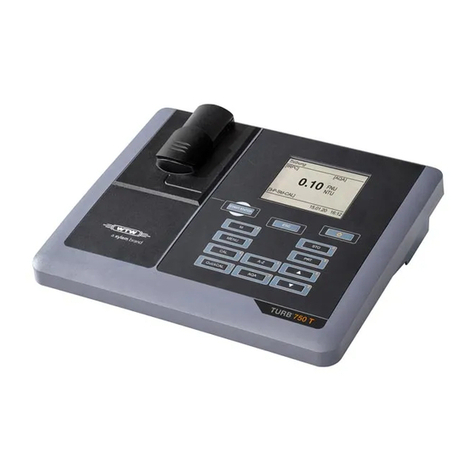
Xylem WTW Turb 750 IR/T User manual
Xylem
Xylem WTW OxiTop Box User manual

Xylem
Xylem SI Analytics TitroLine 5000 User manual
Xylem
Xylem SI Analytics TitroLine 6000 User manual

Xylem
Xylem YSI 910 COD User manual

Xylem
Xylem SI Analytics TITRONIC 500 User manual

Xylem
Xylem TitroLine 7800 User manual
Popular Laboratory Equipment manuals by other brands

Isotech
Isotech Saturn 877 User maintenance manual/handbook

Gema
Gema OptiFlow IG06-BN Operating instructions and spare parts list

PerkinElmer
PerkinElmer Lambda 650 Hardware guide

Star Lab
Star Lab ErgoOne E user manual

Exor
Exor JSPOU0P1 installation guide

Thermo Scientific
Thermo Scientific iCAP 7000 Series manual