ASHE CONTROLS PRIVATE LIMITED.
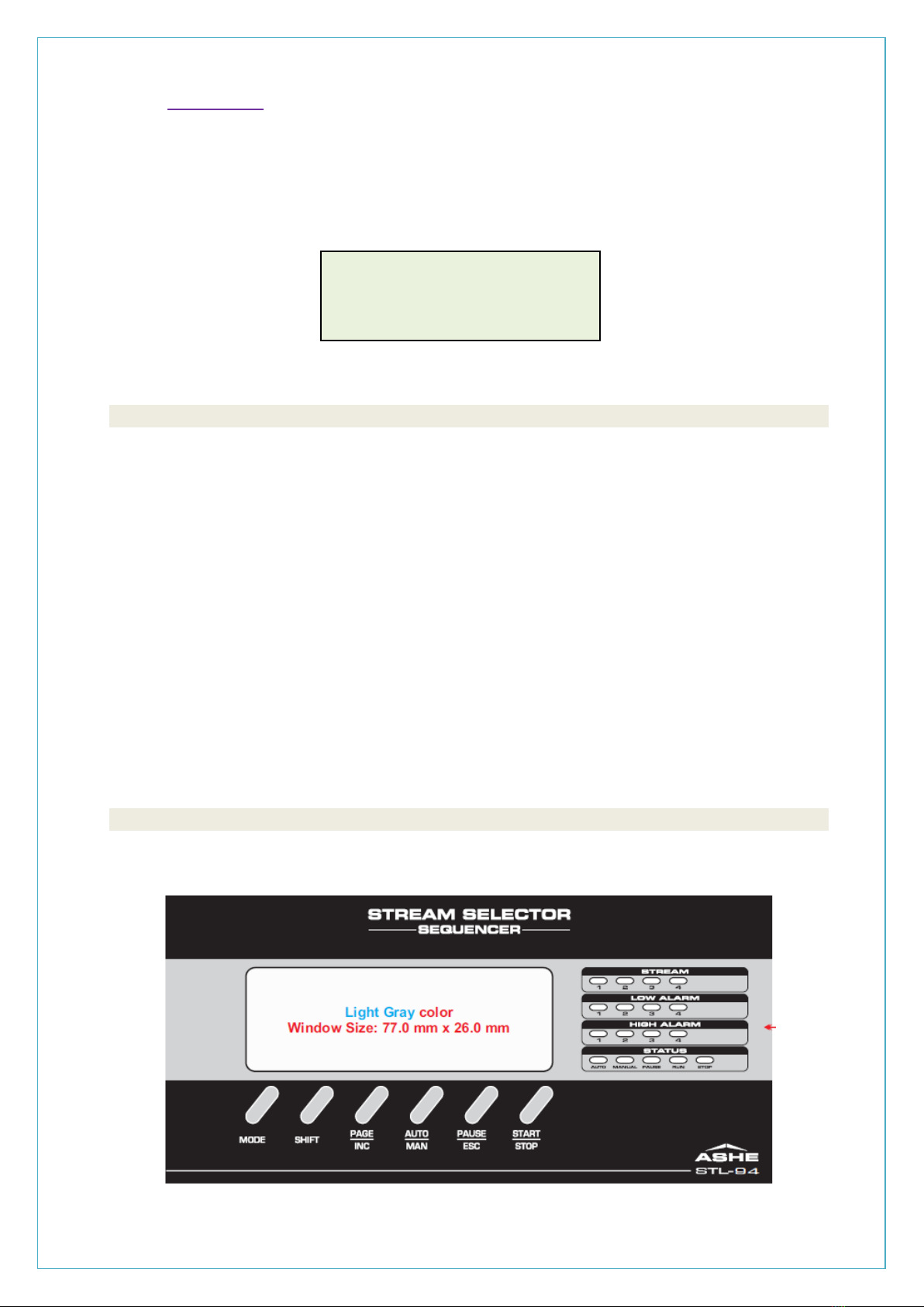
STREAM SELECTOR STL-94
Operation Manual
5. AUTO MODE
The instrument STL-94 can be operated automatically by means of the key on the front keypad. When
the instrument is in AUTO MODE, the AUTO LED on the front panel will glow.
The Stream selection is done by the internal microcontroller as per user settings.
The AUTO MODE is available in both modes of operation, viz: Timer and Pulse Modes.
a. TIMER MODE
The ASHE Stream Selector instrument can be operated in Timer Mode.
In the Setting mode, the operator can select the number of Streams to be run at Power ON.
The particular undesired Stream can be skipped in the Skip menu. For the unskipped Streams,
the timer value can be set in seconds.
The following sequence is to be carried out in the Timer Auto mode: -
1) Press the RUN key to start the process.
2) The process will start from the first unskipped Stream.
3) The relay for the current Stream gets energized.
4) The display shows the remaining time for the current Stream.
5) When the timer value becomes zero, the instrument switches over to the next unskipped
Stream.
6) This cycle goes on until the last unskipped Stream and then goes back to the first stream.
b. PULSE MODE
The ASHE Stream Selector instrument can also be operated in Pulse Mode.
In the Setting mode, the operator can select the number of Streams to be run at Power ON.
The particular undesired Stream can be skipped in the Skip Menu. For the unskipped streams,
the timer value can be set in seconds.
The following sequence is to be carried out in the Timer auto Mode: -
1) Press the RUN key to start the process.
2) The process will start from the first unskipped Stream.
3) The relay for the current Stream gets energized.
4) The display shows the sample time for the current Stream.
5) The instrument waits for a synchronizing pulse from the Analyzer.
6) As soon as the +12V pulse is received, the instrument stops sampling of the current
Stream.
7) The instrument switches over to next Stream at the falling edge of the synchronizing pulse.
8) This cycle goes on until the last unskipped Stream and then goes back to the first stream.