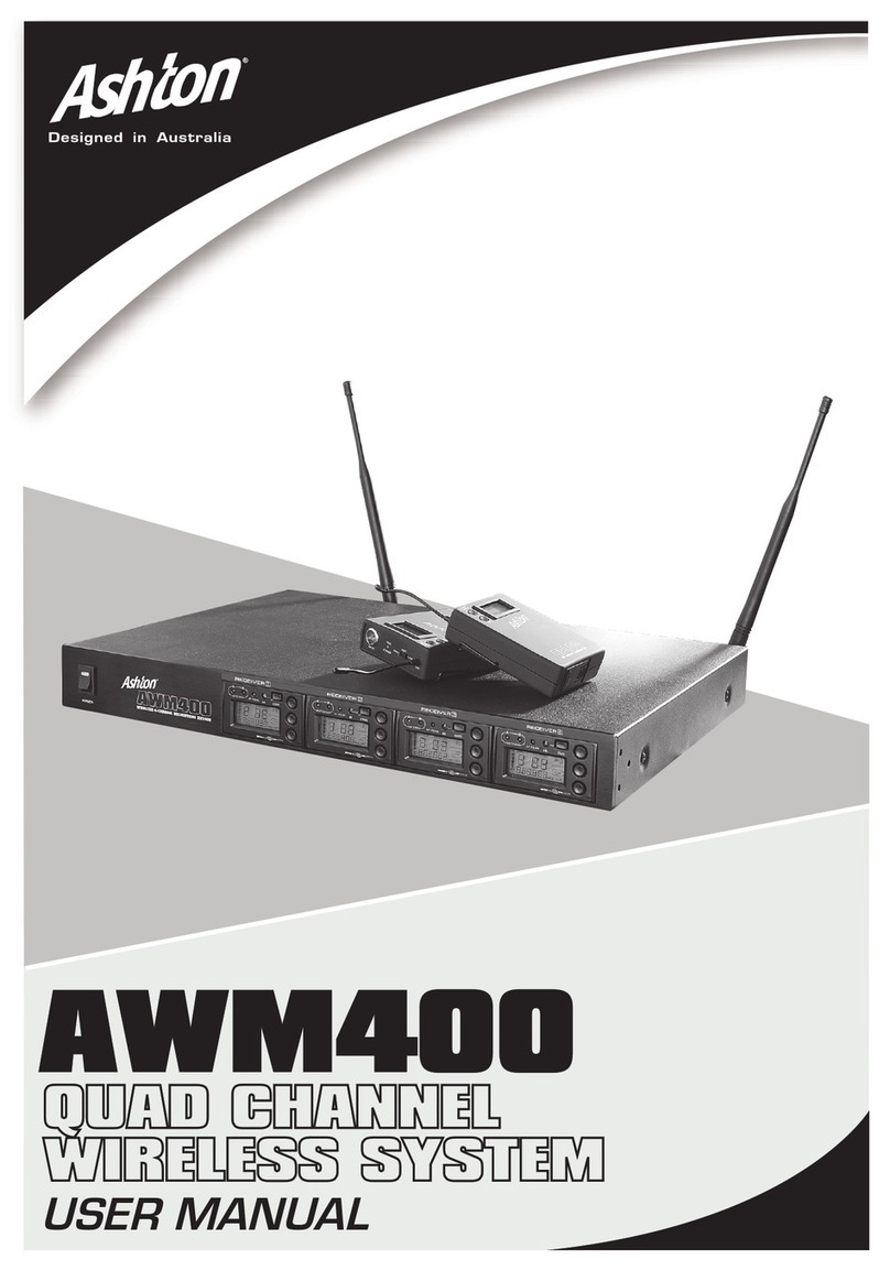
Ashton AWM250 User manual

1
User Manual

2
Care Instructions........................................................................................................................................................... 3
Product Specifications ................................................................................................................................................. 4
Instructions For Use ..................................................................................................................................................... 5
Troubleshooting............................................................................................................................................................ 6
Specific Product Features: AWM250 ........................................................................................................................... 7
Specific Product Features: AWM350 ........................................................................................................................... 9
Specific Product Features: Handheld Transmitter........................................................................................................ 11
Specific Product Features: Bodypack Transmitter........................................................................................................ 12
Product Notes: ............................................................................................................................................................. 13
INDEX

3
When using any electronic product the following basic precautions should always be adhered to:
1. Read all the safety and installation instructions, explanations of graphic symbols and set-up / controls
before using any product.
2. This product must be earthed. In the unlikely event of malfunction or breakdown, grounding provides
a path of least resistance for an electric current, which reduces the risk of electric shock. This product
is equipped with a cord featuring an equipment-grounding conductor and a grounding plug. The plug
must be connected to an appropriate outlet that is properly installed and earthed in accordance with
all local codes and regulations.
DANGER: Improper connection of the equipment grounding conductor can result in a risk of electric
shock. Check with a qualified electrician or service professional if you are in doubt as to whether the
product is properly grounded. Do not modify the plug provided with the product. If the plug does not
fit the outlet, have a proper outlet installed by a qualified technician.
3. To reduce the risk of injury, close supervision is necessary when the product is used, especially
near children.
4. Do not use this product near water: eg. near a bathtub, sink, in a wet basement or near a swimming pool.
5. This product, either alone or in combination with an instrument and headphones or speakers, may be capable of
producing sound levels that could cause permanent hearing loss. Do not operate for a long period of time at a high
volume level, or at a level that is uncomfortable.
6. This product should be installed and used in a location that provides adequate ventilation.
7. This product should be located away from heat sources, such as radiators, heat registers, or other
products or circumstances that produce heat.
8. This product should be connected to a power supply only of the type described in the operating
instructions or as marked on the product.
9. The power supply cord of the product should be unplugged from the outlet when left unused for a long period of
time. When unplugging the power supply cord, do not pull on the cord but grasp it by the plug.
10. Care should be taken to ensure that objects and liquids do not enter the enclosure through any openings.
11. The product should be serviced by qualified service personnel when:
A. The power supply cord, or the plug, has been damaged.
B. Objects have fallen on, or liquid has been spilled into, the product.
C. The product has been exposed to rain or moisture.
D. The product has been dropped or damaged.
E. The product does not appear to be operating normally, or exhibits a marked change in performance
12. Do not attempt to service the product beyond what is described in the manual instructions. All other
servicing should be referred to qualified service personnel.
13. Do not place objects on the product, the power cord, or place it in a position where anyone could trip over, walk
on, or roll anything over it. Do not allow any part of the product to rest on, or be installed
over, power cords of any type. Improper installations of this type create the possibility of fire and a general safety
hazard.
WARNING
IMPORTANT NOTE: To reduce the risk related to the correct and normal use of the product, all Ashton products are
accurately tested in a safety laboratory. Do not modify the present unit, the safety standard and the instrument’s
performance could be compromised, and as a further consequence the warranty
will be revoked.

4
MAX AUDIO INPUT LEVEL
0dBV
DIMENSIONS
245mm x 51mm diameter
WEIGHT
315 grams (without batteries)
POWER REQUIREMENTS
2 x AA” size alkaline or rechargeable batteries
BATTERY LIFE
>6 hours
AUDIO OUTPUT LEVEL
(=/- 30KHZ DEVIATION, 1KHZTONE)
XLR Connector (into 600Ωload): -12dBV
1/4 Inch Connector (into 3000Ωload): -18dBV
OUTPUT IMPEDENCE
XLR connector: 200Ω
1/4 inch connector: 1KΩ
XLR OUTPUT
Impedance balanced
Pin 1: Ground (cable shield)
Pin 2: Audio
Pin 3: No Audio
SENSITIVITY
-94dBm for 30dB SINAD, typical
IMAGE REJECTION
>55dB
DIMENSIONS
AWM250: 44mm (H) x 410mm (W) x 180mm (D)
AWM350: 45mm (H) x 482mm (W) x 160mm (D)
WEIGHT
2500 grams
POWER REQUIREMENTS
12-18V DC at 300mA, supplied by external
power supply.
SPECIFICATIONS
SYSTEMHANDHELD TRANSMITTER
RECEIVER TRANSMITTER
FREQUENCY RANGE &
TRANSMITTER OUTPUT LEVEL
Band: UD
Transmitter Output Level: 10dBm
OPERATING RANGE UNDER
TYPICAL CONDITIONS
50m - Note: Actual range depends on RF signal
absorption, reflection and interference
AUDIO FREQUENCY RESPONSE
(+/-3DB) 70Hz~16KHz
TOTAL HARMONIC DISTORTION
(+/-30KHZ DEVIATION, 1KHZTONE) <1%
DYNAMIC RANGE
>90dBA - weighted
OPERATING TEMPERATURE RANGE
-10ºC to +50ºC
Note: Battery characteristics may limit this range
BODYPACK TRANSMITTER
MAX AUDIO INPUT LEVEL
0dBV to +10dBV
GAIN ADJUSTMENT RANGE
20dB
INPUT IMPEDANCE
5KΩ
DIMENSIONS
85mm (H) x 65mm (W) x 24mm (D)
WEIGHT
87 grams (without batteries)
POWER REQUIREMENTS
2 x AA” size alkaline or rechargeable batteries
BATTERY LIFE
>6 hours

5
5. The receiver features an electronic volume
control system. Press the or button to adjust
the output volume incrementally on the receiver.
(Diagram 4)
4. Press the SET button until ADD flickers, then press
or key to select the number to add.
NOTE: Multiple occurrences of the same number
cannot be used when multi-systems are in use.
INSTRUCTIONS FOR USE
PAIRING TRANSMITTER / RECEIVER
3. Press the SET key until GROUP flickers.
Press or key to select suitable group number
(Diagram 1). Press the SET key again until MANU-
AL CHANNEL flickers. Press or key
to select the suitable channel. (Diagram 2)
NOTE: When multi-systems are in use, all systems
must be set to the same group number. Select an
exclusive channel for each system in the same group.
1. Take transmitter out of box. Screw the antenna into
A and B Jacks. Plug audio cable into channel XLR
output socket and connect other end into desired
speaker or other output source. Place all applicable
batteries into receivers.
2. Plug power cable into transmitter. Make sure
output source is powered on.
6. Indicates the working frequency. (Diagram 5)
1. Turn ON the transmitter, point the IR window
of receiver to the IR window of the transmitter.
2. Press the ASC key on the receiver. Keep the IR
window of the receiver pointed at the IR window
of the transmitter, then press the ASC key
of the transmitter.
3. Press the ASC key of the receiver, this will
broadcast the signal for 25 seconds - INFRARED
will flicker on the display. (Diagram 6)
4. Turn on the handheld transmitter or press
the ASC key on the body pack, the transmitter
will broadcast the signal for 25 seconds.
This will pair the two devices.
5. The LCD of the transmitter will flicker when
IR connection is enabled, as will the IR symbol
on the LED.
NOTE: When establishing an IR connection between
the receiver and the transmitter, the distance
between them should not exceed 50cm. When more
than one system is in use, only one transmitter IR
window should be pointed to the receiver at any
given time.

6
TROUBLESHOOTING
PROBLEM LED STATUS SOLUTION
No sound or faint
sound
The LED of the transmitter is off Slide the transmitter’s power switch to ON. Make
sure battery terminals match transmitter terminals.
The LED of the receiver is off Make sure to attach the power adaptor to the DC
input in the back of the receiver and attach the
other end to a wall power socket. Check whether
the wall power socket and voltage supply is
normal.
The RF LED of the receiver
is illuminated
Turn up the volume of the receiver. Turn up the
gain of the transmitter. Check the cable connection
between the receiver and amplifier or between the
receiver and mixer.
The RF LED of the receiver
is off, but the LED of the
transmitter remains on
Put the receiver away from any metallic object,
check whether there is an obstruction between
the transmitter and receiver. Ensure that the
transmitter and the receiver are tuned to the same
frequency.
The battery life LED is flickering Replace the battery of transmitter.
Distortion of noise The LED display of the receiver
indicates the antenna is valid
Make sure the receiver is a reasonable distance
away from the RF generating equipment, such as
a CD player, computer and digital signal processor.
Change the frequency of the transmitter and
receiver. Turn down the gain of the transmitter.
Replace the battery
of the transmitter. Increase the bandwidth
of frequency when multi-systems are in use.
Distortion level
increases gradually
The battery life LED is flickering Replace the battery of the transmitter.
Sound level from the
receiver is different
from that of a cabled
guitar or microphone
Adjust transmitters gain and receivers volume
as necessary.

7
8. System setting button
9. Infrared (IR) port
10. Sync button
AWM250 PANEL FRONT
AWM250 PANEL BACK
1. Power Switch
2. Channel receiving LED
3. Channel RF LED
1. Antenna jack B
2. Channel XLR output socket
3. 1/4 inch mix output socket
4. Channel AF LED
5. Channel LCD
6. Menu up select button
7. Menu down select button
4. Channel mute-level adjust button
5. AC power input
6. Antenna jack A
UP
DOW N
SET
POWER
ANTENNA B ANTENNA A
XLR BALANCED - 12dBV
UNBAL MUTE LEVELAF OUTPUT
DC INPU T
12-18V in
500m A
Many regions have strict management on the
frequency of the radio. This system provides
several bandwidth selections:
UA: 518 – 548MHz UB: 630– 660MHz
UC: 740 – 770MHz UD: 800 – 822MHz
UE: 838– 865MHz
The system presets multi-group and channel
to avoid RF interference. Adjust the channel
of the system when multi–use receivers are
in use. There are approximately 16 units of
receivers/transmitters in use in one bandwidth.
• Maintain a line of sight between the transmitter and
receiver.
• Keep the receiver more than 1m from the ground,
avoid placing it close to walls.
• Try to avoid setting up the wireless system around
appliances that cause interference,
such as TV, radio and other wireless appliances.
• Avoid placing the receiver near metal or RF generat-
ing equipment such as CD players,
computers & digital signal processors.
AWM250 PRODUCT USE TIPSAWM250 FREQUENCY SELECTION

8
The AWM250 system components include:
1. Receiver
2. AA batteries
3. Audio cable
4. Power adaptor
5. Antenna
Guitar System includes:
1. Bodypack transmitter
2. 1/4’ connector and
mini 3-plug in
Bodypack Transmitter:
1. Transmitter
2. Headset Microphone
3. Lapel
Handheld Transmitter:
AWM250 SYSTEM COMPONENTS

9
11. Signal send button
12. Infrared (IR) window -
sends the IR signal
to transmitter
13. Monitor phone jack
14. Monitor volume button
AWM350 PANEL FRONT
AWM350 PANEL BACK
1. Power Switch
2. Channel A receiving
3. Channel A RB LED
4. Channel B RF LED
5. Channel B receiving LED
6. Channel 1 AF LED
7. Channel 1 LCD
8. Menu up select button
9. System setting button
10. Menu down select button
Many regions have strict management on the
frequency of the radio. This system provides
several bandwidth selections:
UA: 518 – 548MHz UB: 630 – 660MHz
UC: 740 – 770MHz UD: 800 – 822MHz
UE: 838 – 865MHz
The system presets multi-group and channel
to avoid RF interference. Adjust the channel
of the system when multi-use receivers are
in use. There are approximately 16 units of
receivers/transmitters in use in one bandwidth.
• Maintain a line of sight between the transmitter and
receiver.
• Keep the receiver more than 1m from the ground,
avoid placing it close to walls.
• Try to avoid setting up the wireless system around
appliances that cause interference,
such as TV, radio and other wireless appliances.
• Avoid placing the receiver near metal or RF generat-
ing equipment such as CD players,
computers & digital signal processors.
AWM350 PRODUCT USE TIPSAWM350 FREQUENCY
RF
A
6 +3
+6
5
4
3
2
1
0
-3
-5
-10
-20
B
AFRF
A
6 +3
+6
5
4
3
2
1
0
-3
-5
-10
-20
B
AF
SET SET
ASC
POWER
IR
PHONES
ASC
1. Antenna B jack
2. Channel 2 mute-level
3. 1/4” mix output socket
4. XLR mixoutput socket
5. Channel 2 XLR output socket
6. Channel 1 XLR output socket
7. Channel 1 mute-level adjust
8. AC power input
9. Antenna A

10
RF
A
6 +3
+6
5
4
3
2
1
0
-3
-5
-10
-20
B
AFRF
A
6 +3
+6
5
4
3
2
1
0
-3
-5
-10
-20
B
AF
SET SET
ASC
POWER
IR
PHONES
ASC
The AWM350 system components include:
1. Receiver
2. AA batteries
3. Audio cable
4. Power adaptor
5. Antenna
Guitar System includes:
1. Bodypack transmitter
2. 1/4’ connector and
mini 3-plug in
Bodypack Transmitter:
1. Transmitter
2. Headset Microphone
3. Lapel
Handheld Transmitter:
AWM350 SYSTEM COMPONENTS

11
FUNCTIONS
1. Grill
2. LCD display
3. Power switch
Power ON / OFF the transmitter.
4. MUTE button
Touch to change between MUTE active status.
5. IR Port
Match the frequency between this product and
the receiver to match levels.
Each product will occupy one infrared
port when multi-system is in use.
6. Power adjust button
Do not alter unless necessary.
a. MUTE Setting
Press for 2 seconds, the transmitter will flash MUTE,
GROUP and CHANNEL. Touch the mute button to
enable / disable MUTE.
b. Lock / Unlock Transmitter
Press mute and menu button to lock / unlock the
current setting. When locked, the settings cannot be
adjusted manually. The lock setting does not alter the
IR receiver settings.
c. Battery Display
Indicates the current power level.
d. Master List Display
Indicates the master frequency in use.
The master settings cannot be changed
using the transmitter.
e. Incompatible Warning
Indicates the receiver and transmitter have
been set to an incompatible frequency band. Please
contact your local dealer for assistance.
HANDHELD TRANSMITTER SPECIFICATIONS

12
a. Selecting a GROUP or CHANNEL
1. Hold the select button until GROUP and
CHANNEL display alternately on screen.
2. Release to press select button when
GROUP (a) is on display. This will enable
a change in frequency. When GROUP is
flashing, press select button to set the
frequency by one.
3. Release to press select button when
CHANNEL (b) is on display. This will enable
a change in frequency. When CHANNEL
is flashing, press select button to set the
frequency by one.
c. Battery Display
Indicates the current power level of the battery.
d. Frequency Display
Indicates the master frequency in use.
FUNCTIONS
1. Antenna
2. LCD display
3. Power
Hold to change power ON / OFF
4. POWER / IR indicator
Green: Active
Flashing Red: IR transmitting enabled
Solid Red: Low battery power
5. Mic in
6. Channel selection button
7. Audio volume adjust
Do not alter unless necessary
8. IR Port
Match the frequency between this product
and the receiver to match levels. Each product will
take one infrared port when multi-system
is in use.
BODYPACK TRANSMITTER SPECIFICATIONS

This manual suits for next models
1
Table of contents
Other Ashton Microphone System manuals
Popular Microphone System manuals by other brands

Audio Technica
Audio Technica AT895 Installation and operation

MikroTik
MikroTik Routerboard NetMetal 5 user manual

Nady Systems
Nady Systems DKW-3 operating instructions

Audio Technica
Audio Technica ATW-600 User information

Audio2000's
Audio2000's AWM6951 owner's manual

Sennheiser
Sennheiser EW 512 G3 Product sheet