5
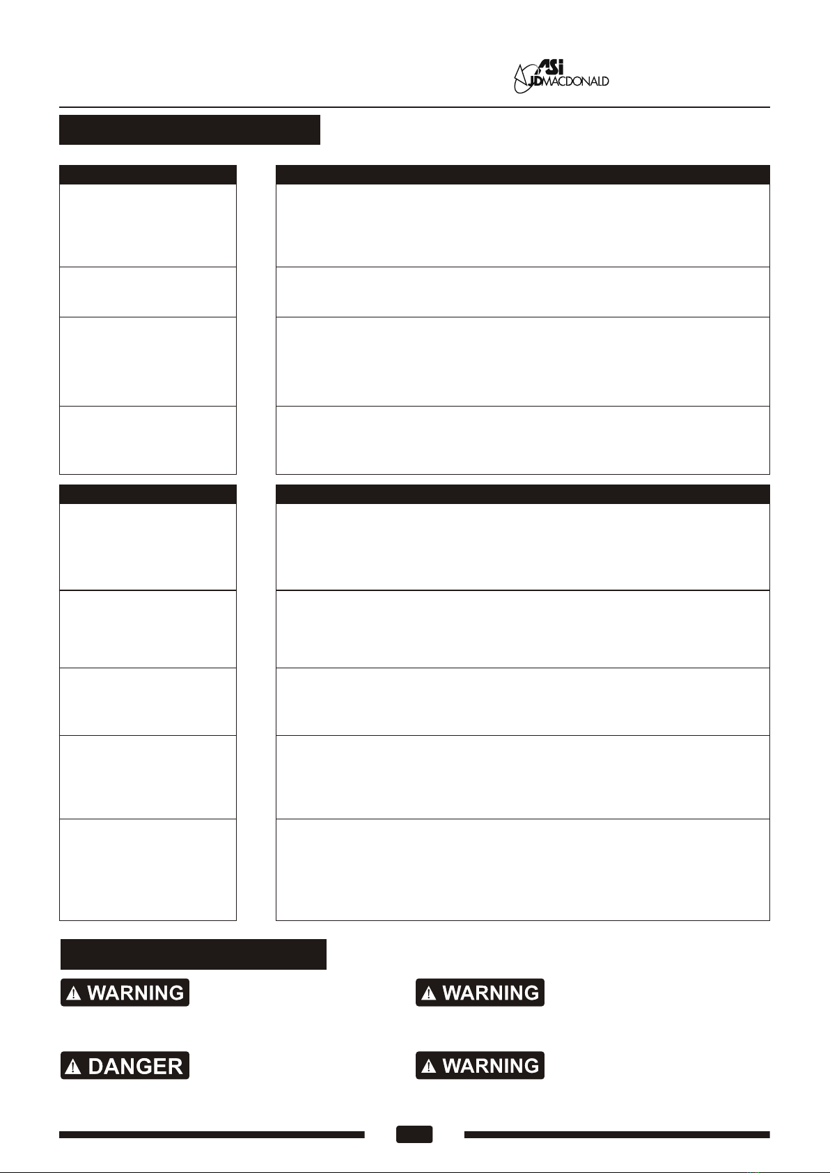
Diagnostics and Remedies
If the dryer will not run
The dryer cycles by itself
or runs constantly
The dryer runs but air
stream is low pressure
and/or low velocity
Ensure that there is no obstruction on or in front of the IR sensor. Clean
any dirt or debris off the sensor lens. If problem persists, replace sensor.
First ensure that the breaker supplying the dryer is operational. If it is,
disconnect the power and remove the dryer cover. Taking suitable
precautions to avoid shock hazard, reconnect the power and check for
Voltage at the terminal block. Verify that connections are made correctly.
Ensure that the supply Voltage is correct. Dryer will run weakly if the
input Voltage is too low. Verify Voltage requirement on unit rating label
and correct supply as required.
The dryer makes a loud
noise and does not run
for a complete cycle
Ensure that the supply Voltage is correct. Dryer will make a loud humming
noise if the input Voltage is too high. Verify Voltage requirement on unit
rating label and correct supply as required. If CBM has been damaged,
replace CBM, IR sensor module.
Symptom Corrective Actions for Initial Installation Failures
Symptom Corrective Actions for In-Service Failures
If the dryer will not run
The IR sensor only “sees”
close range objects
The dryer only blows cold
air during a full cycle
Ensure that there is no obstruction on or in front of the IR sensor. Clean
any dirt or debris off the sensor lens. If problem persists, disconnect the
power and remove the dryer cover and replace CBM, IR sensor module.
First ensure that the breaker supplying the dryer is operational. If it is,
disconnect the power and remove the dryer cover. Replace the CBM
and IR sensor module. Taking suitable precautions to avoid shock
hazard, reconnect the power and check for Voltage at the terminal block.
Disconnect the power. Remove the dryer cover and check/ ensure heater
SW is ON. Disassemble the blower-motor/fan housing. Test the thermostat
for open circuit. Check the heater element for signs of burning or breakage.
Damaged element must be replaced.
The heater gets hot but
no air stream is produced
Disconnect the power. Remove the dryer cover. Check VR for speed
setting Disassemble the blower- motor/ fan housing. Replace the fan motor.
Reassemble.
The air stream is low
pressure and velocity
Check the output nozzle for obstructions. If none are present, disconnect
the power. Remove the dryer cover. Remove any dust/lint buildup from
intake vent slots. Check VR for speed setting. Disassemble the blower-
motor/fan housing. Check the motor brushes for worn condition (≤ 1-3/16”
[30 mm] graphite remains) and replace them, if necessary.
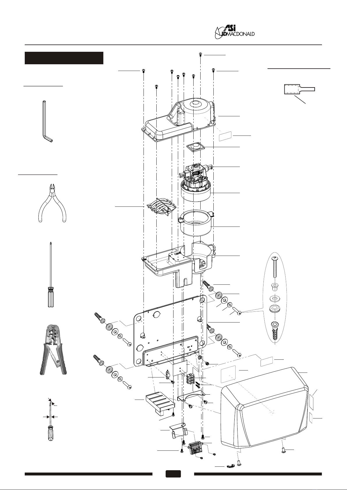
Operating Instructions and Parts Manual
Hand Dryer Surface-mounted ADA-compliant hand dr yer
General safety information:
Disconnect power at the
service breaker before installing or servicing.
This product is intended
for installation by a qualified service person.
Use AWG NO. 12 solid conductor for wiring.
All units must be supplied
with a 3-wire service. The ground wire must
be connected to the dryer's backplate.
Failure to properly ground
unit could result in severe electrical shock
and/or death.
www.asijdmacdonald.com.au
www.asijdmacdonald.com.au
1800 023 441
ASI JD MacDonald Pty .Ltd .