ASI JD MACDONALD Turbo-Tuff 10-0135-2 Service manual

1
PLEASE CAREFULLY READ THROUGH THIS MANUAL BEFORE USING THE PRODUCT.
OBSERVING ALL SAFETY INFORMATION, WARNINGS AND CAUTIONS WILL PROTECT
YOURSELF AND OTHERS. PLEASE KEEP INSTRUCTIONS FOR FUTURE REFERENCE.
Turbo-Tuff
Operating Instructions and Parts Manual
Hand Dryer Recessed High-Speed ADA-compliant hand dryer
TECHNICAL SPECIFICATIONS
ASI JD MACDONALD PTY. LTD.
www.asijdmacdonald.com.au 1800 023 441
www.asijdmacdonald.com.au
REF
TM
Rough Wall Opening 313mm W x 386mm H x 98mm D ] [12-5/16" x 15-3/16" x 3-7/8"
MODEL # 10-0135-2
ITEM CATEGORY
Operating Voltage , 0135-2
Output Warm Air Volume
Output Warm Air Temp
Output Air Speed
Motor Type
Motor Thermal Protection
Heater Element
Heater Thermal Protection
Drying Time
Standby Power
Circuit Operation
Sensor Range
Timing Protection
Timing Duration
Cover Type
Cover Finish
Net Weight
Shipping Weight
Unit Size
PERFORMANCE DATA
220-240VAC, 50/60Hz, 4.2A, 1.0KW
55°C when ambient Temp = 25°C. MAX adjustable by owner
MIN 69.2dB-A to 69.3dB-A MAX @ 2m, adjustable by owner
IP24
500W, 22000-29000rpm, adjustable, brush type, dual ball bearings
Auto resetting thermostat turns unit off at 95°C
Range adjustable by owner, 275-500 W
Auto resetting thermostat turns heater element off at 85°C,
resets at 75°C, thermal cut-off at 142°C
Less than 15 seconds
Less than 0.5W
Infrared automatic, self adjusting
100mm to 230mm, adjustable; standard 170mm ± 20mm
60 seconds auto shut off
1 second delayed turn off after last sensor read
18gauge [.047", 1.2mm thick drawn steel or 304 series stainless steel]
Satin on stainless steel
6.6kg
8.2kg
320mm W x 400mm H x 103mm D [12-19/32" x 15-3/4" x 4-1/16"]
Sound Level
Drip Proof
71-105m³/h [42-62CFM], adjustable by owner
124mph (182ft/s) [55.4m/s {199km/h}] - 184mph (270ft/s) [82.2m/s {296km/h}], adjustable by owner
93
(3-21/32″)
303
(11-59/64″) 103
(4-1/16″)
10(25/64″)
376
(14-51/64″)
DIM’S
mm(inch)
254
(10″)
400
(15-3/4″)
165
(6-1/2″)
320
(12-19/32″)

2
Operating Instructions and Parts Manual
Hand Dryer
Motor Heater TotalModelInput
Recessed High-Speed ADA-compliant hand dryer
Installation
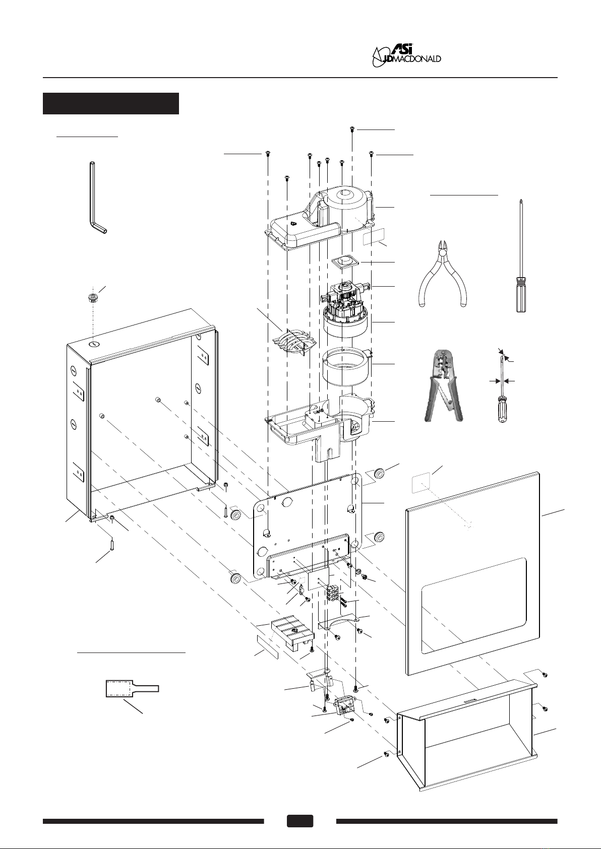
2. Remove front panel using security wrench included in kit and retain security screws. Place cover aside with
care to protect face finish until required in step 8.
3. Remove hand drying chamber using #2 PhilIips screwdriver and retain screws. Place chamber aside with
care to protect inside finish until required in step 7.
4. Remove two (2) mounting screws from bottom edge of chassis plate using #2 PhilIips screwdriver and retain
screws. Grasp motor securely and lift entire chassis slightly up & over retainer hooks welded to housing
top. Place chassis aside with care to protect unit until required in step 5.
5. Install supplied plastic KO bushing (or other, not supplied) into KO to be used for cable prior to installation
of cable into KO or box into RWO (Rough Wall Opening, previously prepared by others). Install wall box
housing into RWO locating stub cable into any one (1) of five (5) available KO locations on sides or top
of box. Using screws supplied with unit (or other types suitable to wall conditions, by others) tighten screws
through adjustable mounting tabs into framing in side walls of RWO to center wall box in opening.
6. Grasp chassis & motor assembly retained in step 3 and slightly lift to place over retainer hooks on housing
top to hold unit in place while driving screws. Using #2 PhilIips screwdriver tighten two (2) screws also
retained in step 3 through holes in bottom edge of chassis plate into threaded posts on wall box back.
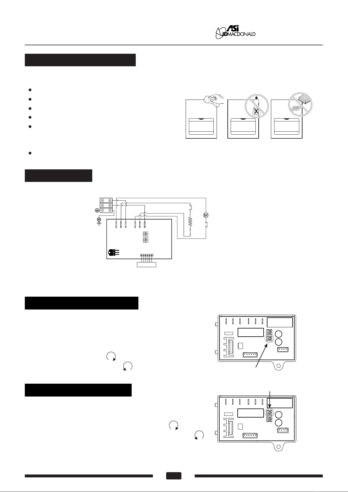
7. Refer to Circuit Diagram on page 4 of this Owner's Manual to match correct wire to terminal block on motor
chassis. Pull stub cable through bushing (previously installed, step 4) to allow clearance around hand drying
chamber (to be installed next) and enough length to prep ends for terminal block insertion after routing through
strain relief clamp on chassis. Clamp cable, prep ends of wires and insert correct wires into terminal block
at locations L, N & G. Using a small flat blade screwdriver ensure each wire is properly secured with terminal
block top lock screws.
Connections: (see fig. 6 & refer to Circuit Diagram and see Note B)
A. Connect the live wire (colored Brown, Red or Black) to the terminal block marked "L".
B. Connect the neutral wire (colored Black, Blue, White or Grey) or connect the second live wire (colored
Red or Orange) to the terminal block marked "N".
C. Connect the ground wire to the terminal block marked " " or to the green screw marked " ". Bare
grounding (earth) wires should be sleeved with green and yellow or green tubing.
Colors of live and neutral wires depend on voltage of supply service and requirements of Building and
Electrical Code having jurisdiction.
8. Reinstall hand drying chamber retained in step 2 into wall box housing using #2 PhilIips screw driver and
screws also retained in step 2 while being careful to not pinch cable arranged to route clear around hand
chamber in step 6.
9. Fasten the front panel onto the chassis box using the two (2) security screws retained in step 1 above
using the security wrench. Retain wrench for any possible service access during dryer lifetime. Turn ON
breaker at service panel (by others) and test dryer operation.
10. Record the unit S/N on the Registration Card and give this Owner’s Manual, the Installation Guide, Registration
Post Card and the security wrench to Owner or Facility Manager.
www.asijdmacdonald.com.au
1800 023 441
ASI JD M a c D o n a l d Pty . L t d .
1. Make sure power supply breaker is switched off. Installation must be carried out in accordance with the
current edition of the local wiring regulations code having jurisdiction. Installation should be performed
only by a qualified electrician.
VAC
220
230
240
Vac
220
230
240
Inrush A(W)
2.86 (630)
2.99 (689)
3.13 (750)
Operating A(W)
1.91 (420)
2.00 (459)
2.08 (500)
1.91 (420)
2.00 (459)
2.08 (500)
Vac
220
230
240
Inrush A(W)
4.77 (1050)
4.99 (1148)
5.21 (1250)
Operating A(W)
3.82 (840)
3.99 (918)
4.17 (1000)
№
0135-2
0135-2
0135-2
Operating A(W)

Operating Instructions and Parts Manual
Hand Dryer Recessed High-Speed ADA-compliant hand dryer www.asijdmacdonald.com.au
1800 023 441
ASI JD M a c D o n a l d Pty . L t d .
3www.asijdmacdonald.com.au
1.
2.
3.
Bushing Wall
8.
RWO
STUB
CABLE
DETAIL OF BUSHING IN
STEP 4 TO PUSH INTO KO
AB
A
4.
A
REMOVE
KO PUSH
BUSHING
INTO HOLE
B
CWIRE
GOES IN
D
5.
7.
A
B
A
B
B
AA
DETAIL `A´
FOR STEP 5
3/16"
(5)
Item # 36
NOTE B
OPTIONAL
TERMINALS
FOR STRANDED
WIRE 14-16 GA
FOR STEP 6
HOOK, TYP
A
B
6.
SEE CIRCUIT
DIAGRAM IN OWNER
MANUAL 1207311534
SLACK
CABLE
SEE
NOTE
B

Operating Instructions and Parts Manual
Hand Dryer Recessed High-Speed ADA-compliant hand dryer
4www.asijdmacdonald.com.au
www.asijdmacdonald.com.au
1800 023 441
ASI JD M a c D o n a l d Pty . L t d .
General safety information
Disconnect power at the
service breaker before installing or servicing.
This product is intended
for installation by a qualified service person.
Use AWG NO. 12 solid conductor for wiring.
All units must be supplied
with a 3-wire service. The ground wire must
be connected to the dryer's backplate.
Failure to properly ground
unit could result in severe electrical shock
and/or death.
Installation Kit Included (find in carton)
1. Wall box Installation Screws (M5x25 Philips pan head self threading) x 4 pcs
2. Nylon bushing x 1 pc
3. Crimp-on terminal wire tip x 3 pcs
Service Tool Included (with installation kit)
Security hex 4 mm x 1 pc (5/32" pin-hex will work if tool is lost)wrench
Please unpack the unit and check the quantity of the above tool and kit.
Operation
See Installation Guide (IG) on pages 2 & 3
Shake excess water from hands.
Place hands under the nozzle and dryer automatically starts operation. LED in sensor array shines
blue light during operation to guide user to optimal hand placement for fastest drying time.
Rub hands lightly and rapidly under the nozzle.
Dryer stops when hands are removed from
sensor zone or if maximum time is reached.
Sensor Adjustment Control.
See sensor range adjustment section on page 5
DO NOT OVER TURN!
Recommended mounting heights - from top edge of hand chamber above finished floor (AFF)
(50")
Men
Women
Children 4-7 years
Children 8-10 years
Children 11-13 years
Children 14-16 years
Handicaped
1270 mm
(47") 1194 mm
(35") 889 mm
(39") 991 mm
(43") 1092 mm
(47") 1194 mm
(40") 1016 mm

Operating Instructions and Parts Manual
Hand Dryer Recessed High-Speed ADA-compliant hand dryer www.asijdmacdonald.com.au
1800 023 441
ASI JD M a c D o n a l d Pty . L t d .
Periodic cleaning of the unit is recommended to ensure optimum performance.
Disconnect the electrical supply.
Remove the two cover-mounting screws.
Remove the cover.
Clean all dust lint from the interior of the dryer.
Wipe the cover with a damp cloth and mild
cleaning solution. Do not Soak. Never use
abrasives to clean the cover.
Replace the cover. Do not over tighten the screws.
Cleaning and Maintenance
Circuit Diagram
Circuit Board Module
MO2 HE2 NMO1 HE1L
Transistor
Power Switch
VR
G
N
L
Thermostat
Red(110-120V)
Black
G/Y
Blue
Motor With Ther mal Switch 2A
Heater With Thermo-fuse
FOR SENSOR
White(110-120V)
Sensor module
VR FOR SPEED
Black
Brown
5www.asijdmacdonald.com.au
VR.FOR AIR SPEED
Warm a r speed adjustmenti
1.Switch off the power, loosen the cover screws and
remove the cover.
2.Use small Philips head screwdriver or plastic flat blade
probe to turn VR shaft. Clock-wise [CW] to increase
power to maximum (+) , turn tool gently [CCW] to
reduce power as required(-) .
Sensor range adjustment
1.The range is 4" to 9" [100 mm to 230 mm],
standard setting is 7" [170 mm ± 20 mm].
2. .Clockwise: Increases the sensing range(+)
3.Counterclockwise: Decreases the sensing range(-) .
4.DO NOT OVERTURN!
VR.FOR SENSOR
Supply:220-240VAC, 50/60Hz

6
Operating Instructions and Parts Manual
Hand Dryer
Diagnostics and Remedies
If the dryer will not run
The dryer cycles by itself
or runs constantly
The dryer runs but air
stream is low pressure
and/or low velocity
Ensure that there is no obstruction on or in front of the IR sensor. Clean
any dirt or debris off the sensor lens. If problem persists, replace sensor.
First ensure that the breaker supplying the dryer is operational. If it is,
disconnect the power and remove the dryer cover. Taking suitable
precautions to avoid shock hazard, reconnect the power and check for
voltage at the terminal block. Verify that connections are made correctly.
Ensure that the supply voltage is correct. Dryer will run weakly if the
input voltage is too low. Verify voltage requirement on unit rating label
and correct supply as required.
The dryer makes a loud
noise and does not run
for a complete cycle
Ensure that the supply voltage is correct. Dryer will make a loud humming
noise if the input voltage is too high. Verify voltage requirement on unit
rating label and correct supply as required. If CBM has been damaged,
replace CBM, IR sensor module.
Symptom Corrective Actions for Initial Installation Failures
Recessed High-Speed ADA-compliant hand dryer
www.asijdmacdonald.com.au
1800 023 441
ASI JD M a c D o n a l d Pty . L t d .
Symptom Corrective Actions for In-Service Failures
If the dryer will not run
The IR sensor only "sees"
close range objects
Ensure that there is no obstruction on or in front of the IR sensor. Clean
any dirt or debris off the sensor lens. Check VR for sensor range setting. If
problem persists, disconnect the power and remove the dryer cover and
replace CBM, IR sensor module.
First ensure that the breaker supplying the dryer is operational. If it is,
disconnect the power and remove the dryer cover. Replace the CBM
and IR sensor module or disconnect heater element from circuit;check
resistance (Ω) of element with multimeter. If Ω is off-scale infinitely
large then replace element. If Ω is between 25 and 30 then check
motor brushes for wear and replace them if remaining graphite is
≤ 25/64" [10mm]. If after reassembly and testing there is stil no motor
function then replace motor. Taking suitable precautions to avoid
shock hazard, reconnect the power and check for Voltage at the
terminal block.
The air stream is low
pressure and velocity
Check the output nozzle for obstructions. If none are present, disconnect
the power. Remove the dryer cover. Remove any dust/lint buildup from
intake vent slots. Check VR for speed setting. Disassemble the blower-
motor/fan housing. Check the motor brushes for worn condition (≤ 25/64"
[10 mm] graphite remains) and replace them, if necessary.

7
Repair parts list
Operating Instructions and Parts Manual
Hand Dryer Recessed High-Speed ADA-compliant hand dryer
1
2
3
4
5
6
7
8
9
10
11
12
13
14
15
16
17
18
19
Key Part #
A0245
A0168
A0246
A0247
A0249
A0251
A0252
A0001
A0253
A0011
A0133
A0183
A0010
A0254
A0430
A0258
A0512
A0433
A0392
Description Qty
1
1
2
1
1
1
1
4
1
1
1
1
1
1
1
1
1
1
1
Blower housing - Upper
Motor rubber - Upper
Motor brushes
Motor
500W@120Vac
Heater assembly
500W@120Vac,28.8Ω
Motor rubber - Lower
Blower housing - Lower
Rubber grommet -Base
Base plate
Grounding screw with cup washer
Mylar shield with LNG marked
Nylon cable clamp
Terminal block
Blower mounting bracket
Circuit Board Module (CBM)
220-240Vac
Sensor bracket
Sensor module
Label, Circuit Diagram
Cover, Stainless steel - Satin
20
21
22
23
24
25
26
27
28
29
30
31
32
33
36
37
38
39
40
Key Part #
A0393
A0274
A0363
A0364
-
-
-
-
-
-
-
A0124
A0276
A0268
A0242
A0277
-
-
-
Description Qty
1
1
2
1
2
8
2
1
4
2
1
1
1
1
3
1
2
4
2
Rating label
10-0135-2
Dry hand chamber
Security hex screw
Recessed box
Screw M4x10, philips pan head
Self threading screw M4x10,
philips pan head
Screw M3x16,philips pan head
Screw M4x10,philips pan head
with external tooth lock washer
Screw M5x8,philips pan head
with external tooth lock washer
Screw M5x10,philips pan head
Wires Harness (Not Shown)
Security hex wrench
CBM terminal legend label
Caution Branch Circuit label
8.0A- 240Vac
Crimp-on wire tips for terminal block
Bushing, Nylon blk, KO
Screw M3x8,philips pan head
Screw M4x8,philips pan head
Hex nut,M4
www.asijdmacdonald.com.au
1800 023 441
ASI JD M a c D o n a l d Pty . L t d .

6
Operating Instructions and Parts Manual
Hand Dryer
8
Recessed High-Speed ADA-compliant hand dryer
www.asijdmacdonald.com.au
1800 023 441
ASI JD M a c D o n a l d Pty . L t d .
Assembly Diagram
Tool Req’d
Security hex wrench
Item 31
Tools Req’d
(Not provided)
Crimp tool
Philips #1/ #2
Wire cutter
Flat blade
3/64" THK(1.1)
36
Optional Terminals
(Provided in kit)
Use AWG 16-14(MAX)
1
2
5
8
9
10
11
13
12 14
15
16
17
18
19
21
22
24
23
24
25
25
25
26
27
28
29
20
28
37
SEE INSTALLATION STEPS
Typical Location
1 of 5 Positions
(Provided in kit)
(Provided in kit)
38
39
3
4
6
7
32
33
40
1/8" DIA(Ø3)
Table of contents
Other ASI JD MACDONALD Dryer manuals