4
Operating Instructions and Parts Manual
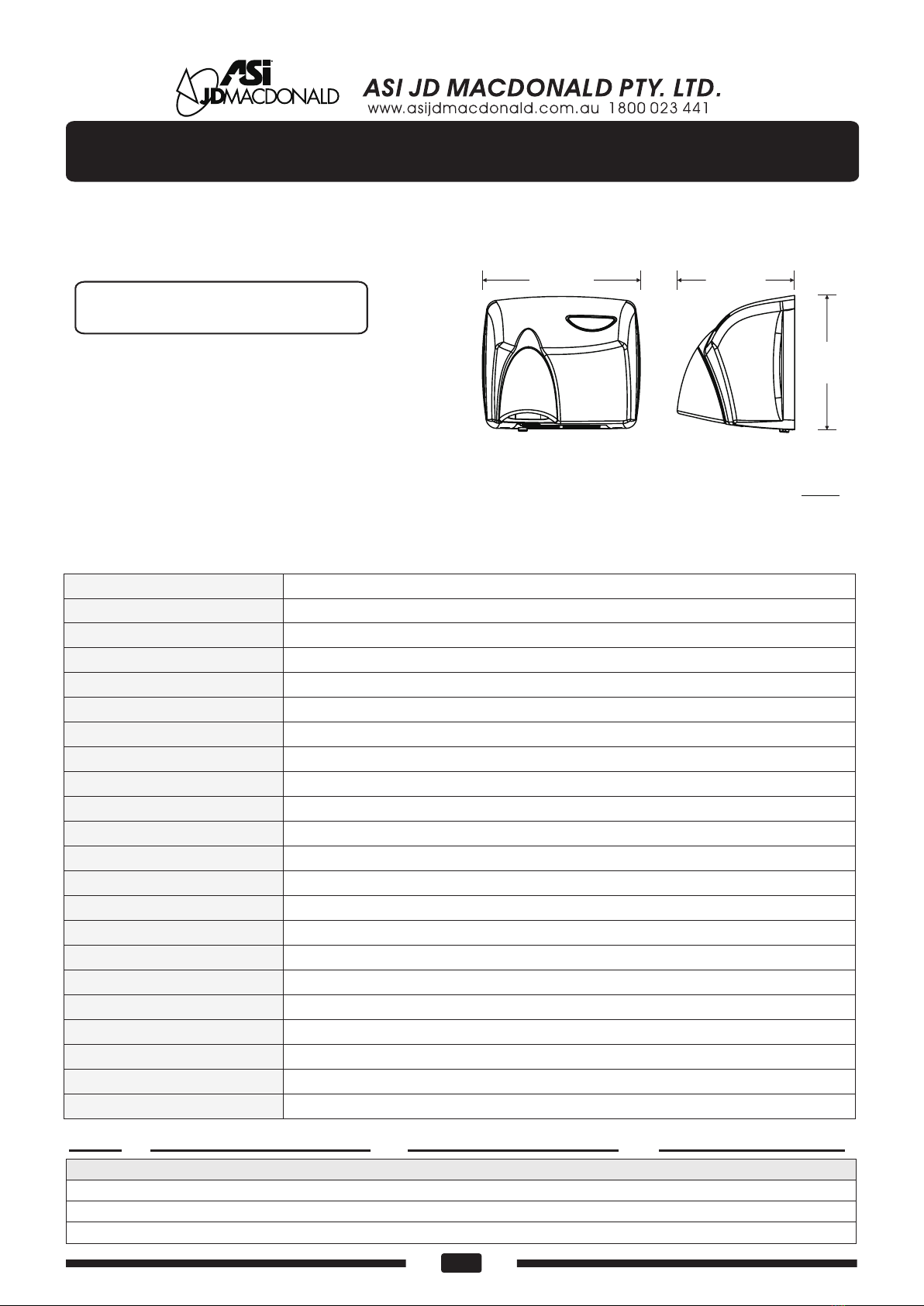
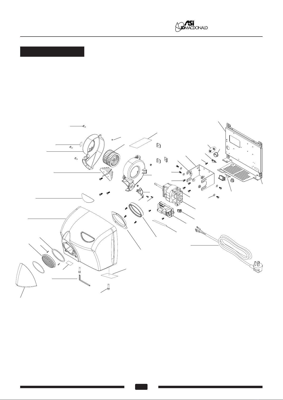
Hand Dryer
Symptom Corrective Action
Troubleshooting
If the dryer will not run First ensure that the breaker supplying the dryer is operational.
If it is, disconnect the power and remove the dryer cover.
Check for obstructions blocking the rotation of the blower and
clear any found. If it spins freely, check the motor and
thermostat for proper operation out of the unit. Replace any
failed items. Taking suitable precautions to avoid shock hazard,
reconnect the power and check for voltage at the terminal
block. If there is power and the dryer will not run, replace the
timer assembly and/or sensor module.
If the dryer cycles by itself, or runs
all the time, or shuts off by itself
while in mid-cycle
If the element gets hot but the fan
motor does not turn
Disconnect the power. Remove the dryer cover and check for
obstructions in the fan housing. Damaged fans must be
replaced. If there are no obstructions, replace the motor.
If the fan motor runs but the element
does not get hot (Dryer blows cold air)
Disconnect the power and remove the dryer cover. Check for
loose or damaged wires. Remove the blower housing.
Check the element for signs of burning or breakage. Damaged
element must be replaced. If the element does not appear
damaged, disconnect it at the timer assembly and check
element wire continuity (see tech spec). An open circuit
indicates damage to the element wire and to the integral
temperature limit control (TLC). Separate the TLC and test for
open circuit. If this is the case, replace the element and/or the
thermostat.
If the motor makes ticking/winding
noise when it runs
If the unit runs but makes a
buzz noise
Disconnect the power. Remove the dryer cover and check the
fan for obstructions and/or rubbing on the housing as it
rotates. Remove any obstructions and replace fan if the
rubbing condition exists.
Ensure that there is no obstruction on or in front of the
infrared sensor. Clean any dirt off the sensor lens. Check for
voltage spikes on power line. If the problem persists, replace
the timer assembly and/or the sensor module.
Disconnect the power. Remove the dryer cover and check the
brushes for worn condition (less than 25/64" (10mm) graphite
remains) and replace them, if necessary. Purchase rebuild
kit to perform repair.
Surface-mounted Automatic hand dryer www.asijdmacdonald.com.au
1800 023 441
www.asijdmacdonald.com.au
ASI J D MacD onal d Pty. Ltd.