ASI JD MACDONALD 10-20200-2 Service manual

1
PLEASE CAREFULLY READ THROUGH THIS MANUAL BEFORE USING THE PRODUCT.
OBSERVING ALL SAFETY INFORMATION, WARNINGS AND CAUTIONS WILL PROTECT
YOURSELF AND OTHERS. PLEASE KEEP INSTRUCTIONS FOR FUTURE REFERENCE.
Operating Instructions and Parts Manual
Hand Dryer Surface-mounted High-Speed hand dryer
MODEL # 10-20200-2
ITEM CATEGORY
Operating Voltage
Motor Thermal Protection
Heater Element
Heater Thermal Protection
Drying Time
Standby Power
LED Color
Circuit Operation
Sensor Range
Timing Protection
Timing Duration
Cover Type
Net Weight
Shipping Weight
Unit Size
PERFORMANCE DATA
220-240VAC, 50/60Hz, 6.25A, 1.5KW
93-136m³/h [55-80CFM], adjustable by owner
60°C when ambient Temp = 25°C. MAX adjustable by owner
144mph (212ft/s) [64.5m/s {234km/h}] - 213.4mph (313ft/s) [95.4m/s {343km/h}], adjustable by Owner
700W, 14000-18000rpm, adjustable, brush Type, dual ball bearings
Patented
MODEL # 10-20201-2
Sound Level
Drip Proof
Output Warm Air Volume
Output Warm Air Temp
Output Air Speed
Motor Type
Auto resetting thermostat turns unit off at 135°C
ON/ OFF Heating options; range adjustable by owner, 400-800W
Auto resetting thermostat turns heater element off at 85°C,
resets at 75°C, thermal cut-off at 142°C
Less than 12 seconds
Less than 0.5W
Standby colour: red; Active colour: blue
Infrared automatic, self adjusting
100mm to 170mm, adjustable; standard 150mm ± 20mm
60 seconds auto shut off
1 second delayed turn off after last sensor read
MIN 63.3dB-A to 69.2dB-A MAX @ 2m, adjustable by owner
IP21
3.0mm [1/8"] thick molded ABS plastic
10.8kg
12.8kg
322mm W x 588mm H x 197mm D [12-43/64" x 23-1/8" x 7-3/4"]
www.asijdmacdonald.com.au
ASI JD MACDONALD PTY. LTD.
www.asijdmacdonald.com.au 1800 023 441
TECHNICAL SPECIFICATIONS
DIM’S
mm(inch)
588
(23-1/8")
322
(12-43/64")
197
(7-3/4")

2
Operating Instructions and Parts Manual
Hand Dryer Surface-mounted High-Speed hand dryer
Recommended Mounting Heights Above Finished Floor (AFF)
Socket Location
The dryer is supplied with a power cord. The power cord
entry position is in the rear, right side bottom of dryer. The
length of the power cord is 39-3/8 (1M). The power cord
"
can reach to the right side within the distance of 21-21/32"
(550) and reach to the left side within the distance of
17-23/32 (450). Alternatively the unit may be hard wired
"
to a terminal block through a rear panel KO.
See Mounting Template on Installation Guide 1203270822
VAC
220
230
240
Motor Heater
Vac
220
230
240
Inrush A(W)
4.00 (882)
4.19 (964)
4.38 (1050)
Operating A(W)
2.67 (588)
2.79 (643)
2.92 (700)
3.05 (672)
3.19 (735)
3.33 (800)
Vac
220
230
240
Total
Inrush A(W)
7.05 (1554)
7.38 (1699)
7.71 (1850)
Operating A(W)
5.72 (1260)
5.98 (1378)
6.25 (1500)
№
20200(1)-2
20200(1)-2
20200(1)-2
ModelInput
Operating A(W)
Detail A Unit Rear
1-29/64"
(37)
Ø7/8 (Ø22)
ELEC.K.O
Datum point
2-17/64"
(57.5)
Outline
of
Mounting
Wall Plate
Outline of
Housing
www.asijdmacdonald.com.au
1800 023 441
ASI JD MacDonald Pty. Ltd.
A
BC
Top of Hand
Drying Chamber
Datum Point
Bottom of
Dryer
Floor
17-23/32"
(450) 21-21/32"
(550)
Floor
Power Cord Reach Range (PCRR)
Patented
45-9/32"
42-33/64 "
30-45/64 "
34-41/64"
37-63/64 "
42-33/64"
(1150)
(1080)
(780)
(880)
(965)
(1080)
(710)
(640)
(340)
(440)
(525)
(640)
27-61/64"
25-13/64 "
13-25/64 "
17-21/64"
20-43/64 "
25-13/64"
(622)
(552)
(252)
(352)
(437)
(552)
24-31/64"
21-47/64 "
9-59/64"
13-55/64"
17-13/64 "
21-47/64"
A
Men
Women
Children 4-7 years
Children 8-10 years
Children 11-13 years
Children 14-16 years
From Top of Hand
Drying Chamber
B
From Datum Point
C
From Bottom of Dryer
DIM’S
inch(mm)

3
Operating Instructions and Parts Manual
Hand Dryer Surface-mounted High-Speed hand dryer
Installation
1. Make sure power supply breaker is switched off. Installation must be carried out in accordance with
the current edition of the local wiring regulations code having jurisdiction. Installation requiring hard
wiring should be performed only by a qualified electrician.
2. Place template against wall at desired height (see mounting height recommendations) and mark
locations of eight (8) mounting holes and wire service entry at knockout (KO) location.
Note: For two or more dryers, dryers should be no closer than 24 inches (610 mm) on center.
3. Use L-Key (supplied) to unlock security hex socket screw and withdraw filter access drawer.
4. a. Drill eight (8) holes at locations marked of Ø9/32" (Ø7) x 1-3/8" (35) deep if using wall anchors
supplied with unit (fig.1)
b. Remove template and Insert eight (8) plastic anchors (supplied) into drilled holes (fig. 2).
Install supplied anchors flush with wall face, or install other fastening system suitable for wall
conditions (not supplied).
nserting eight (8) screws (supplied) to fix backplate into plastic c. Attach base plate to wall by i
anchors (fig. 3). For wood wall/studs use Ø1/4 inch (M6) screws at length that will ensure 1
inch (25) min. stud penetration. For masonry walls use expansion bolts or anchors for Ø1/4
inch (M6) screws to ensure penetration 1/4 inch (6) deeper than anchor. Shim if necessary to
ensure base plate is flat against wall.
5. a. Hang the dryer on the base plate (fig. 4).
b. For in-wall (concealed) power supply -
Provide supply wire to KO location according to local code and attach securely to chassis at KO
with strain relief connector (supplied).
c. For Surface Mounted Conduit (exposed) power supply or using power cord (supplied) -
Provide appropriate conduit to entry location according to local code and attach securely to
chassis with correct strain relief connector (not supplied) or install unit on wall within PCRR to
duplex outlet.
d. Install locking screw (supplied) into wall plate through the hole at backplate center bottom. (fig. 5)
6. a. Connect hard wired power provided at KO location to terminal block behind cover panel (RH-bottom)
behind filter drawer. Turn on circuit breaker to initiate ‘stand by- ready to operate’ status.
A. Connect the live wire (colored Brown, Red or Black) to the terminal block marked "L".
B. Connect the neutral wire (colored Black, Blue, White or Grey) or connect the second live wire
(colored Red or Orange) to the terminal block marked "N".
C. Connect the ground wire to the terminal block marked " " . Bare grounding (earth) wires should
be sleeved with green and yellow or green tubing. Colors of live and neutral wires depend on
voltage of supply service and requirements of Building and Electrical Code having jurisdiction.
b
. Connect power cord to initiate ‘stand by- ready to operate’ status.
7. Replace the filter access drawer, being careful to not over-tighten the security screw.
8. See separate sections for owner options on heater operation and air speed adjustment.
See Installation Guide 1203270822
Connections:
www.asijdmacdonald.com.au
1800 023 441
(fig. 1) (fig. 2) (fig. 3)
(fig. 4) (fig. 5)
S
VIEW S
SECURITY
SCREW
ASI JD MacDonald Pty. Ltd.

4
Operating Instructions and Parts Manual
Hand Dryer Surface-mounted High-Speed hand dryer
Put your hands into the opening.
Rub hands together to speed dry.
Remove hands and dryer will stop
automatically.
Dryer maintains operation for 1 second
after last sensor activation to evaporate
droplets.
1.
2.
3.
Circuit Diagram
Cleaning and Maintenance
Wipe the cover with a damp cloth and mild cleaning solution.
Do not Soak, Do not hose down.
Never use abrasives to clean the cover. Caustic chemicals may damage unit finish.
No internal parts need any regular cleaning.
Periodic cleaning of the unit is recommended to ensure optimum performance.
4.
Operation
General safety information
Disconnect power at the
service breaker before installing or servicing.
This product is intended
for installation by a qualified service person.
Select wire ga to suit unit model ratings.
All units must be supplied
with a 3-wire service. The ground wire must
be connected to the dryer's ground terminal.
Failure to properly ground
unit could result in severe electrical shock
and/or death.
Installation Kit Included (find in carton)
1. Self-Threading pan head screws №10 x 1-1/4" (M5 x 32) x 8 pcs
2. Plastic expansion anchor Ø9/32" x 1-3/8" (Ø7 x 35) x 8 pcs
Service Tools Included (with installation kit)
Security hex 4 mm x 1 pc (5/32" pin-hex will work if tool is lost)wrench
Deep C-socket Wrench (for Cord Strain Relief Nut)
Patented See Separate Sections for Filter,
Ceramic Water Evaporator and
Drain Tray Maintenance
Please unpack the unit and check the quantity
of the tools and kit.
www.asijdmacdonald.com.au
Patented
www.asijdmacdonald.com.au
1800 023 441
1. 2. 3.
Circuit Board Module
LED & SENSOR
MO2 HE2 NMO1 HE1L
Transistor
Power Switch
VR1
G
N
L Red(110-120VAC)
Black
Black
G/Y
Blue
Brown
Motor With Thermal Switch 2A
Heater With Thermo-fuse
1 2 3 4
FOR SENSOR
VR2 FOR MOTOR
White (110-120VAC)
Thermostat
Supply:220-240VAC, 50/60Hz
ASI JD MacDonald Pty. Ltd.

5
Operating Instructions and Parts Manual
Hand Dryer Surface-mounted High-Speed hand dryer
Air Speed Adjustment
Sound volume during operation may be modified by adjusting the motor speed. When lowering
the motor speed, the drying time will increase. The factory setting for dryer motor speed is high.
1. Use security hex wrench (supplied) to unlock and withdraw filter access drawer. (fig. 1).
2. Use small flat blade screwdriver, gently turn adjustment control shaft clock-wise [CW] to (fig. 2)
increase power to maximum (shaft will hard stop; DO NOT OVERTURN!). Turn tool gently
CCW to reduce power as required (shaft will hard stop; DO NOT OVERTURN!). Note that at
minimum power the unit may not start if low line Voltage condition exists.
3. Replace the filter access drawer and lock the security screw, being careful to not over tighten screw.
To adjust the dryer motor speed:
www.asijdmacdonald.com.au
1800 023 441
(fig. 1)
Speed
Adjustment
Control
Increase powerReduce power
Reduce
Patented
(fig. 2)
ASI JD MacDonald Pty. Ltd.

How to Change the SUPER Filter
1. Use security hex wrench (supplied) to unlock and withdraw the filter access drawer. (fig. 1).
2. Change the SUPER filter (fig. 2) by lifting up out of the drawer by lifting tabs. Dispose of the old
filter appropriately and replace with a new filter, HEPA side (white) up. See P/L for replacement P/N.
3. Replace the filter access drawer and lock the security screw, being careful to not over tighten screw.
SUPER Filter-
In general use (normal indoor washrooms), it's recommended to change the SUPER filter every
six (6) months.
In dusty environments (factories, outdoor washrooms), it's recommended to change it every three
(3) months.
6
Operating Instructions and Parts Manual
Hand Dryer Surface-mounted High-Speed hand dryer
Recommended Period for Changing the SUPER filter
SUPER filter Assembly Information
Instructions for use, maintenance and changing the absorbent ceramic
water evaporator
The absorbent ceramic can absorb 70g of water, and has the capacity to take a full load approximately
280 times per day. The ceramic also can evaporate water. During normal use, water will be evaporated
continuously and maintain the absorbent function.
Maintenance simply requires clearing its surface. Normally, its lifetime will be the same as the machine.
Improper use or maintenance could result in breakage; see below for replacement instructions.
LIFTING
TAB
(TYP)
HEPA Filter
(white corrugated)
Antibacterial
Filter
(green)
Carbon
Filter
(black)
Antibacterial
Filter
Carbon
Filter
HEPA Filter
MAKE SURE POWER IS OFF PRIOR TO STEP Fig. 2
SEE PAGE 9.
www.asijdmacdonald.com.au
1800 023 441
(fig. 2)
SUPER filter
(fig. 1)
Patented
Gasket
(Retain and
Reuse)
ASI JD MacDonald Pty. Ltd.

7
Operating Instructions and Parts Manual
Hand Dryer Surface-mounted High-Speed hand dryer
1. Use the to loosen the security screw and remove the filter access drawer. (fig. 1) security hex wrench
2. Use the to remove and retain the security screw from the base plate and remove the dryer. (fig. 2) security hex wrench
3. Use a Philips screwdriver to loosen the two (2) screws on the ceramic, and replace it with a new one,
making sure to use the washers and being careful to not over tighten the screws. (fig. 3)
4. Rehang the dryer back on the wall plate and secure the security screw into the base plate.
5. Reconnect in-wall power cord, if so equipped. Replace terminal cover.
6. Replace the filter drawer and lock the security screw, being careful to not over tighten the screw.
7. Restore power for operation.
Instructions for use of the drain tray
Generally, the remaining water following usage will evaporate from the absorbent ceramic plate. During
high usage frequency events excessive water will flow automatically to the drain tray. The capacity of the
drain tray is 8 oz (240 ml). It is recommended that the drain tray be cleaned every three (3) months
under heavy usage conditions and every four to six (4 ~ 6) months under light usage conditions in
indoor washrooms. The drain tray is retained on tracks molded into the bottom opening of the filter
access drawer. It is important that the wide end of the drain tray be inserted first and be positioned fully
at the back of the track. The bottom center recess is to be used as a finger grip handle to assist in
removing and reinstalling the drain tray. Water will flow through the overflow drain port if the drain tray
is full. A drain tube (not included) may be added as required by owner preference. The size of the drain
tubing (by others) is I.D. 15/64" (Ø6), O.D. 25/64" (Ø10), length is determined per installation to suit
conditions. See Fig. 1.
www.asijdmacdonald.com.au
1800 023 441
(fig. 1)
(fig. 2)
(fig. 3)
Patented
REUSE
SCREW
(TYP)
CONICAL WASHERS
(REUSE EXISTING)
(fig. 1)
Patented
DRAIN TRAY
HANDLE
DRAIN TUBE CUT TO
LENGTH TO SUIT
(BY OTHERS)
TRACKS
conditions. See Fig. 1.
ASI JD MacDonald Pty. Ltd.

8
Operating Instructions and Parts Manual
Hand Dryer Surface-mounted High-Speed hand dryer
If the dryer will not run
The dryer cycles by itself
or runs constantly
The dryer runs but air
stream is low pressure
and/or low velocity
Ensure that there is no obstruction on or in front of the IR sensor. Clean
any dirt or debris off the sensor lens. If problem persists, replace sensor.
If symptom continues after sensor replacement, then replace CBM.
First ensure that the breaker supplying the dryer is operational. If it is,
disconnect the power and remove the dryer cover. Taking suitable
precautions to avoid shock hazard, reconnect the power and check for
Voltage at the terminal block. Verify that connections are made correctly.
Adjust the VR-2 (on item 34) to make sure it is not set too low.
Ensure that the supply Voltage is correct. Dryer will run weakly if the
input Voltage is too low. Verify Voltage requirement on unit rating label
and correct supply as required.
The dryer makes a loud
noise and does not run
for a complete cycle
Ensure that the supply Voltage is correct. Dryer will make a loud humming
noise if the input Voltage is too high. Verify Voltage requirement on unit
rating label and correct supply as required. If CBM has been damaged,
replace CBM, IR sensor-LED module, VR-2/ SW-1 and CBM wire harnesses.
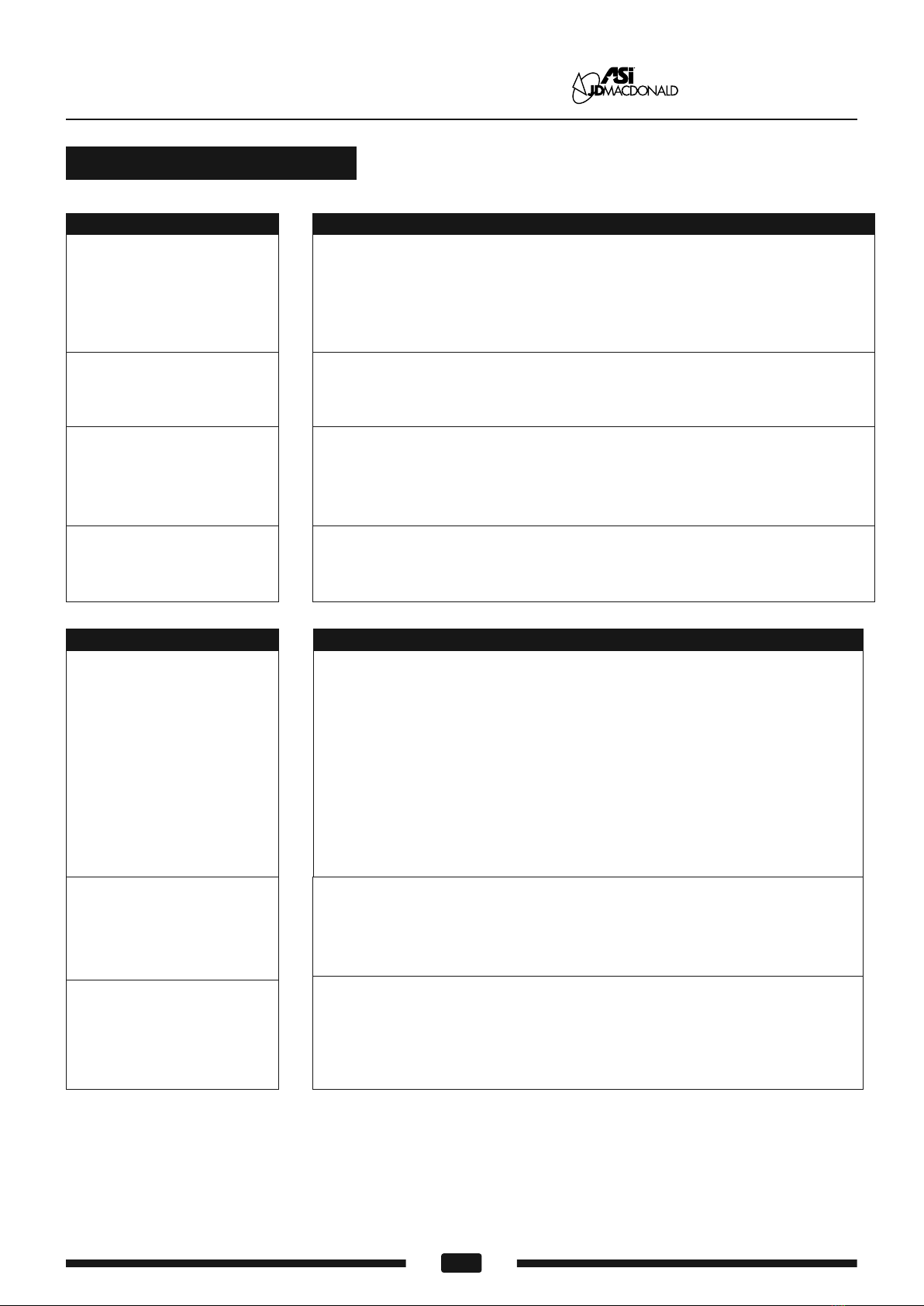
Symptom Corrective Actions for Initial Installation Failures
Diagnostics and Remedies
www.asijdmacdonald.com.au
1800 023 441
Symptom
If the dryer will not run
The IR sensor only "sees"
close range objects
The air stream is low
pressure and velocity
Corrective Actions for In-Service Failures
Ensure that there is no obstruction on or in front of the IR sensor. Clean
any dirt or debris off the sensor lens. Check VR for sensor range setting. If
problem persists, disconnect the power and remove the dryer cover and
replace CBM, IR sensor module.
First ensure that the breaker supplying the dryer is operational. If it is,
disconnect the power and remove the dryer cover. Replace the CBM
and IR sensor module or disconnect heater element from circuit;check
resistance (Ω) of element with multimeter. If Ω is off-scale infinitely
large then replace element. If Ω is between 15 and 20 then check
motor brushes for wear and replace them if remaining graphite is
≤ 25/64" [10mm]. If after reassembly and testing there is stil no motor
function then replace motor. Taking suitable precautions to avoid
shock hazard, reconnect the power and check for Voltage at the
terminal block.
Check the output nozzle for obstructions. If none are present, disconnect
the power. Remove the dryer cover. Remove any dust/lint buildup from
intake vent slots. Check VR for speed setting. Disassemble the blower-
motor/fan housing. Check the motor brushes for worn condition (≤ 25/64"
[10 mm] graphite remains) and replace them, if necessary.
ASI JD MacDonald Pty. Ltd.

9
Operating Instructions and Parts Manual
Hand Dryer Surface-mounted High-Speed hand dryer
Common First Disassembly Steps
First, Make sure power is OFF before starting step fig. 2. Second, Either unplug power cord or
disconnect in-wall power connections behind terminal cover (item 6) prior to starting step fig. 2.
www.asijdmacdonald.com.au
1800 023 441
Motor Replacement-
Brush Replacement-
(fig. 1)
(fig. 2)
(fig. 3)
(fig. 4)
(Item 12)
Start with steps fig’s 1-3
(Item 63)
(fig. 5)
Screw M4 x 12
Retain and Reuse
Item # 55 x 12
Screw M4 x 10
Retain and Reuse
Item # 49 x 1
Screw M4 x 12
Retain and Reuse
Item # 56 x 9
Heater assembly
Item # 14
Heater Replacement- (Item 14)
Start with steps fig’s 1-3. Remove blower housing
upper (Item 9) see step fig. 4 under motor replacement.
Start with steps fig’s 1-3. Remove blower housing
upper (Item 9) see step fig. 4 under motor replacement.
(fig. 5)
Screw 1/4" x 3/4"
Retain and Reuse
Item # 22 x 1
Screw M4 x 10
Retain and Reuse
Item # 50 x 4
Spade terminal
Brush
TYP 2
Item # 63
(fig. 5)
Motor rubber - Lower
Item # 11
Motor
Item # 12
ASI JD MacDonald Pty. Ltd.

10
Operating Instructions and Parts Manual
Hand Dryer Surface-mounted High-Speed hand dryer
www.asijdmacdonald.com.au
1800 023 441
CBM Replacement-
Speed Control - CBM Replacement-
(Item 26)
Start with steps fig’s 1-3
Terminal
Label
Item # 25
CBM
Item # 26
Screw M4 x 10
Retain and Reuse
Item # 51 x 2
(Item 34)
Start with steps fig’s 1-3
Screw M4 x 10
Retain and Reuse
Item # 49 x 1
VR2 Cover
Item # 32
Reduce
Speed control - CBM label
Item # 33
(fig. 4)
(fig. 4)
Speed control - CBM
Item # 34
Screw M3 x 10
Retain and Reuse
Item # 47 x 2
MO2
HE2
N
MO1
HE1
L
VR2
LED&SENSOR
Plug in Sockets
VR2
Plug in Sockets
ASI JD MacDonald Pty. Ltd.

11
Operating Instructions and Parts Manual
Hand Dryer Surface-mounted High-Speed hand dryer
www.asijdmacdonald.com.au
1800 023 441
Sensor Module Replacement-
Start with steps fig’s 1-3
(Item 19)
LED&SENSOR
Plug in Sockets
Sensor and LED module
Item # 19
Screw M3 x 10
Retain and Reuse
Item # 47 x 2
CBM
Item # 26
(fig. 4)
(fig. 5)
Nozzle Manifold Replacement-
Start with steps fig’s 1-3. Remove blower housing’ upper (Item 9)
see step fig. 4 under motor replacement.
(Item 16, 17)
N-Nozzle manifold - RH
Item # 16
N-Nozzle manifold - LH
Item # 17
CBM
Circuit Board Module
Sensor Adjustment Control
Clockwise: Lengthen the sensing range(+)
Counterclockwise: Shorten the sensing range(-)
DO NOT OVERTURN!
Sensor wire with noise filter/core
Item # 59
ASI JD MacDonald Pty. Ltd.

12
Operating Instructions and Parts Manual
Hand Dryer Surface-mounted High-Speed hand dryer
2-1/2"
(64)
Cable prep
L-Wrench
or
screwdriver
C-Wrench to loosen/
tighten (item 36)
Conversion from power cord (as supplied) to in-wall power supply (by others)-
See also installation guide 1203270822.
Start with steps fig’s 1-3. Make sure power is OFF before starting.
Remove power cord (item # 60) from terminal block and strain relief using C-socket wrench. Provide power
supply (by others) in appropriate voltage for model selected at location per diagram in detail A (pg 2 this
manual) and step 5.b. (pg 3 this manual). Feed power cord into cord-grip strain relief (item # 36) and follow
step 6.a. Connections A-C (pg 3 this manual). Insertion of 16AWG ~ 14AWG stranded wires into terminal
block (item # 35) receptacles will be easier and provide better results if crimp-on wire tips (item # 64) are
installed on wire ends prior to feeding cable through cord-grip (item # 36). If solid wire power cable is
provided, tips are not required.
1-29/64"
(37)
2-17/64
"
(57.5)
Wall
Power
Location
Housing
Datum
STUB
In-wall
Power cable
(by others)
3/16"
(5)
1
Crimp-on tip
Item # 64
Wire
(Stranded)
2
Outline
of
Mounting
Wall Plate
STUB
In-wall
Power cable
(by others)
www.asijdmacdonald.com.au
1800 023 441
Chamber Replacement-
(Item 18)
Start with steps fig’s 1-3. Remove blower housing’ upper (Item 9)
see step fig. 4 under motor replacement.
N-Chamber
Item # 18
Screw M3 x 10
Retain and Reuse
Item # 47 x 2
ASI JD MacDonald Pty. Ltd.

13
Operating Instructions and Parts Manual
Hand Dryer Surface-mounted High-Speed hand dryer
Repair parts list
1
2
3
4
5
6
7
8
9
10
11
12
13
14
15
16
17
18
19
20
21
22
23
24
25
26
27
28
29
30
31
32
33
34
Key Part #
A0194
A0278
A0195
A0132
A0196
A0197
A0417
A0199
A0200
A0201
A0202
A0147
A0362
A0419
A0205
A0307
A0308
A0309
A0310
A0210
A0211
A0212
A0011
A0213
A0320
A0420
A0218
A0219
A0220
A0221
A0222
A0223
A0422
A0423
Description Qty
1
1
1
1
1
1
1
1
1
1
1
1
1
1
1
1
1
1
1
1
1
1
2
1
1
1
1
1
1
1
1
1
1
1
1
Drawer assembly
Super filter
Filter rubber seal
CAUTION label
240Vac - 8A
LNG label
Terminal cover
240V Label, Circuit Diagram
Cover - front
Blower housing - Upper
Blower housing rubber seal
Motor rubber - Lower
Motor
700W@120Vac
Motor rubber cup ring
Heater assembly
800W@120Vac,18Ω
Blower housing - Lower
N-Nozzle manifold - RH
N-Nozzle manifold - LH
N-Chamber
N-Sensor and LED module
Bracket - RH
Bracket - LH
Security hex screw
Grounding screw with cup
Air intake screen
Terminal label
Circuit Board Module (CBM)
240Vac
Socket ID label
CBM bracket
Main bracket
Drain tray label
Drain tray
VR2 cover
Speed control - CBM label
Speed control - CBM
35
36
37
38
39
40
41
42
43
44
45
46
47
48
49
50
51
52
53
54
55
56
57
58
59
60
61
62
63
64
65
66
67
Key Part #
A0010
A0226
A0423
A0230
A0231
A0232
A0233
A0234
A0235
A0236
A0237
-
-
-
-
-
-
-
-
-
-
-
-
A0193
A0335
A0124
A0241
A0279
A0242
A0243
A0244
A0239
Description Qty
1
1
1
1
1
1
1
1
1
1
1
7
2
2
4
2
2
8
3
12
30
8
8
1
1
1
1
2
3
1
2
1
Terminal block
Cable holder
Rating label
20200-2 220-240VAC
20201-2 220-240VAC
Cover - rear
Base plate - cover side
Base plate - wall side
Αbsorbent ceramic
Foam gasket A (on Cover - rear)
Foam gasket B
(on Main bracket -RH)
Foam gasket C
(on Main bracket - Bottom)
Foam gasket D
(on Drain tray)
-
Self threading screw M3x10,philips pan head
Self threading screw M3x16,philips pan head
Self threading screw M4x10,philips pan head
Screw M4x10,philips pan head
with external tooth lock washer
Self threading screw M4x16,philips pan head
Self threading screw M5x10,philips pan head
Self threading screw M5x15,philips pan head
Screw M4x12,philips pan head
Self threading screw M4x12,philips pan head
Self threading screw №10x1-1/4",philips pan
head
Plastic expansion anchor
Ø9/32" x 1-3/8" (Ø7 x 35)
Wires Harness (Not Shown)
Power cord 220-240 Vac
Security hex wrench
C-Wrench
Motor brush
Crimp-on wire tips for terminal block
Instruction label
Conical washer
Sensor wire with noise filter/core
www.asijdmacdonald.com.au
1800 023 441
-
A0424
ASI JD MacDonald Pty. Ltd.

14
Operating Instructions and Parts Manual
Hand Dryer Surface-mounted High-Speed hand dryer
www.asijdmacdonald.com.au
1800 023 441
Assembly Diagram
1
2
34
8
9
10
11
12
13
14 15
16
17
18
19
20
21
24
26
28
29
30
32
33
34
35
37
36
40
39
41
25
27
7
5
6
31
38
23
22
42
43
44
45
55
52
53
57
48
49
58
51
56
22
47
54
56
49
Tools Req’d
(Provided in kit)
60
62
61
63
64
Optional Terminals
(Provided in kit)
Use AWG 16-14(MAX)
Tools Req’d
(Not provided)
Crimp tool
Philips #1/ #2
Wire Cutter
Flat blade
Ø3(1/8")
M1(3/64")
50
65
66
67
ASI JD MacDonald Pty. Ltd.
This manual suits for next models
1
Table of contents
Other ASI JD MACDONALD Dryer manuals
Popular Dryer manuals by other brands

Kuppersbusch
Kuppersbusch TD 1458.0W-CN user manual

Smeg
Smeg DT292PIT user manual

Bosch
Bosch WPG23100IN User manual and installation instructions

Laundrylux
Laundrylux Wascomat Encore DLHF0315CEMI installation manual

Ariston
Ariston ASL 65 VXS NA Use and installation manual

Parker Hiross
Parker Hiross Polestar-Smart Series user manual