9
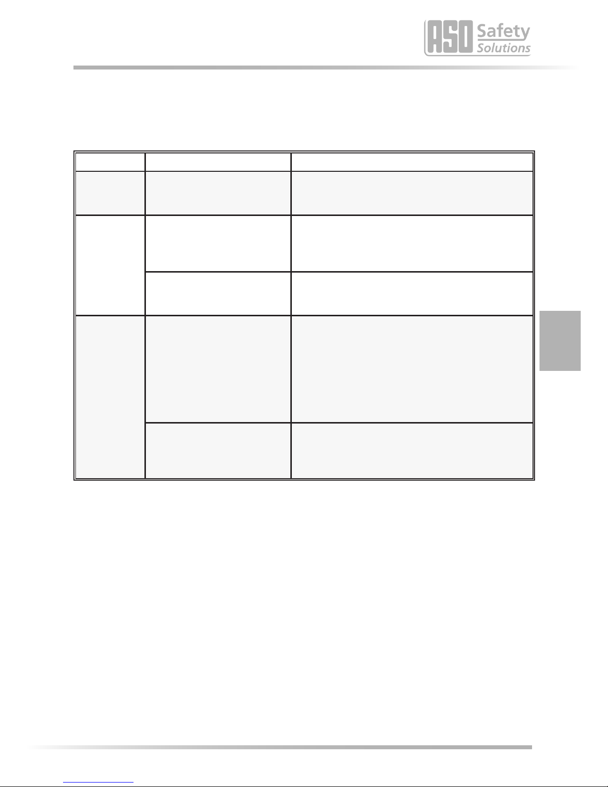
10. Fehlerdiagnose
Bei korrekter Verdrahtung und Anlegen der Versorgungsspannung darf nur die grüne LED leuchten. Bei
Aueuchten einer der roten LED‘s ist ein Fehler im System vorhanden, der sich mit Hilfe der LED eingrenzen
lässt.
LED Fehler Fehlerbeseigung
LED‘s
leuchten nicht
Versorgungsspannung fehlt,
zu gering
oder falsch angeschlossen
Anschlüsse und Versorgungsspannung überprüfen:
- 24 V AC/DC an Klemmen 8 9
Toleranzbereich: ±10%
einzelne rote
LED leuchtet
Sicherheitskontaktleiste(n)
nicht angeschlossen,
fehlerha angeschlossen
oder defekt
- Anschlüsse der entsprechenden Sicherheitskontakt-
leiste überprüfen (abgequetschte Zuleitungen,
brüchige Zuleitungen etc.)
- Sicherheitskontaktleiste(n) überprüfen*
Ein Sicherheitskontaktleisten-
Anschluss wird nicht benutzt
Nicht benutzte Sicherheitskontaktleisten-Anschlüsse
dauerha mit einem der mitgelieferten 8,2 kΩ-Wider-
stände überbrücken
beide roten
Transmit LED‘s
leuchten
Übertragungsstrecke ist gestört
oder fehlerha monert
- mech. Montageanleitung beachten (INDUS Sicher-
heitsübertragungsystem)
- Übertragungskerne auf Verschleiß überprüfen.
- Seilkreis überprüfen; hier ist darauf zu achten, dass
beide Übertragungskerne sich innerhalb des Seilkreis
benden
- Kontaktstellen Seil / Torkörper überprüfen.
- Versorgungsspannung überprüfen**
Sicherheitskontaktleiste(n)
nicht angeschlossen,
fehlerha angeschlossen
oder defekt
- Anschlüsse der entsprechenden Sicherheitskontakt-
leiste überprüfen (abgequetschte Zuleitungen,
brüchige Zuleitungen etc.)
- Sicherheitskontaktleiste(n) überprüfen*
* Liegt der Fehler nicht in der Verdrahtung, kann die Funkon der Elektronik durch Belegung aller Sicher-
heitskontaktleisten-Eingänge an der INDUS rail 71-242 (INDUS rail 71-942) Auswertelektronik (Klemmen
3, 10 und Klemmen 3, 11) und am miahrenden Spulenkern (Anschlüsse Ound C) mit jeweils einem
8,2 kΩ Widerstand überprü werden.
Arbeitet danach die Elektronik einwandfrei, müssen die Sicherheitskontaktleisten mit einem Wider-
standsmessgerät überprü werden. Hierfür muss die jeweilige Verbindung der Sicherheitskontaktleiste
zur Auswertelektronik oder zum miahrenden Spulenkern aufgetrennt und mit einem Widerstands-
messgerät verbunden werden.
Bei unbetägter Sicherheitskontaktleiste muss der Widerstand 8,2 kΩ ±500 Ω betragen. Ist die Sicher-
heitskontaktleiste betägt, darf der Widerstand 500 Ω nicht überschreiten.
** Sollten die beiden LED’s für die miahrenden Sicherheitskontaktleisten (Transmit Opening und Transmit
Closing) leuchten, ist ein Fehler im indukven Übertragungssystem vorhanden. Die häugsten Fehler-
quellen hierfür sind schlechte Verbindungen an den Spulenkernen, nicht ordnungsgemäß installierte
Seilsystemkomponenten (siehe Montageanleitung INDUS rail-Sicherheitsübertragungssystem) oder
eine unzulässig niedrige Versorgungsspannung.
Die Seilschleife darf einen maximalen Widerstandswert von 3 Ω haben. Der Widerstandswert kann durch
Lösen des Stahlseiles von der Erdungsklemme und anschließendem Messen zwischen Stahlseilende und
Erdungsklemme ermielt werden.
Deutsch
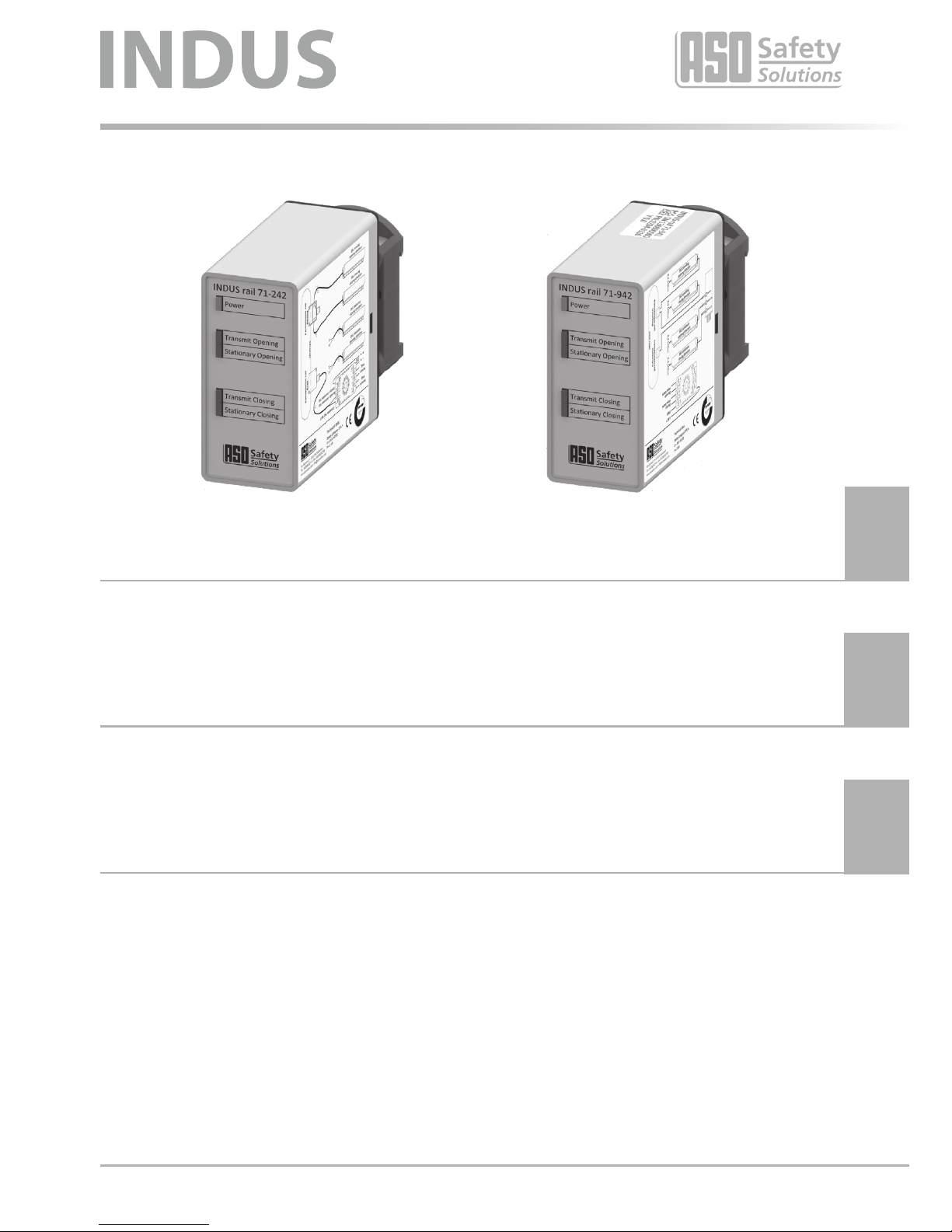
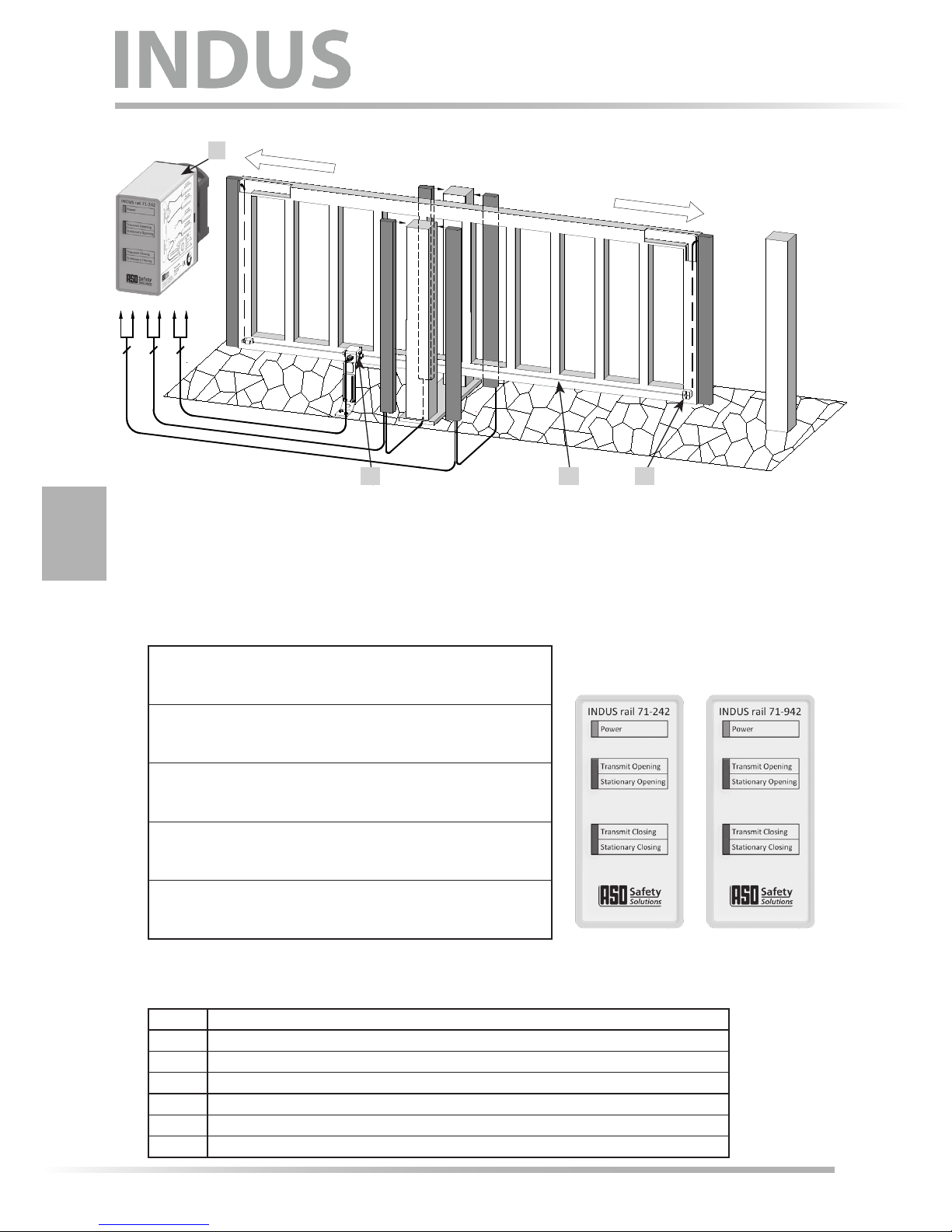
INDUS rail 71-242 + INDUS rail 71-942
Indukves Signalübertragungssystem